transmission MITSUBISHI SPYDER 1990 Service Owner's Manual
[x] Cancel search | Manufacturer: MITSUBISHI, Model Year: 1990, Model line: SPYDER, Model: MITSUBISHI SPYDER 1990Pages: 2103, PDF Size: 68.98 MB
Page 1167 of 2103
AUTOMATIC TRANSAXLE
ENGINE (NON-TURBO)>
.
to GROU’P 00
RefertoGROUP 00 Maintenance Service.
TCM RESETTING
(1) Disconnect the negative battery cable from the
before replacing the transaxle out overhaul.
(2) After work has been completed, check
trouble codes (DTC). If DTC 12 (“Battery power was
disconnected since last power has been
generated, this DTC must be cleared. Furthermore, select “Special function” on the scan tool
and then set the scan tool to Quick Learn mode (car ry
out this operation from the scan tool screen). Then input
the clutch volume index into the
PINION FACTOR WRITING PROCEDURE
REPLACEMENT OR TIRE SIZE
NOTE
With transmissions, the TCM uses the rotation speed
of the transaxle output shaft to calculate the vehicle speed
and cumulative distance
Because of this, it is
necessary to input (or update) the tire size coeffi cient into
the TCM memory after the TCM has been replaced or t he
tire size has been changed.
(1) Select “Special function” on the scan
and then set
the scan tool to Pinion Factor mode (carry out this operation from the scan tool screen). Then input (o r
update) the tire size coefficient the TCM memory.
Note that new
do not a tire size
already input.
TSB Revision
Page 1174 of 2103
AUTOMATIC TRANSAXLE
ENGINE (NON-TURBO)> On-vehicle Service
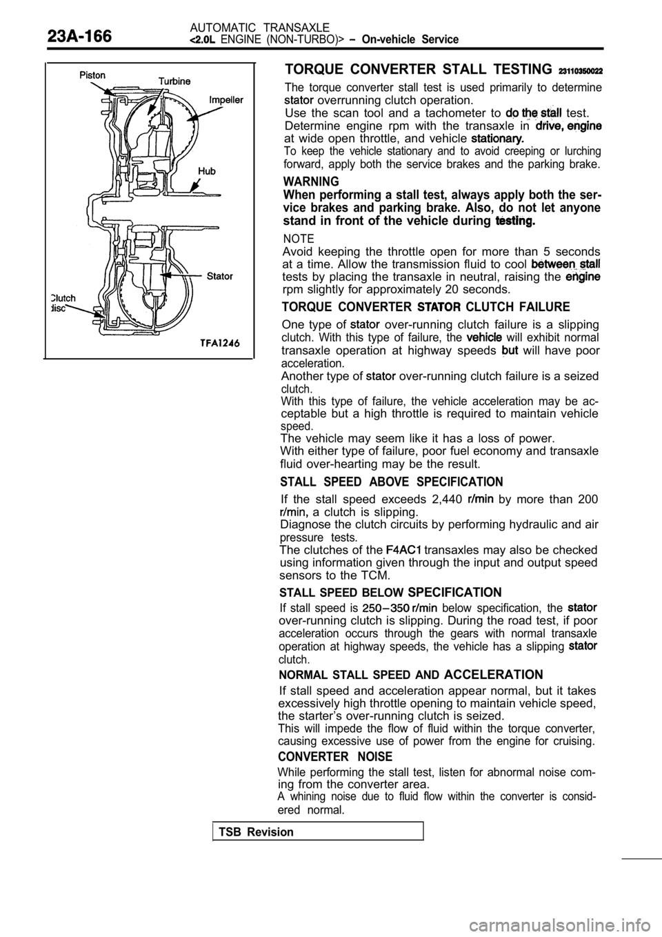
TORQUE CONVERTER STALL TESTING
The torque converter stall test is used primarily to determine
overrunning clutch operation.
Use the scan tool and a tachometer to
test.
Determine engine rpm with the transaxle in
at wide open throttle, and vehicle
To keep the vehicle stationary and to avoid creepin g or lurching
forward, apply both the service brakes and the parking brake.
WARNING
When performing a stall test, always apply both the ser-
vice brakes and parking brake. Also, do not let any one
stand in front of the vehicle during
NOTE
Avoid keeping the throttle open for more than 5 seconds
at a time. Allow the transmission fluid to cool
tests by placing the transaxle in neutral, raising the
rpm slightly for approximately 20 seconds.
TORQUE CONVERTER CLUTCH FAILURE
One type of over-running clutch failure is a slipping
clutch. With this type of failure, the will exhibit normal
transaxle operation at highway speeds will have poor
acceleration.
Another type of over-running clutch failure is a seized
clutch.
With this type of failure, the vehicle acceleration may be ac-
ceptable but a high throttle is required to maintai n vehicle
speed.
The vehicle may seem like it has a loss of power.
With either type of failure, poor fuel economy and transaxle
fluid over-hearting may be the result.
STALL SPEED ABOVE SPECIFICATION
If the stall speed exceeds 2,440 by more than 200
a clutch is slipping.
Diagnose the clutch circuits by performing hydrauli c and air
pressure tests.
The clutches of the transaxles may also be checked
using information given through the input and outpu t speed
sensors to the TCM.
STALL SPEED BELOW SPECIFICATION
If stall speed is below specification, the
over-running clutch is slipping. During the road te st, if poor
acceleration occurs through the gears with normal t ransaxle
operation at highway speeds, the vehicle has a slip ping
clutch.
NORMAL STALL SPEED AND ACCELERATION
If stall speed and acceleration appear normal, but it takes
excessively high throttle opening to maintain vehic le speed,
the starter’s over-running clutch is seized.
This will impede the flow of fluid within the torqu e converter,
causing excessive use of power from the engine for cruising.
CONVERTER NOISE
While performing the stall test, listen for abnormal noise com-
ing from the converter area.
A whining noise due to fluid flow within the conver ter is consid-
ered normal.
TSB Revision
Page 1203 of 2103
AUTOMATIC TRANSAXLE
ENGINE (NON-TURBO)>
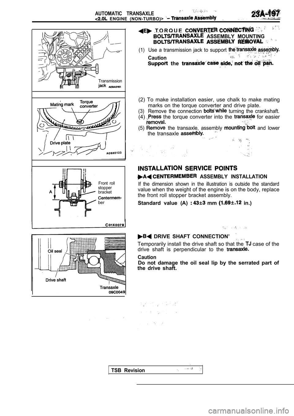
Transmission
I
Front roll
stopper bracket
ber
T O R Q U E
ASSEMBLY MOUNTING
(1)Use a transmission jack to support
Caution
the
(2) To make installation easier, use chalk to make mating
marks on the torque converter and drive plate.
(3)Remove the connection turning the crankshaft.
(4) the torque converter into the for easier
(5) the transaxle, assembly and lower
the transaxle
ASSEMBLY INSTALLATION
If the dimension shown in the illustration is outsi de the standard
value when the weight of the engine is on the body, replace
the front roll stopper bracket assembly.
Standard value (A)
mm in.)
DRIVE SHAFT CONNECTION’
Temporarily install the drive shaft so that the case of the
drive shaft is perpendicular to the
Caution
Do not damage the oil seal lip by the serrated part of
the drive shaft.
TSB Revision
Page 1208 of 2103
AUTOMATIC TRANSAXLE
OVERHAUL General Information
GENERAL INFORMATION
Precautions to be taken when disassembling and the
l
Because the automatic transaxle is composed of component parts high degree of
precision, these parts should be very carefully han dled during disassembly andassembly so as not
to scar or scratch them.
A rubber mat should be placed on the workbench, it should kept clean.
During disassembly, cloth gloves or shop towels sho uld not be used. If
items must be used,
either use articles made of nylon, or use paper tow els.
All disassembled parts must be thoroughly cleaned.
Metal parts may be cleaned with ordinary detergents , but must be thoroughly air dried.
Clean the clutch disc, resin thrust plate and rubber parts by using transmission fluid),
being very careful that dust, dirt, etc. do not adhere to them.
Do not reuse gaskets, oil seals, or rubber parts.
Replace such parts with new ones at every reassembl y. The’ O-ring of the oil level gauge need not
be replaced.
Do not use grease other than petrolatum jelly.
Apply ATF to friction components, rotating parts, a nd sliding parts before installation.
A new clutch disc should be immersed in ATF for at least two hours before installation.
Do not apply sealer or adhesive to gaskets.
When a bushing
be replaced, replace the assembly in which incorporated.
If the transaxle main unit is damaged, also disasse mble and clean the cooler system.
TSBRevision
Page 1222 of 2103
6AUTOMATIC TRANSAXLE
OVERHAUL Transaxle
70. Clamp
71.
Gasket
72. Oil pan
73.
Gasket
74.Drain plug
75.O-ring
76.Set screw77.O-ring78.Detent plate
79. Sprag rod support
80. Parking sprag rod
2170046
81.Control shaft
82. D-ring
83. Transfer shaft cover
84.Lock nut
85. Driven gear
86.Outer race
87.Spacer
-88.Outer race89.Transaxle case
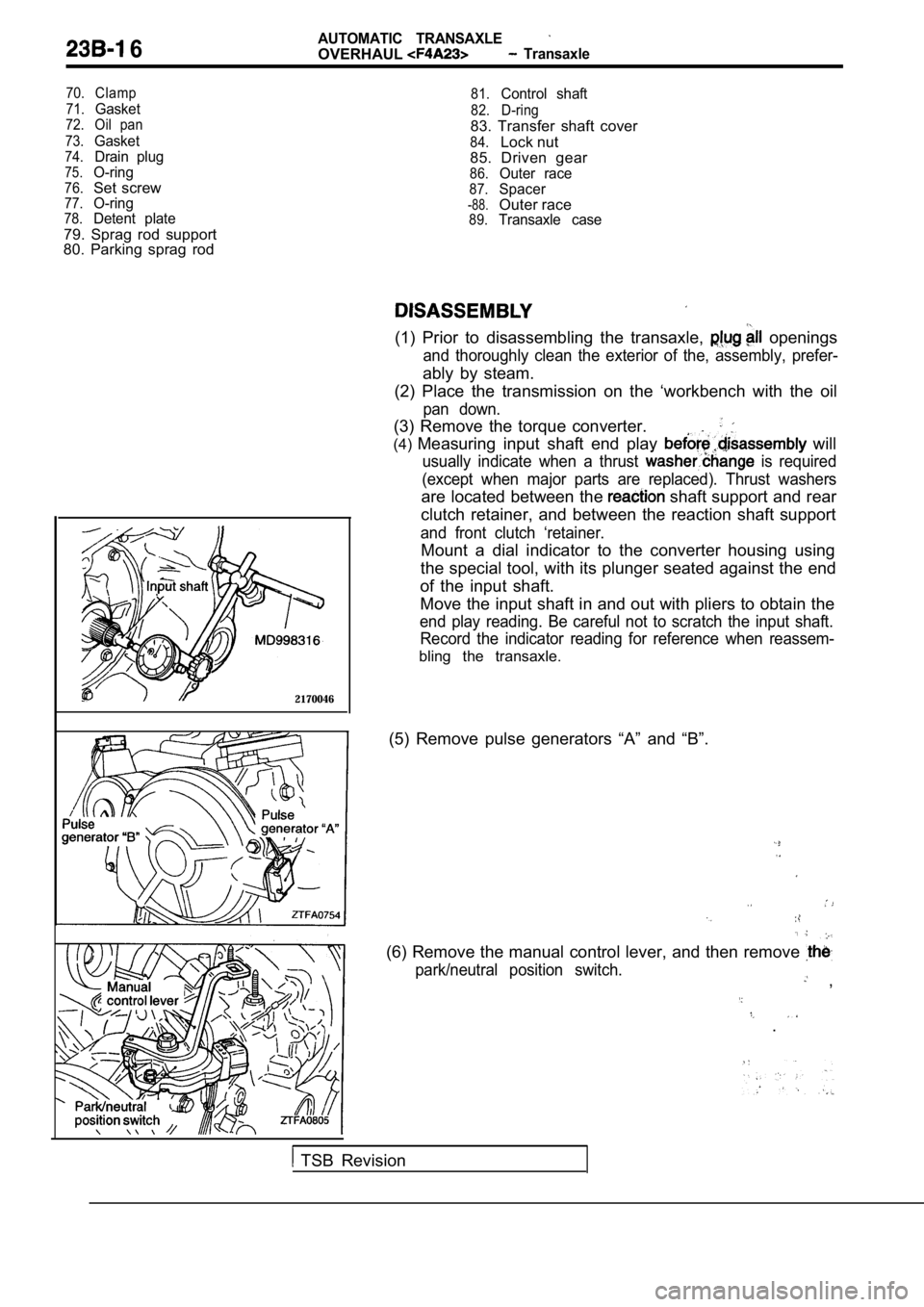
(1) Prior to disassembling the transaxle, openings
and thoroughly clean the exterior of the, assembly, prefer-
ably by steam.
(2) Place the transmission on the ‘workbench with t he oil
pan down.
(3) Remove the torque converter.
.
(4)Measuring input shaft end play will
usually indicate when a thrust is required
(except when major parts are replaced). Thrust wash ers
are located between the shaft support and rear
clutch retainer, and between the reaction shaft sup port
and front clutch ‘retainer.
Mount a dial indicator to the converter housing usi ng
the special tool, with its plunger seated against t he end
of the input shaft.
Move the input shaft in and out with pliers to obta in the
end play reading. Be careful not to scratch the inp ut shaft.
Record the indicator reading for reference when rea ssem-
bling the transaxle.
(5) Remove pulse generators “A” and “B”.
(6) Remove the manual control lever, and then remov e
park/neutral position switch. ,
.
TSB Revision
Page 1232 of 2103
A U T O M A T I C T R A N S A X L E
OVERHAUL
Oil pump side
Pressure spring
REASSEMBLY
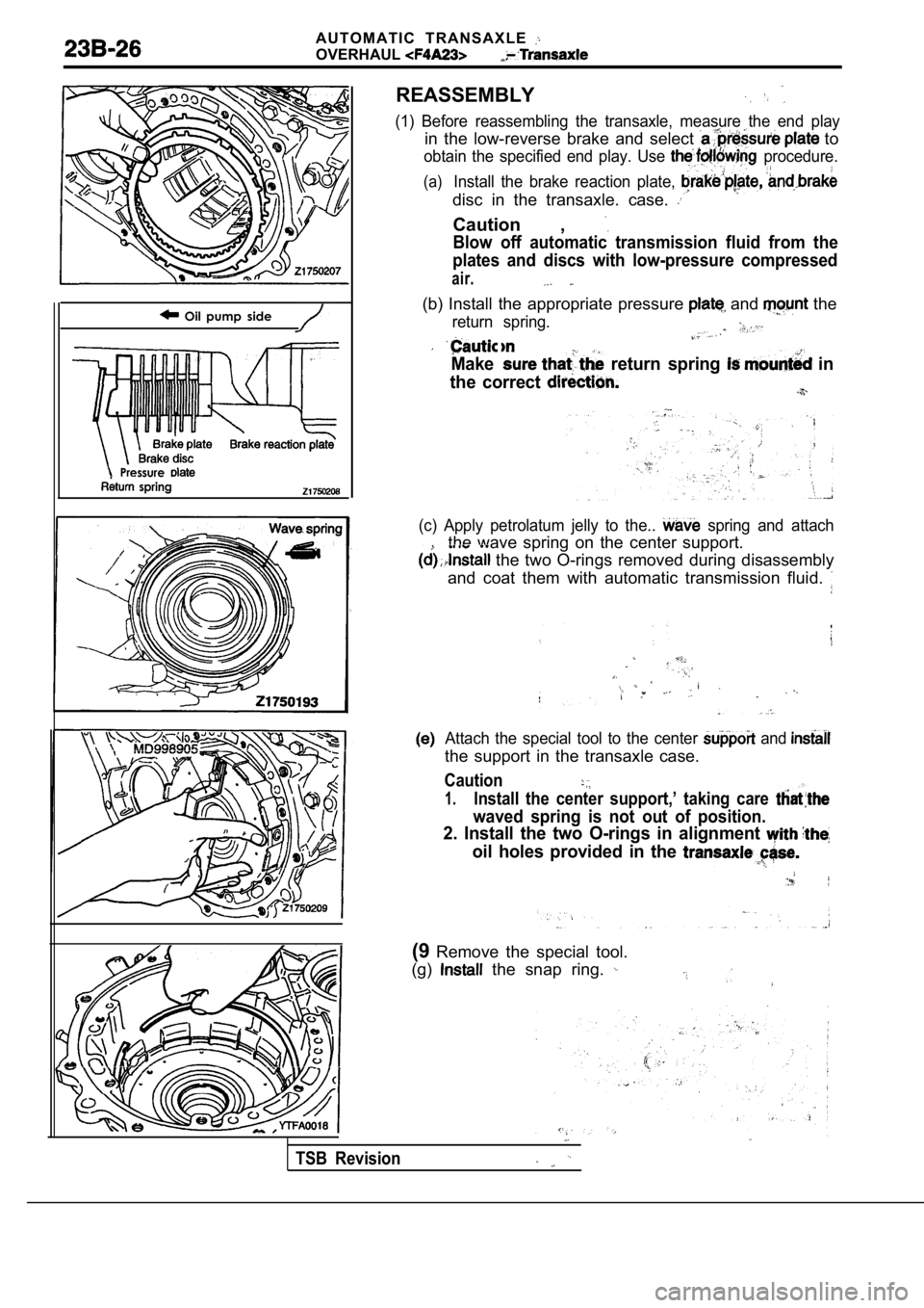
(1) Before reassembling the transaxle, measure the end play
in the low-reverse brake and select to
obtain the specified end play. Use procedure.
(a)Install the brake reaction plate,
disc in the transaxle. case.
Caution ,
Blow off automatic transmission fluid from the
plates and discs with low-pressure compressed
air.
(b) Install the appropriate pressure and the
return spring.
Make return spring in
the correct
(c) Apply petrolatum jelly to the.. spring and attach
the wave spring on the center support.
the two O-rings removed during disassembly
and coat them with automatic transmission fluid.
i .
Attach the special tool to the center and
the support in the transaxle case.
Caution
1.Install the center support,’ taking care
waved spring is not out of position.
2. Install the two O-rings in alignment
oil holes provided in the
(9 Remove the special tool.
(g)
the snap ring.
TSB Revision
Page 1241 of 2103
A U T O M A T I C T R A N S A X L E
OVERHAUL Transaxle
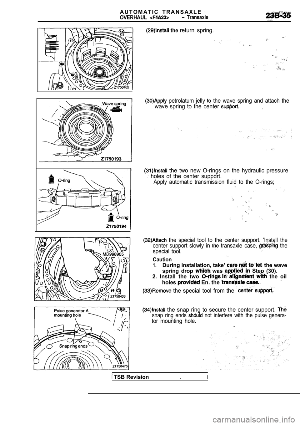
the return spring.
--
petrolatum jelly the wave spring and attach the
wave spring to the center ,
the two new O-rings on the hydraulic pressure
holes of the center suppdrt.
Apply automatic transmission fluid to the O-rings;
the special tool to the center support. ‘Install the
center support slowly in
transaxle case, the
special tool.
Caution
1.During installation, take’ the wave
spring drop
was Step (30).
2. Install the two
the oil
holes
En. the
the special tool from the
the snap ring to secure the center support.
snap ring ends not interfere with the pulse genera-
tor mounting hole.
TSB Revision.I
Page 1242 of 2103
AUTOMATIC TRANSAXLE
OVERHAUL Transaxle
D-ringO-ring
servo pistonservo
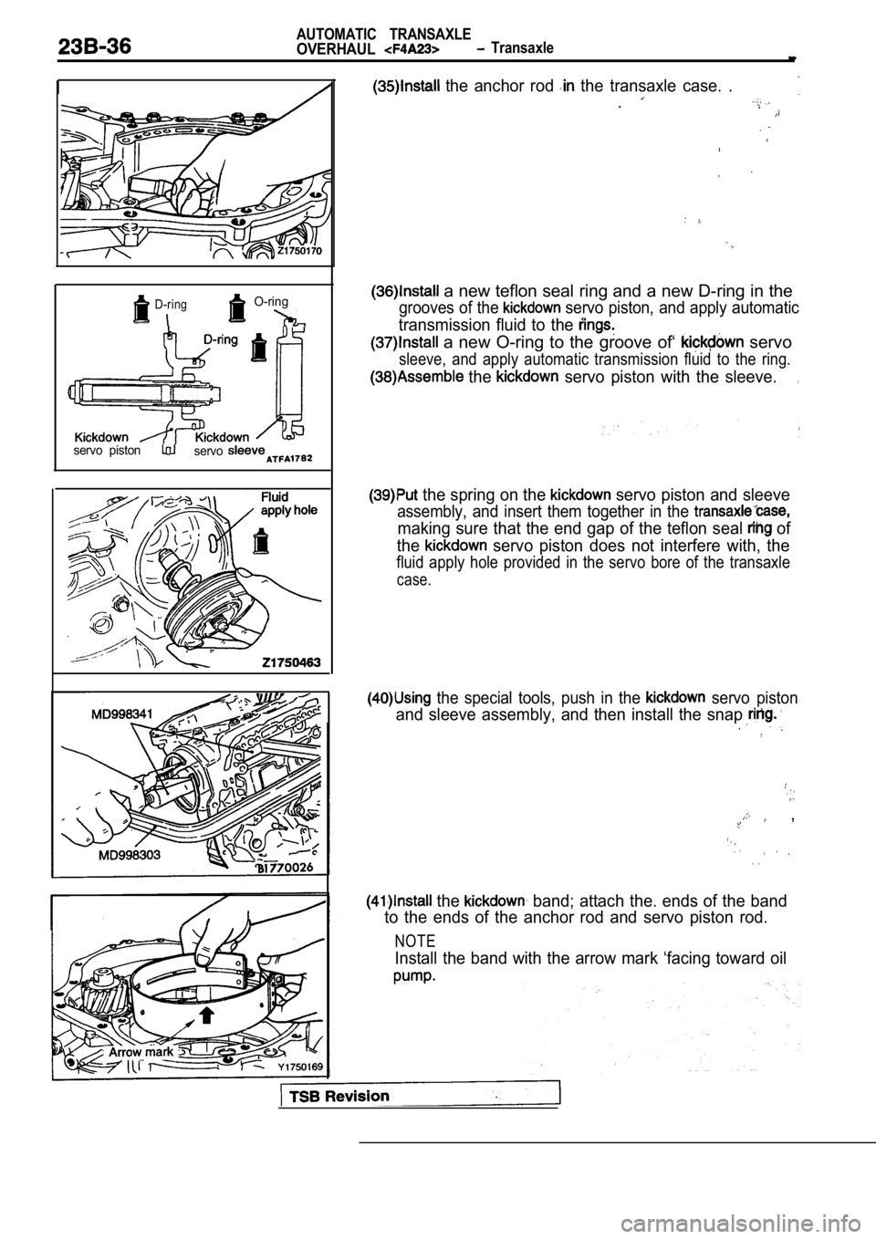
the anchor rod the transaxle case. .
.
a new teflon seal ring and a new D-ring in the
grooves of the servo piston, and apply automatic
transmission fluid to the
a new O-ring to the groove of‘ servo
sleeve, and apply automatic transmission fluid to the ring.
the servo piston with the sleeve.,
the spring on the servo piston and sleeve
assembly, and insert them together in the
making sure that the end gap of the teflon seal of
the
servo piston does not interfere with, the
fluid apply hole provided in the servo bore of the transaxle
case.
the special tools, push in the servo piston
and sleeve assembly, and then install the snap
,
,
the band; attach the. ends of the band
to the ends of the anchor rod and servo piston rod.
NOTE
Install the band with the arrow mark ‘facing toward oil
Page 1253 of 2103
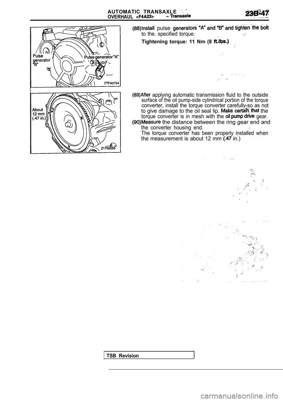
AUTOMATIC TRANSAXLE
OVERHAUL
pulse
to the. specified torque.
Tightening torque: 11 Nm (8
applying automatic transmission fluid to the outside
surface of the oil pump-side cylindrical portion of the torque
converter, install the torque converter carefully-so as not
to give damage to the oil seal lip. the
torque converter is in mesh with the gear.
the distance between the ring gear end and
the converter housing end.
The torque converter has been properly installed wh en
the measurement is about 12 mm in.)
TSB Revision
Page 1270 of 2103
AUTOMATIC TRANSAXLE
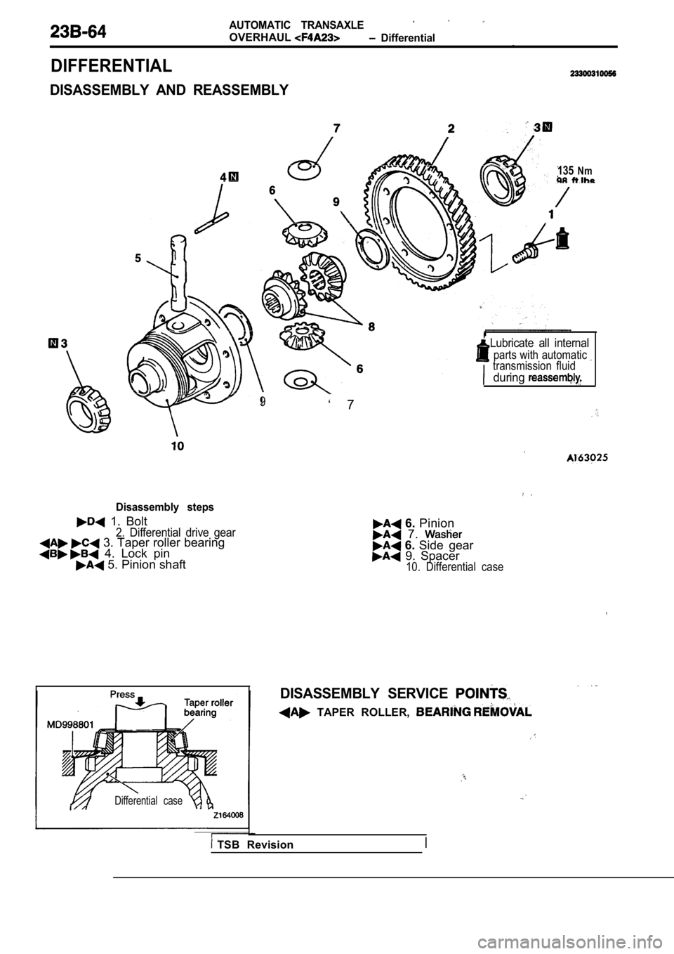
OVERHAUL Differential.
DIFFERENTIAL
DISASSEMBLY AND REASSEMBLY
135Nm
Lubricate all internal
parts with automatic transmission fluid
during
Disassembly steps
1. Bolt2. Differential drive gear 3. Taper roller bearing 4. Lock pin 5. Pinion shaft
Differential case
9‘ 7
6. Pinion 7. 6. Side gear 9. Spacer10. Differential case
DISASSEMBLY SERVICE
TAPER ROLLER,
TSB Revision