sensor NISSAN 300ZX 1984 Z31 Electrical System User Guide
[x] Cancel search | Manufacturer: NISSAN, Model Year: 1984, Model line: 300ZX, Model: NISSAN 300ZX 1984 Z31Pages: 116, PDF Size: 3.42 MB
Page 60 of 116
METER AND GAUGES -Digital Type Combination Gauge
,- Trouble-shooting (Cont'd)
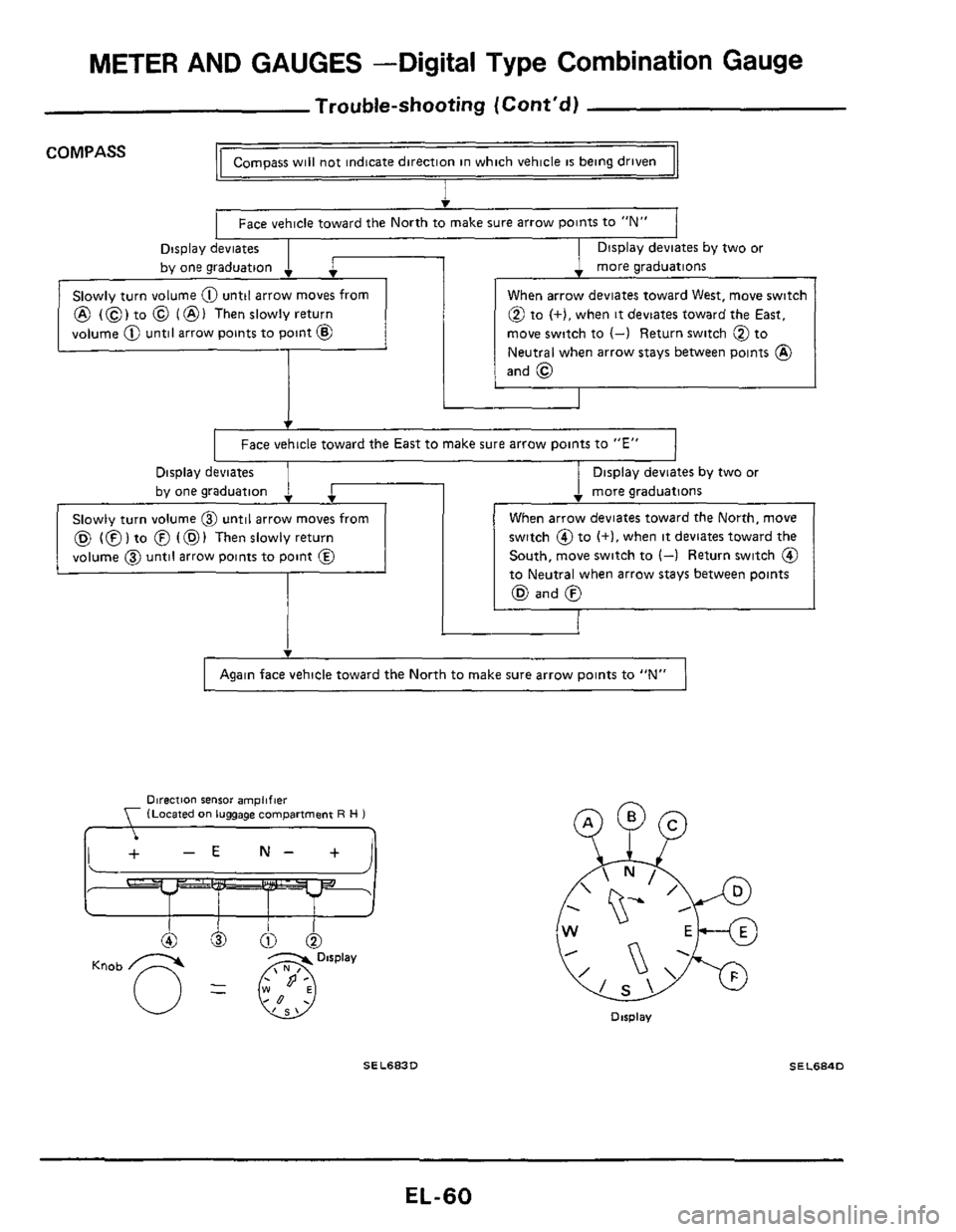
Compass will not indicate direction in which vehicle is being driven COMPASS
I
Face vehicle toward the North to make sure arrow points to "N"
Display deviates
by one graduation
. more graduations
Display deviates by two or
. 1 SIOWI~ turn volume 0 until arrow moves from
@ (0) to @ (@I Thenslowlyreturn
volume
@ until arrow points to point @
When arrow deviates toward West, move switch
@ to (+),when it deviates toward the East,
move switch to
(-) Return switch @ to
Neutral when arrow stays between points
@)
and @
I Face vehicle toward the East to make sure arrow points to "E" 1
Display deviates
SIOWIV turn volume @ until arrow moves from
(Q (0) to @ (@I Then slowly return
volume
@ until arrow points to point @
1 Display deviates by two or
. more graduations
switch @to (+I, when it deviates toward the
South, move switch
to (4 Return switch @
to Neutral when arrow stays between points
(Q and 0
I Again face vehicle toward the North to make sure arrow points to "N" 1
Direction sensor amplifier (Located on luggage compartment R H 1 , ,
Dirplav
SEL683D SEL684D
EL-60
Page 61 of 116
METER AND GAUGES -Digital Type Combination Gauge
Trouble-shooting (Cont'd)
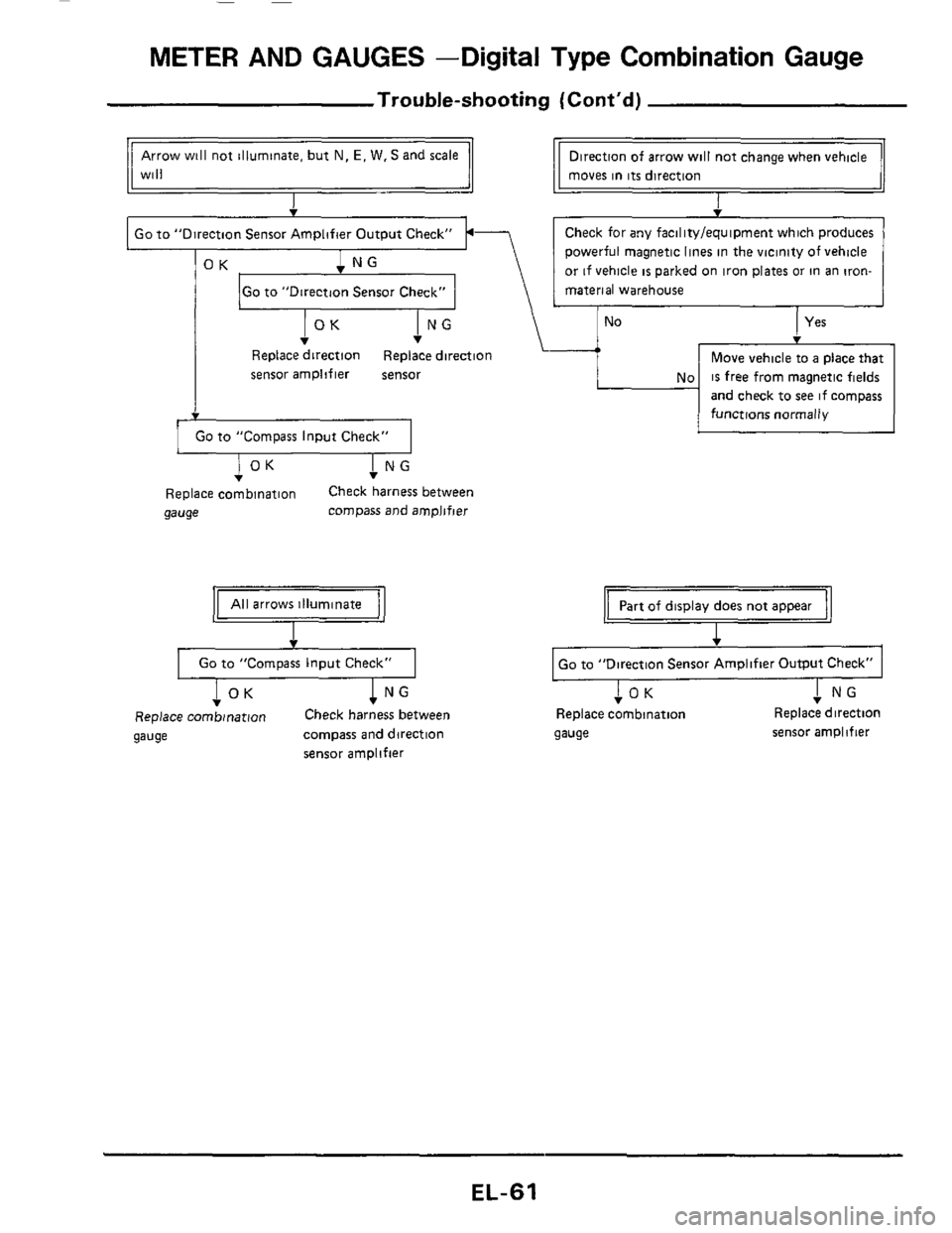
Go to "Direction Sensor Check"
Arrow will not illuminate, but N, E, W. S and scale
Will
No
Direction of arrow will not change when vehicle
moves in
its direction
I
Yes
I Go to "Direction Sensor Amplifier Output Check" I.-
No
Move vehicle to a place that
is free from magnetic fields
and check to
see if compass
functions normally
I NG v
Replace direction Replace direction
sensor amplifier sensor
1 GO to "Compass Input Check" I
I NG T I OK T
Replace combination Check harness between
gauge compass and amplifier
All arrows illuminate
v
Go to "Compass Input Check"
T I OK ! NG
Replace combination Check harness between
gauge compass and direction
sensor amplifier
Part of display does not appear
I
Go to "Direction Sensor Amplifier Output Check"
I NG !OK T Replace combination Replace direction
gauge sensor amplifier
EL-61
Page 62 of 116
METER AND GAUGES -Digital Type Combination Gauge
Trouble-shooting (Cont'd)
v
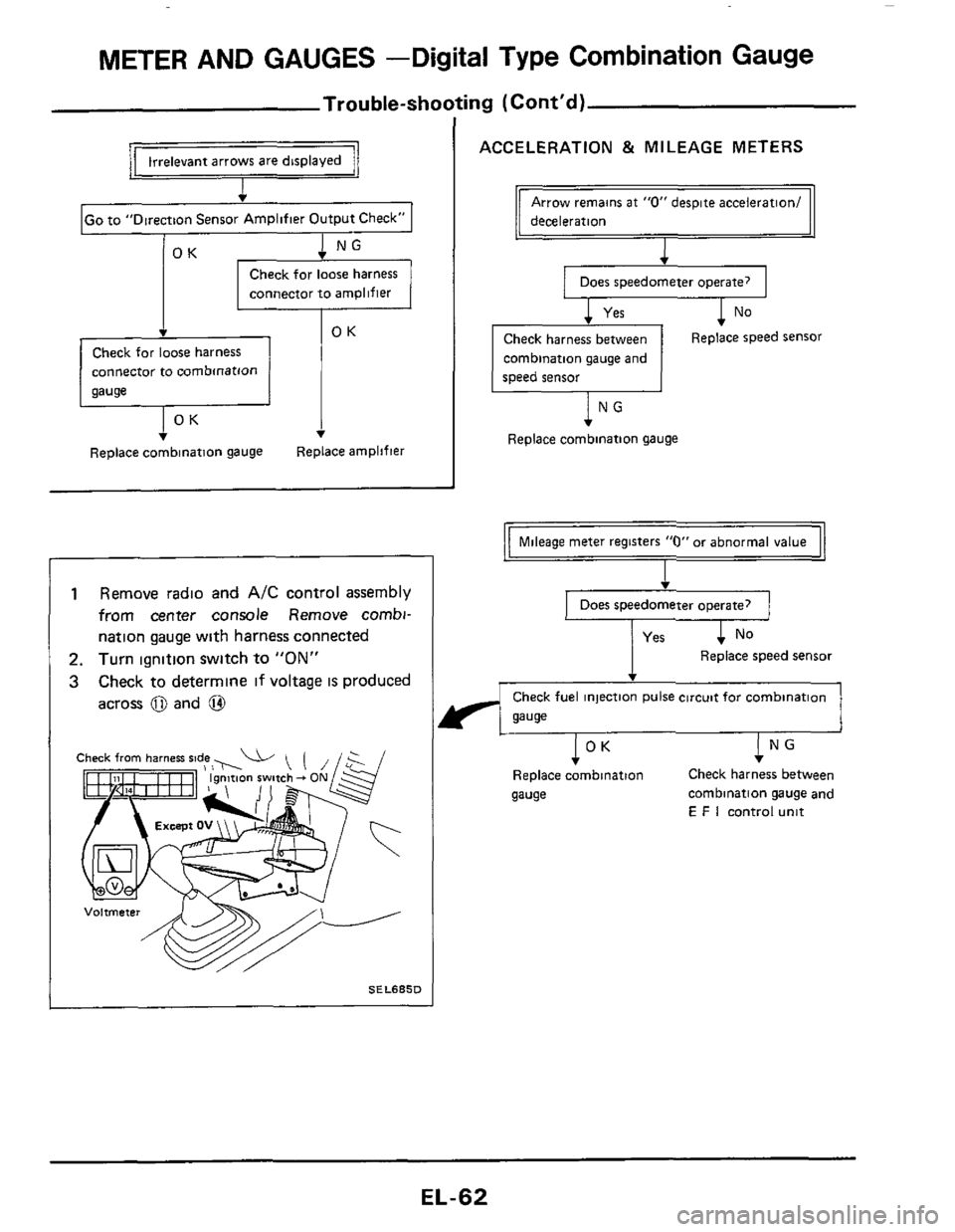
IGo to "Direction Sensor Amplifier Output Check" I
1 NG v
Check for loose harness
connector to
amplifier
Check for loose harness
connector to combmatlon
Replace combinatlon gauge Replace amplifier
I
1 Remove radio and AIC control assembly
from center console Remove combi-
nation gauge with harness connected
2. Turn ignition switch to "ON"
3 Check to determine if voltage IS produced
across
0 and @
SELSBSD
ACCELERATION & MILEAGE METERS
deceleration
Does speedometer operate?
1 No
Check harness between
combination gauge and
speed sensor Replace speed sensor
lNG
Replace combination gauge
Mileage meter registers "0" or abnormal value
I
Does speedometer operate?
Replace speed sensor
Check fuel injection pulse circuit for combination
gauge
I NG v
Check harness between
Replace combination
gauge combination gauge and
E F I control unit
IOK
EL-62
Page 63 of 116
METER AND GAUGES -Digital Type Combination Gauge
@@6
100
100
100
100
010
010
010
010
001
001
001
001
000
000
000
000
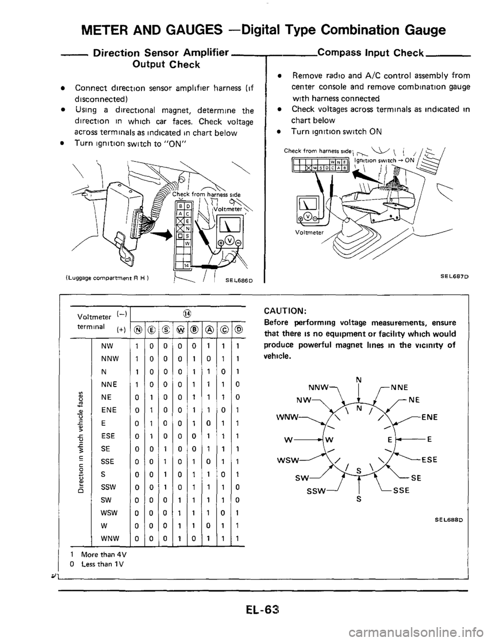
- Direction Sensor Amplifier -
Output Check
Connect direction sensor amplifier harness (if
disconnected)
Using a directional magnet, determine the
direction in which car faces. Check voltage
across terminals
as indicated in chart below
Turn ignition switch to
"ON"
- Compass input Check
Remove radio and A/C control assembly from
center console and remove combination gauge
with harness connected
Check voltages across terminals
as indicated in
chart below
Turn ignition switch ON
Ch
SEL6870
Voltmeter (-1
terminal (+)
NW
NNW
N
NNE
NE
ENE
E
ESE
SE
SSE
S
ssw
sw
wsw
W
WNW
1 Morethan4V
0 Lessthan 1V
I -
@ -
0
0
0
0
0
0
0
0
0
0
0
0
1
1
1
1 -
-
8 -
0
1
1
1
1
1
1
0
0
1
1
1
1
1
1
0 -
-
@ -
1
0
1
1
1
1
0
1
1
0
1
1
1
1
0
1 -
-
-
1
1
0
1
1
0
1
1
1
1
0
1
1
0
1
1
-
-
0 -
1
1
1
0
0
1
1
1
1
1
1
0
0
1
1
1 -
CAUTION:
Before performing voltage measurements, ensure
that there IS no equipment or facility which would
produce powerful magnet lines
in the vicinity of
vehicle.
N
NNW? I rNNE
WNW ENE
. ,
w4w Ek-E
SEL688D
EL-63
Page 64 of 116
METER AND GAUGES -Digital Type Combination Gauge
@ Io
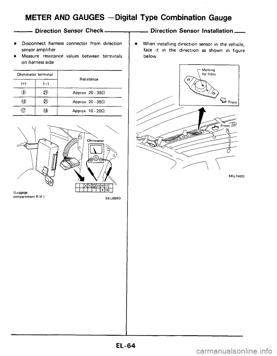
Direction Sensor Check
Disconnect harness connector from direction
Measure resistance values between terminals
sensor amplifier
on harness side
Approx 20.35.Q
Resistance
0
alol Approx 20.35.Q ~
Approx 1O.ZO.Q
SEL689D compartment R H )
- Direction
Sensor Installation -
When installing direction sensor in the vehicle,
face
it in the direction as shown in figure
below
r Markins
SELJ4ZD
EL-64
Page 67 of 116
METER AND GAUGES -Needle Type Combination Meter
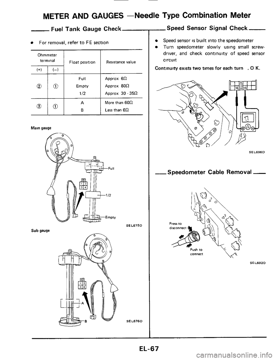
Ohmmeter
terminal
,+) , ~-, 1 Float position
Fuel Tank Gauge Check
For removal, refer to FE section
Resistance value
Full
00 EmpN
112
Approx 652
Approx 8052
Approx 30 - 3552
More than 6052
Less than 652
Main gauge
Sub gauge
SEL6750
SEL67SD
,-Speed Sensor Signal Check
Speed sensor is built into the speedometer
Turn speedometer slowly using small screw-
driver, and check continuity of speed sensor
circuit
Continuity exists two times for each turn . 0 K.
SEL696D
--Speedometer Cable Removal -
Press to
L? connect
SEL692D
EL-67
Page 68 of 116
METER AND GAUGES -Needle Type Combination Gauge
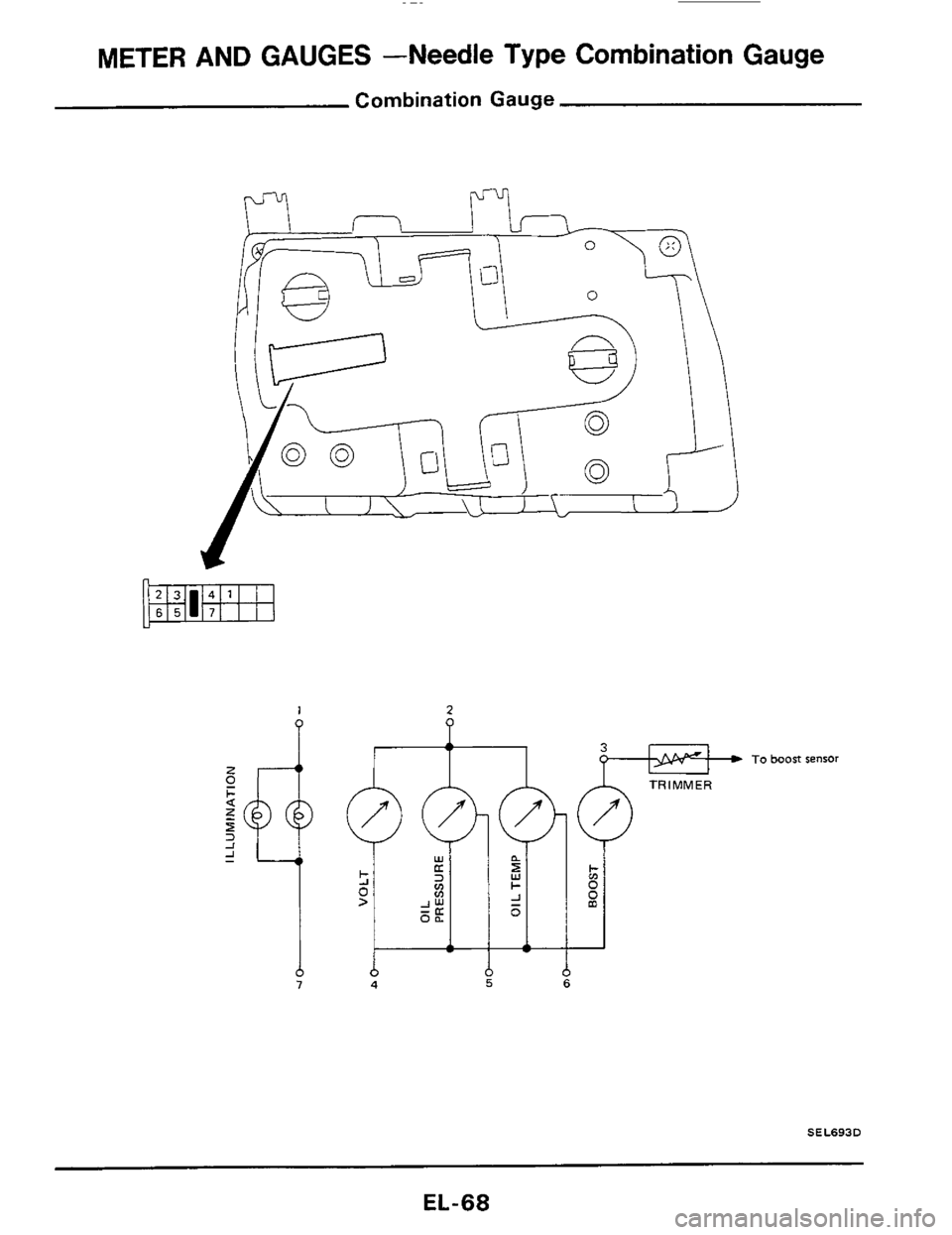
Combination Gauge
I
2
P I To boost sensor
z c
+ 0 i m 0
Y
-
b 4
SEL693D
EL-68
Page 69 of 116
01 L OIL OIL
PRESSURE TEMPERATURE PRESSURE SENSOR SENSOR SENSOR
I
BOOST
SENSOR
v) m r
P 0
%
@ f$& BODY GROUND
m
h
(Instrument harness)
FUSE
BLOCK J
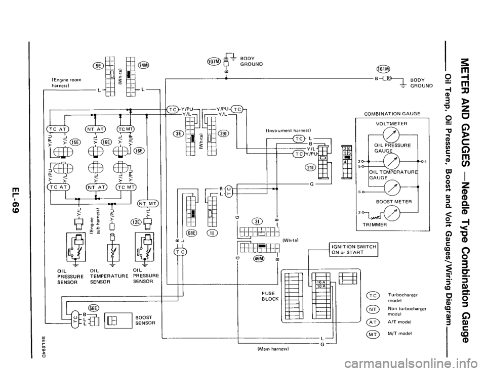
COMBINATION GAUGE
VOLTMETER
GAUGE
4
GAUGE
BOOST METER
TRIMMER
IGNITION SWITCH
ON or START
I G (Main harness)
Turbocharger
model
Nom turbocharger
model
A/T model
M/T model
3
m
-I
m
rn
D
z
U
0
D
C
0
rn
ui
I
z
(D (D Q
T
-I Y
0 (D
0 0
3
0
¶ 9)
9) c
0
(D
-.
E
G)
Page 70 of 116
METER AND GAUGES -Needle Type Combination Gauge
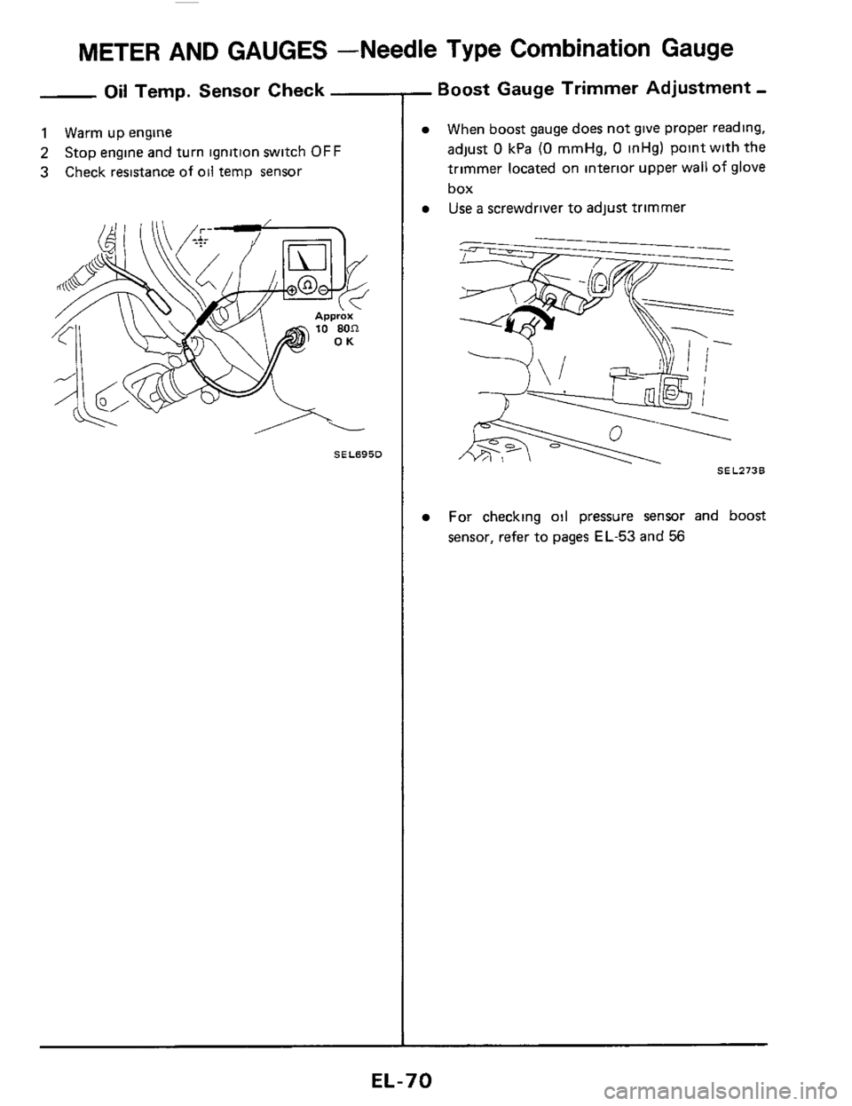
Oil Temp. Sensor Check
1 Warm up engine
2
3
Stop engine and turn ignition switch OFF
Check resistance of
oil temp sensor
SEL695D
- Boost Gauge Trimmer Adjustment -
When boost gauge does not give proper reading,
adjust
0 kPa (0 mmHg, 0 inHg) point with the
trimmer located on interlor upper wall of glove
box
Use a screwdriver to adjust trimmer
For checking oil pressure sensor and boost
sensor, refer to pages EL-53 and 56
EL-70
Page 75 of 116
WARNING LAMPS AND CHIME
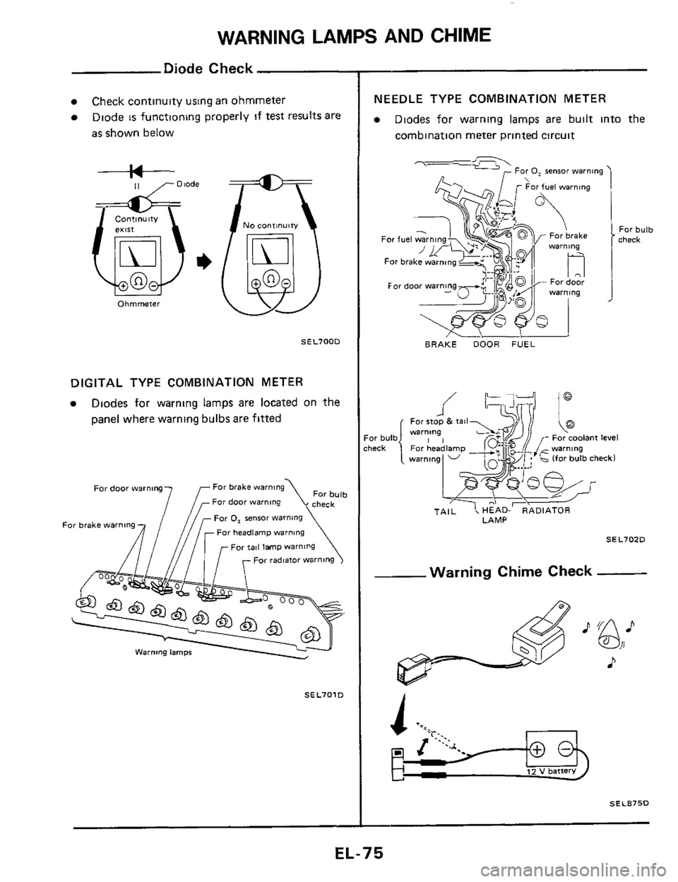
Diode Check
Check continuity using an ohmmeter
Diode
is functioning properly if test results are
as shown below
--I+-- 11 ,- Diode
Ohmmeter
NO continuity
@
SEL700D
DIGITAL TYPE COMBINATION METER
Diodes for warning lamps are located on the
panel where warning bulbsare fitted
For bulb check
For brake warning
7f For door warning
Far door warning
For tail lamp warning
For radmtor warning
Far 0, sensor warning
Far headlamp warning For brake warning
SEL701D
-~
NEEDLE TYPE COMBINATION METER
Diodes for warning lamps are built into the
Combination meter printed circuit
7- For 0, sensor warning
BRAKE DOOR FUEL
For bulb check
LAMP
SEL70ZD
--Warning Chime Check
A
SEL875D
EL-75