NISSAN 300ZX 1984 Z31 Front Suspension User Guide
Manufacturer: NISSAN, Model Year: 1984, Model line: 300ZX, Model: NISSAN 300ZX 1984 Z31Pages: 24, PDF Size: 0.68 MB
Page 11 of 24
TENSION ROD AND STABILIZER BAR
Removal and Installation
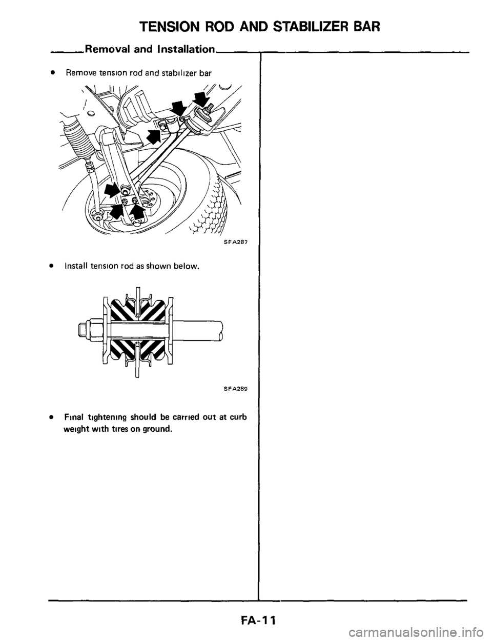
Remove tension rod and stabilizer bar
SFA287
Install tension rod as shown below.
SFA289
Final tightening should be carried out at curb
weight with tires on ground.
FA-I 1
Page 12 of 24
TRANSVERSE LINK AND LOWER BALL JOINT
Removal ar
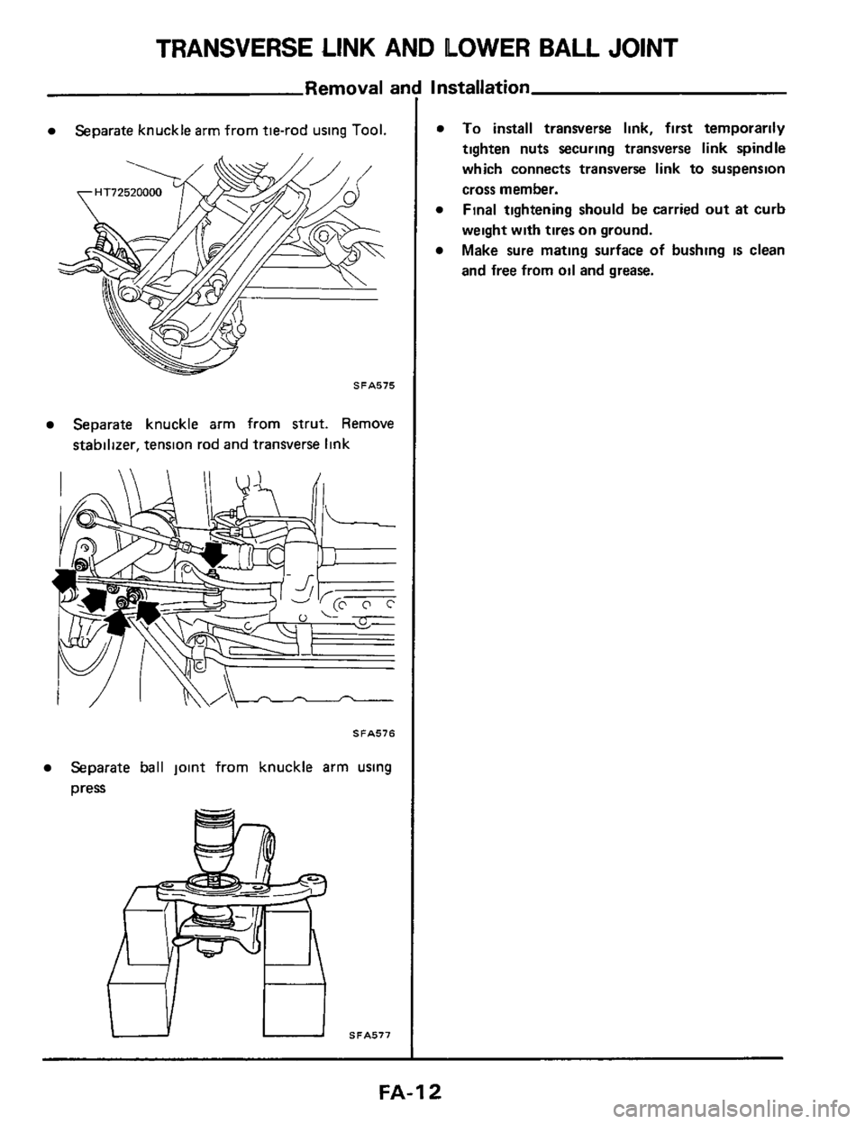
Separate knuckle arm from tie-rod using Tool.
SFA575
Separate knuckle arm from strut. Remove
stabilizer, tension rod and transverse link
SFA576
Separate ball joint from knuckle arm using
press
SFA577
Installation
To install transverse link, first temporarily
tighten nuts securing transverse
link spindle
which connects transverse
link to suspension
cross member.
Final tightening should be carried out at curb
weight with tires
on ground.
Make sure mating surface of bushing
is clean
and free from oil and grease.
FA-I 2
Page 13 of 24
TRANSVERSE LINK AND LOWER BALL JOINT
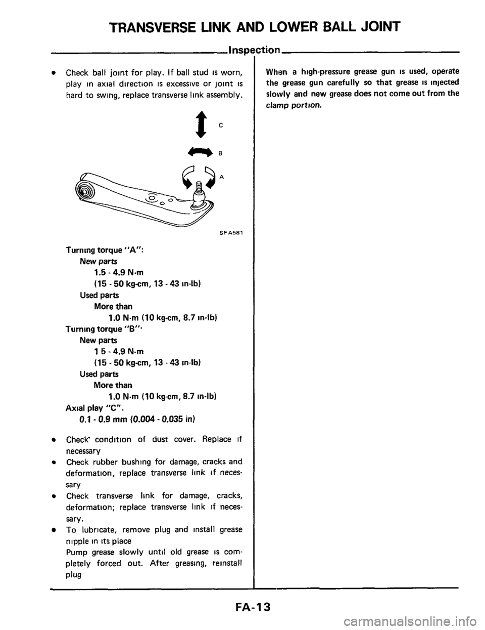
0 Check ball joint for play. If ball stud IS worn,
play in axial direction
is excessive or joint is
hard to swing, replace transverse link assembly.
e 2.
Turning torque "A:
1.5.4.9 Nm
(15
- 50 kgcm, 13 - 43 in-lb)
More
than
New parts
Used parts
1.0 Nm (10 kgcm. 8.7 in-11~.
Turning torque "B".
1 5 - 4.9 N.m
(15
~ 50 kgcm, 13 - 43 in-lb)
More
than
New parts
Used parts
1.0 N.m (10 kgcm, 8.7 in-lb)
Axial play "C".
0.1 - 0.9 mm (0.004 - 0.035 in)
0 Check condition of dust cover. Replace if
necessary
0 Check rubber bushing for damage, cracks and
deformation, replace transverse link If neces-
sary
0 Check transverse link for damage, cracks,
deformation; replace transverse link if neces-
sary.
To lubricate, remove plug and install grease
nipple in
its place
Pump
grease slowly until old grease is com-
pletely forced out. After greasing, reinstall
Plug
:tion
When a high-pressure grease gun IS used, operate
the grease gun carefully so that grease IS injected
slowly and new grease
does not come out from the
clamp portion.
FA-I 3
Page 14 of 24
SUSPENSION CROSSMEMBER
Removal and Installation
Precaution
Support engine weight to remove
load from engine
mounting.
Inspection
Check suspension crossmember for deformation or
cracking. Replace
if necessary.
FA-I 4
Page 15 of 24
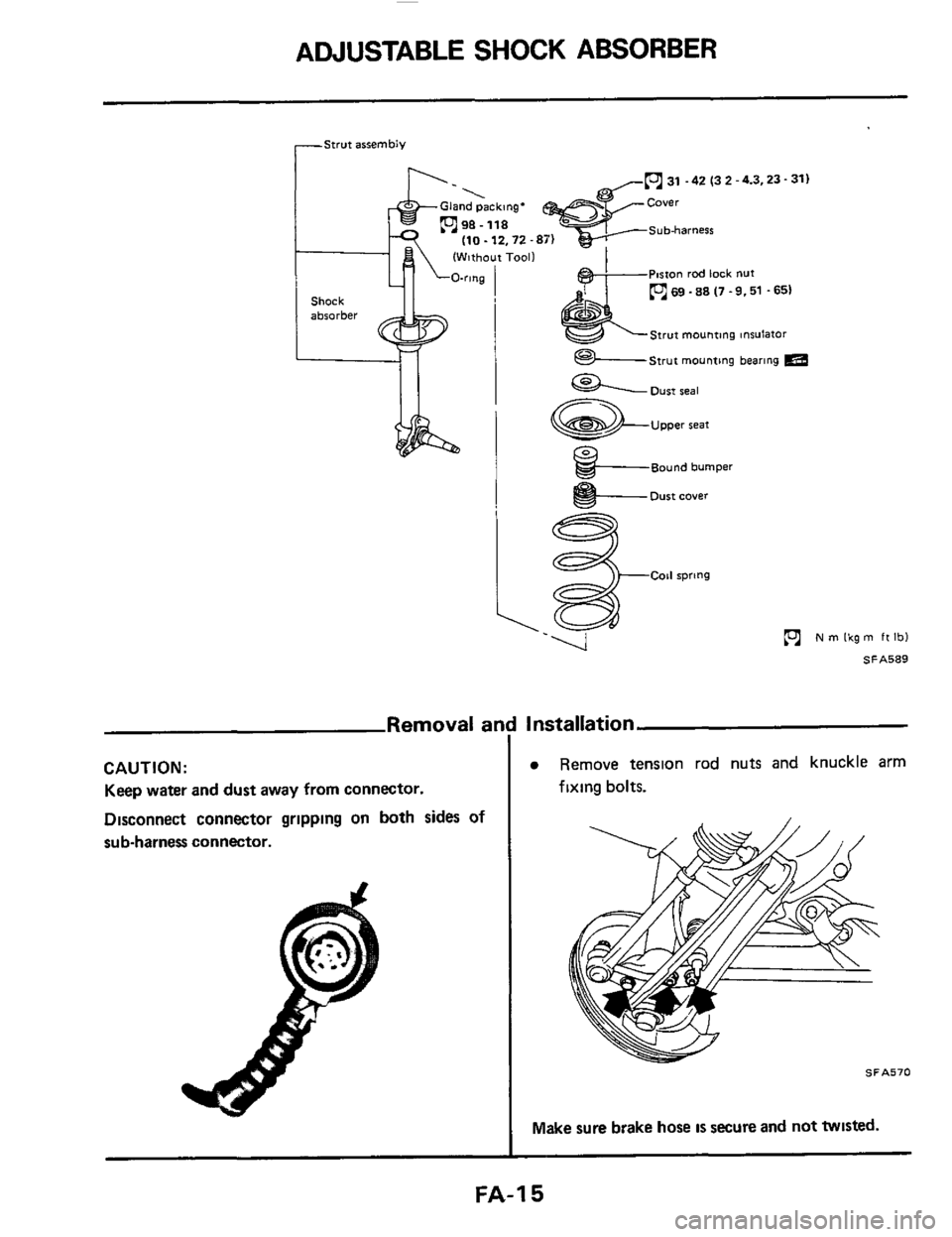
ADJUSTABLE SHOCK ABSORBER
rStwt assembly
31 -42 (3 2 -4.3,23- 31)
(Without Tool1
P~rton rod lock nut
69 .88 (7 .9.51 .651
Strut mounting tnsulator
Strut mounting bearing m
31 -42 (3 2 -4.3.23- 31)
Strut mounting tnsulator
im
Shock
absorber
Oust seal
Upper seat
Bound bumper
I e- Dust cover
ie
N m Ikg m ft Ibl
SA589
Removal ar
CAUTION:
Keep water and dust away from connector.
Disconnect connector grlpplng
on both sides of
sub-harness connector.
Installation
Remove tenslon rod nuts and knuckle arm
fixing bolts.
SFA570
Make sure brake hose IS secure and not twisted.
FA-I 5
Page 16 of 24
ADJUSTABLE SHOCK ABSORBER
-Removal and Installation (Cont'dL
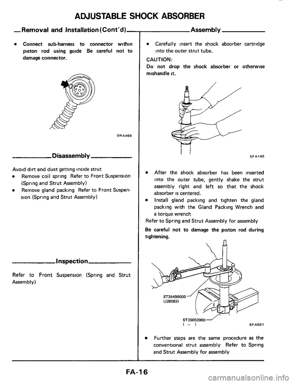
0 Connect sub-harness to connector within
piston rod using guide
Be careful not to
damage connector.
SRA469
Disassembly
Avoid dirt and dust getting inside strut
0 Remove coil spring Refer to Front Suspension
0 Remove gland packing Refer to Front Suspen-
(Spring and Strut Assembly)
sion (Spring and Strut Assembly)
Inspection
Refer to Front Suspension (Spring and Strut
Assembly)
0 Carefully insert the shock absorber cartridge
into the outer strut tube.
CAUTION:
Do not drop the shock absorber or otherwise
mishandle
it.
SFA165
After the shock absorber has been inserted
into the outer tube, gently shake the strut
assembly right and left
so that the shock
absorber
is centered.
Install gland packing and tighten the gland
packing with the Gland Packing Wrench and
a torque wrench
Refer to Spring and Strut Assembly for assembly
Be careful not to damage the piston rod during
tightening.
ST35652000- I-) SFA591
Further steps are the same procedure as the
conventional strut assembly Refer to Spring
and Strut Assembly for assembly
FA-I 6
Page 17 of 24
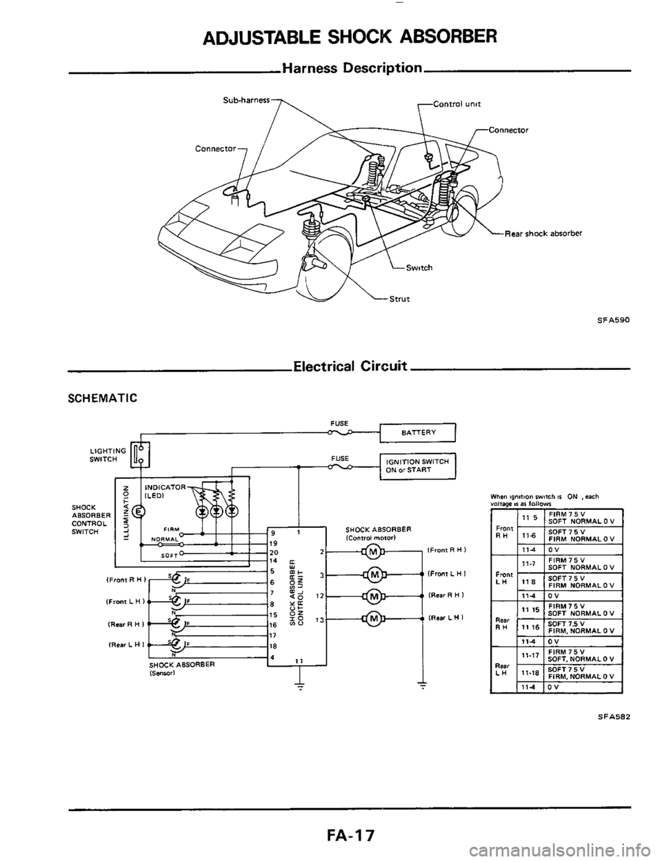
ADJUSTABLE SHOCK ABSORBER
Harness Description
Sub-harness
Rear shock absorber
SFA590
Electrical Circuit
SCHEMATIC
I I l,* I"" I
SOFT NORMAL 0 V
SOFT 7 5 V FIRM NORMAL 0 V
I 111-4 IOV I
SFAS82
FA-I 7
Page 18 of 24
I I
FA-I 8
Page 19 of 24
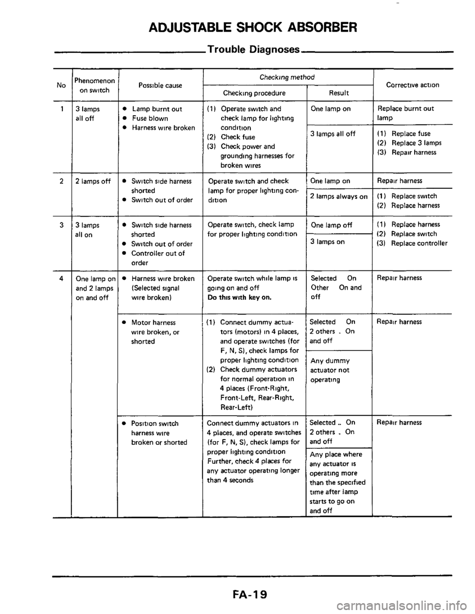
ADJUSTABLE SHOCK ABSORBER
Trouble Diagnoses
Possible cause
D Lamp burnt out
B Fuse blown
B Harness wire broken
Checking procedure
(1 I Operate switch and
check lamp for lighting
condition
(2) Check fuse
(31 Check power and
grounding harnesses for
broken wires ~~~~~~
Switch
side harness
shorted
Switch out of order
D Switch side harness
B Switch out of order
B Controller out of
shorted
order
Operate switch and check
lamp for proper lighting con-
dition
Operate switch, check lamp
for proper lighting condition
D Harness wire broken
(Selected signal
wire broken)
Operate switch while lamp is
going on and off
Do this with key on.
Corrective action
I Checking method 'henomenoi
on switch
3 lamps
all off
2 lamps off
Result
One lamp on
Replace burnt out
lamp
3 lamps all off (1) Replace fuse
(2) Replace 3 lamps
(3) Repair harness ~~
Repair
harness One lamp on
2 lamps always on (1) Replace switch
(2) Replace harness
(1 I Replace harness
(2) Replace switch
(31 Replace controller
3 lamps
311 on
One lamp off
3 lamps on
One lamp 01
and 2 lamps
on and
off
Selected On
Other On and
Off Repair harness
B Motor harness
wire broken, or
shorted
(1) Connect dummy actua-
tors (motors) in 4 places,
and operate switches (for
F, N, S),check lampsfor
proper lighting condition
(2) Check dummy actuators
for normal operation in
4 places (Front-Right,
Front-Left, Rear-Right,
Rear-Left)
Selected On
2otherr
. On
and off
Repair harness
Any dummy
actuator not
operating ~ ~~
Connect
dummy actuators in
4 places, and operate switches
(for F,
N. S), check lamps for
proper lighting condition
Further, check
4 places for
any actuator operating longer
than
4 seconds
Selected ._ On
2 others . On
and off
Repair harness D Position switch
harness wire
broken or shorted
Any place where
any actuator
is
Dperating more
than the specified
time after lamp
starts to go on
and off
FA-I 9
Page 20 of 24
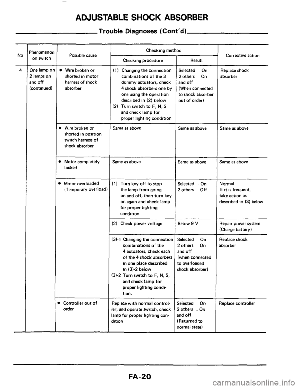
ADJUSTABLE SHOCK ABSORBER
Trouble Diagnoses (Cont'd)
'henomenoi on switch
One lamp o
2 lamps on
rnd off
[continued)
Possible cause ~
Wire
broken or
shorted in motor
harness of shock
absorber
b Wire broken or
shorted in position
switch harness of
shock absorber
1 Motor completely
locked
1 Motor overloaded
(Temporary overload
Controller out of
order
Checking method
Checking procedure
(1 I Changing the connection
combinations
of the 3
dummy actuators, check
4 shock absorbers one by
one using the operation
described
in (2) below
(2) Turn switch to F, N, S
and check lamp for
proper lighting condition
Same as above
Same as above
(1) Turn key off to stop
the lamp from going
on
and off, then turn key
on again and check lamp
for proper lighting
condition
12) Check power voltage
:3)-1 Changing the connectior
combinations of the
4 actuators, check each
of the
4 shock absorbers
in one place described
in 131-2 below
13j-2 Turn switch to F, N, S,
and check lamp for
proper lighting condi-
tion.
Replace with normal control-
er, and operate switch, check
amp for proper lighting con-
jition
Result
Selected On
2others On
and
off
(When connected
to shock absorber
out of order)
Same as above
Same as above
Selected . On
2others
Off
Below 9 V
Selected On
2others On
and off
(when connected
to overloaded
shock absorber1
jelected On
Zothers
. On
3nd off
I Returned to
iormal state)
Corrective action
Replace shock
absorber
Same as above
Same as above
Normal
If it is frequent,
take action as
described in (3) below
Repair power system
(Charge battery)
Replace shock
absorber
Replace controller
FA-20