lock NISSAN 300ZX 1984 Z31 Front Suspension Workshop Manual
[x] Cancel search | Manufacturer: NISSAN, Model Year: 1984, Model line: 300ZX, Model: NISSAN 300ZX 1984 Z31Pages: 24, PDF Size: 0.68 MB
Page 3 of 24
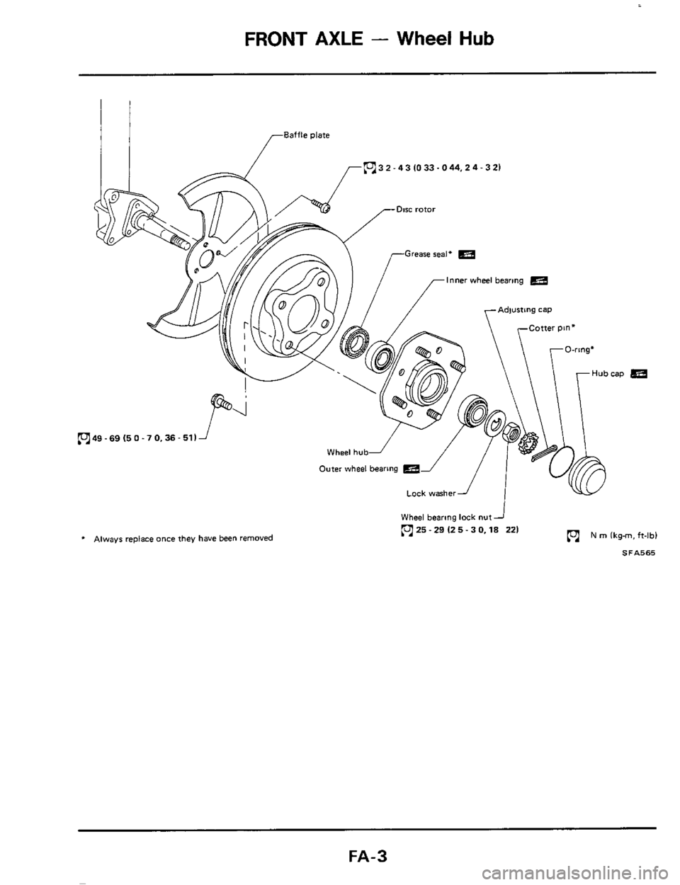
FRONT AXLE - Wheel Hub
Baffle plate
pj3 2 - 4 3 10 33.0 44,2 4 - 3 21
f
-Disc rotor
Inner wheel bearing
yAdwstlng cap
* Always replace once they have been removed N rn (kgm, ft-lb)
J
Lock washeri
Wheel bearing lock nut
25-29 125- 3 0,lS 221
SFA565
FA-3
Page 5 of 24
FRONT AXLE - Wheel Hub
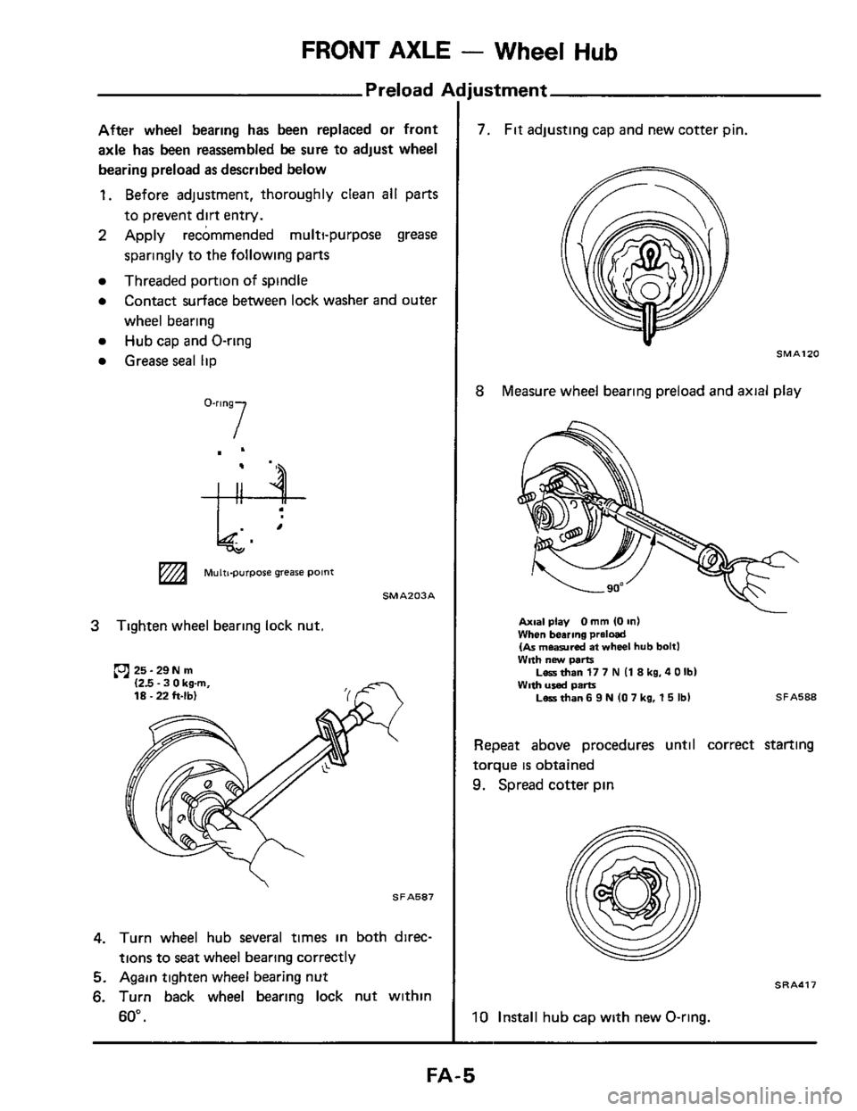
Preload Adjustment
I
After wheel bearing has been replaced or front
axle
has been reassembled be sure to adjust wheel
bearing preload
as described below
1. Before adjustment, thoroughly clean all parts
to prevent
dirt entry.
2 Apply recommended multi-purpose grease
sparingly to the following parts
Threaded portion of spindle
Contact surface between lock washer and outer
wheel bearing
Hub cap and O-ring
Grease seal lip
O-'lng7
e- "
MulttpUrpOse grease point
SMAZO3A
3 Tighten wheel bearing lock nut,
25- 29N m 12.5 - 3 0 kgm, 18.22 h-lbl
SFAS87
4. Turn wheel hub several times in both direc-
tions to seat wheel bearing correctly
5. Again tighten wheel bearing nut
6. Turn back wheel bearing lock nut within
60".
7. Fit adjusting cap and new cotter pin,
SMAlZO
8 Measure wheel bearing preload and axial play
Axial play 0 mm IO In) When bearing preloal (As meamred at wheel hub bolt1 WRh new parts
With used parts ~errthanv7~ (iakg,aoIbl
Lerrthan6 9N (07 kg. 15 Ibl SFAS88
Repeat above procedures until correct starting
torque
is obtained
9. Spread cotter pin
SRA417
10 Install hub cap with new O-ring.
I
FA- 5
Page 6 of 24
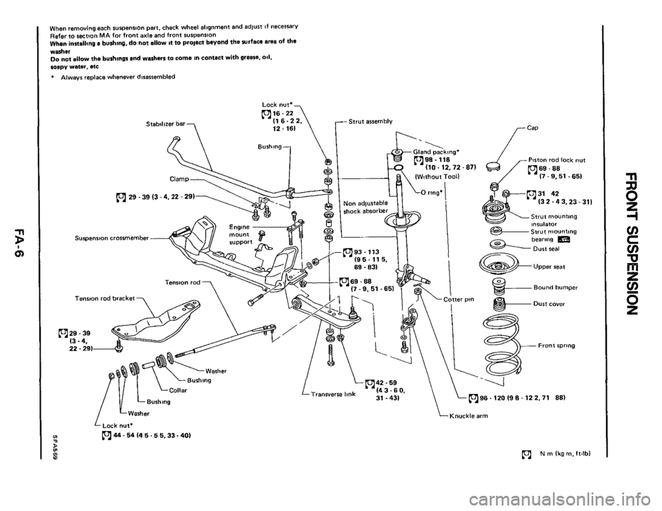
When removing each s~~pension part, check wheel allgnrnent and adlust If necessary
Refer to section MA for front axle and front suspension When innalling a bushing, do not allow It to prolect beyond the surface ares of the
warhsr
Do not allow the bushings and washers to come in conlact with grease. 011. soapy water. etc
* Always replace whenever disassembled
Strut assembly
Piston rad lock nut
(3 2.4 3,23 - 311
Strut mounting
Suspension crossmember
Tension rod bracket
m29-39
(3 - 4. 22.291
m96.120 19 8.12 2.71 881 Transverse link
LWasher
Lock nut*
m44- 54 (4 5.6 5,33- 40) m n
Knuckle arm
(c1 N m (kg m. ft-lbl g 0 10
n
8
z
-I
v)
c
v)
'cl
v)
z
e
5
Page 7 of 24
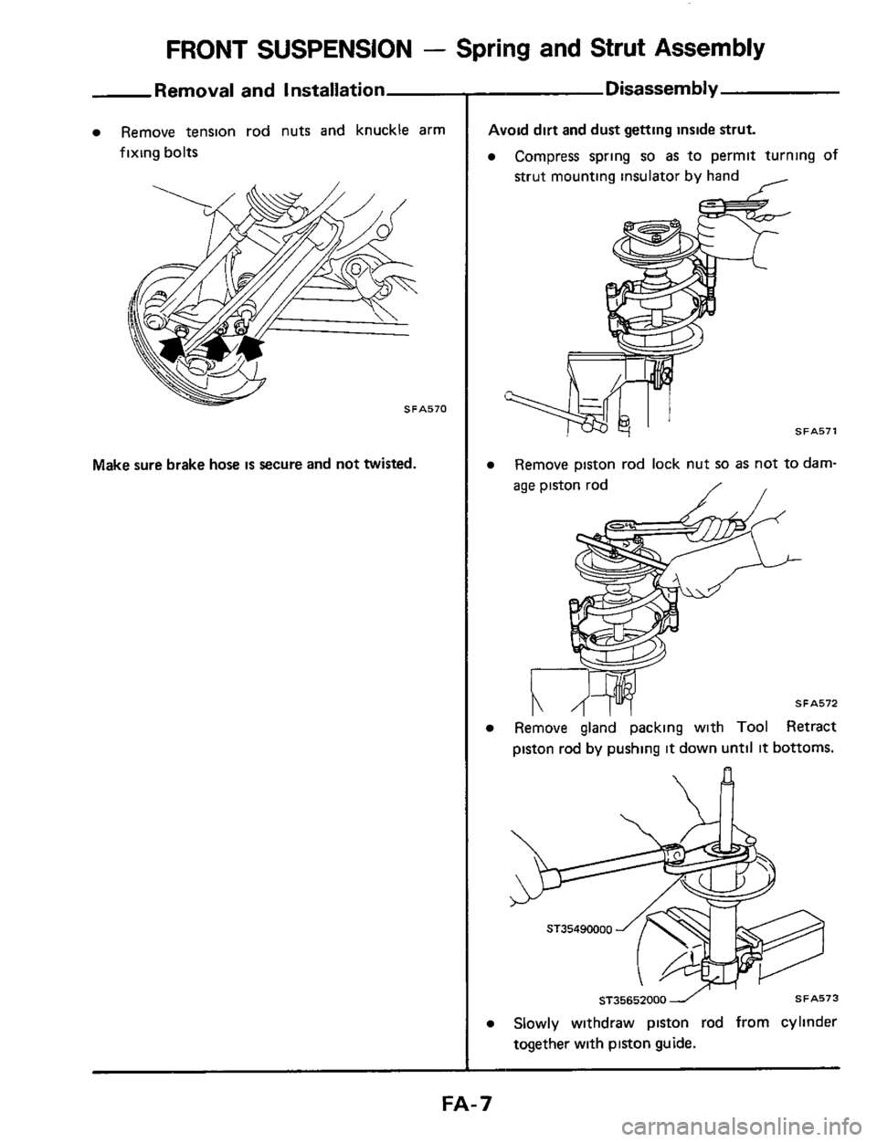
FRONT SUSPENSION - Spring and Strut Assembly
Removal and Installation
Remove tension rod nuts and knuckle arm
fixing bolts
Make sure brake hose is secure and not twisted.
Disassembly
Avoid dirt and dust getting inside strut.
Compress spring so as to permit turning of
strut mounting insulator by hand I
SFA571
Remove piston rod lock nut so as not to darn-
age piston rod / /
Remove gland packing with Tool Retract
piston rod
by pushing it down until it bottoms.
n
ST35652000 1 SFA573
Slowly withdraw piston rod from cylinder
together with piston guide.
FA- 7
Page 15 of 24
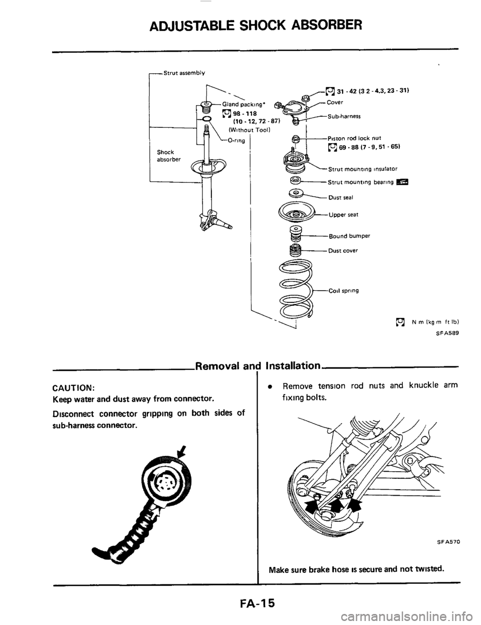
ADJUSTABLE SHOCK ABSORBER
rStwt assembly
31 -42 (3 2 -4.3,23- 31)
(Without Tool1
P~rton rod lock nut
69 .88 (7 .9.51 .651
Strut mounting tnsulator
Strut mounting bearing m
31 -42 (3 2 -4.3.23- 31)
Strut mounting tnsulator
im
Shock
absorber
Oust seal
Upper seat
Bound bumper
I e- Dust cover
ie
N m Ikg m ft Ibl
SA589
Removal ar
CAUTION:
Keep water and dust away from connector.
Disconnect connector grlpplng
on both sides of
sub-harness connector.
Installation
Remove tenslon rod nuts and knuckle arm
fixing bolts.
SFA570
Make sure brake hose IS secure and not twisted.
FA-I 5
Page 20 of 24
ADJUSTABLE SHOCK ABSORBER
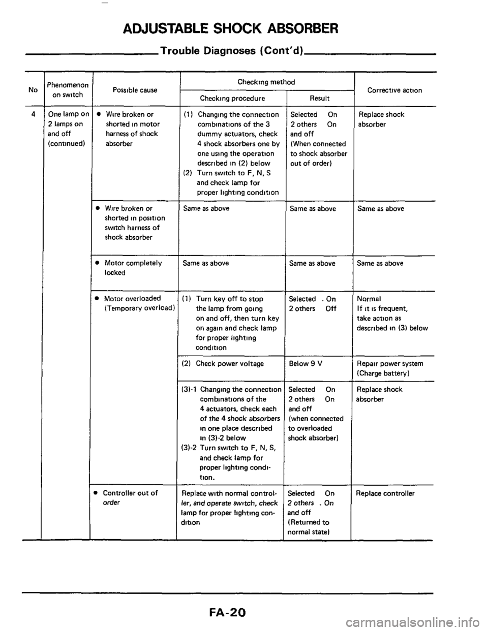
Trouble Diagnoses (Cont'd)
'henomenoi on switch
One lamp o
2 lamps on
rnd off
[continued)
Possible cause ~
Wire
broken or
shorted in motor
harness of shock
absorber
b Wire broken or
shorted in position
switch harness of
shock absorber
1 Motor completely
locked
1 Motor overloaded
(Temporary overload
Controller out of
order
Checking method
Checking procedure
(1 I Changing the connection
combinations
of the 3
dummy actuators, check
4 shock absorbers one by
one using the operation
described
in (2) below
(2) Turn switch to F, N, S
and check lamp for
proper lighting condition
Same as above
Same as above
(1) Turn key off to stop
the lamp from going
on
and off, then turn key
on again and check lamp
for proper lighting
condition
12) Check power voltage
:3)-1 Changing the connectior
combinations of the
4 actuators, check each
of the
4 shock absorbers
in one place described
in 131-2 below
13j-2 Turn switch to F, N, S,
and check lamp for
proper lighting condi-
tion.
Replace with normal control-
er, and operate switch, check
amp for proper lighting con-
jition
Result
Selected On
2others On
and
off
(When connected
to shock absorber
out of order)
Same as above
Same as above
Selected . On
2others
Off
Below 9 V
Selected On
2others On
and off
(when connected
to overloaded
shock absorber1
jelected On
Zothers
. On
3nd off
I Returned to
iormal state)
Corrective action
Replace shock
absorber
Same as above
Same as above
Normal
If it is frequent,
take action as
described in (3) below
Repair power system
(Charge battery)
Replace shock
absorber
Replace controller
FA-20
Page 23 of 24
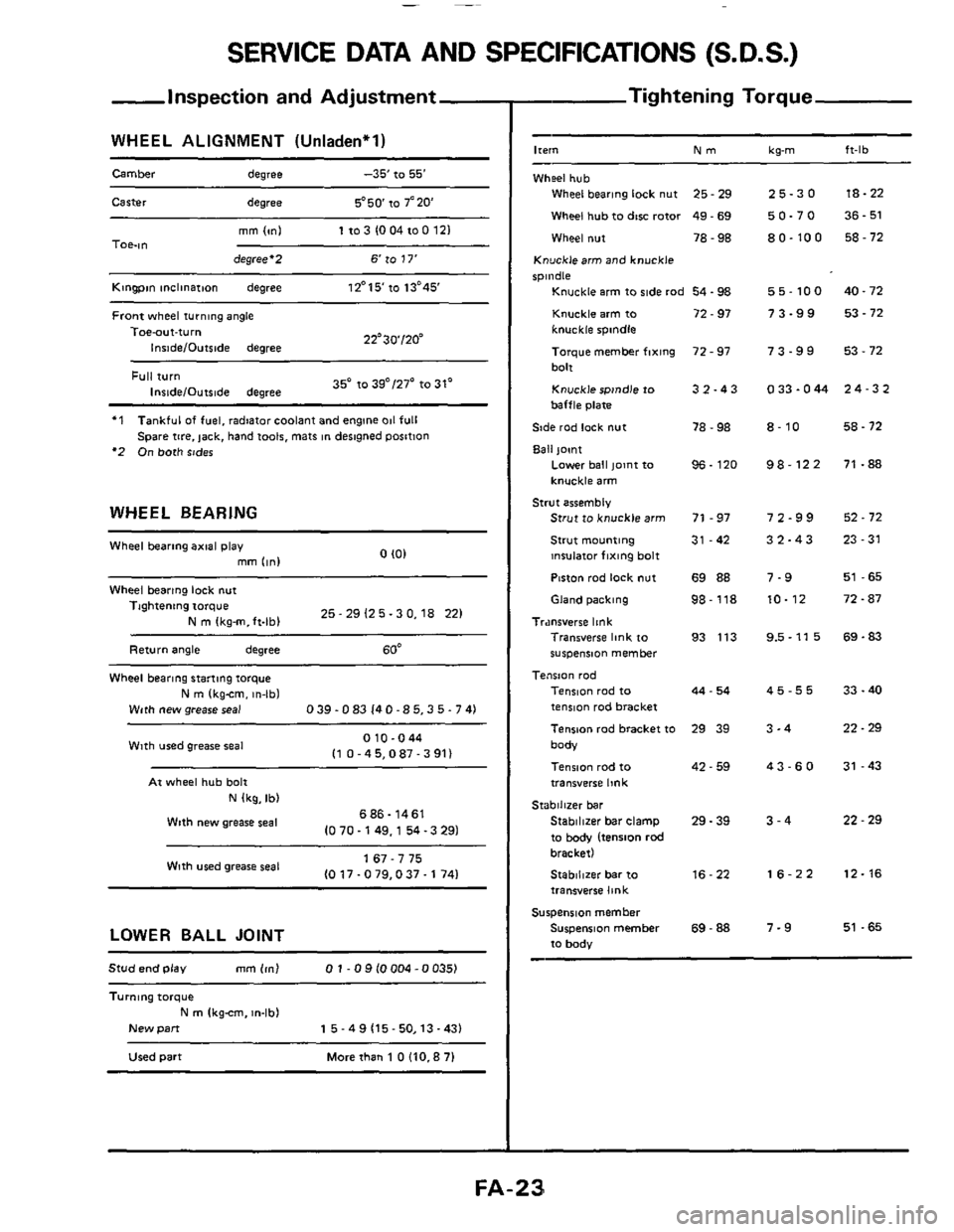
SERVICE DATA AND SPECIFICATIONS (S.D.S.)
-Inspection and Adjustment
WHEEL ALIGNMENT (Unladen'l)
Camber degree -35' to 55'
Carter degree 5'50 to 7'20
mm lml 1103 1004100 121 TOe-ltl degree'2 6 to 17'
Kingpin inclinatmn degree 12'15'10 13'45'
Front wheel turning angle
22'30'120" Toe-aut-turn
Inside/Outslde degree
35' to 39"/27' to 31' Full turn InridelOutslde degree
'1
'2 On both sides
Tankful of fuel, radiator coolant and engine 011 full
Spare
tire. jack, hand t001s. mats in desngned position
WHEEL BEARING
0 I01 Wheel bearing axial play
mm (in1
Wheel bearing lock nut
25 - 29 12 5.3 0,18 221 Tightening torque
N m Ikg-m.ft-lbl
Return angle degree 60'
Wheel bearing stanmg torque
N m (kgcm. in-lbl
With new grease seal 0 39.0 83 14 0 -8 5,3 5.7 41
010-044 I1 0 -45,087 - 3 911 Wlth used grease seal
At wheel hub bolt
N (kg, Ib)
686- 1461
10 70.149,l 54 -3 291 Wtth new grease seal
1 67 - 7 75
10 17.0 79,037.1 741 With wed grease seal
LOWER BALL JOINT
Stud end play mm 1ml 0 1 - 0 9 10004 -0 0351
Turnlng torque
New pan
N m Ikgcm. m-lb)
1 5 - 4 9 (15- 50,13 -431
Used part Morethan 1 OllO.87l
- Tightening Torque
-
Ire," Nm kg-m ft-lb
Wheel hub
Wheel bearing lock nut 25 - 29
Wheel hub to dtw rotor 49 - 69
Wheel nut 78 - 98
Knucklearm and knuckle
spindle
Knuckle arm to ride rod 54.98
Knuckle arm to 72 - 97
knuckle spindle
Toique member fixing
bolt
Knuckle spindle to
baffle plate
Side rod lock
nut
Ball joint
72 - 97
3 2.4 3
78 - 98
Lower ball pint to
knuckle arm
Strut to knuckle arm 71 - 97
Strut mounting 31 -42
insulator fixing bolt
Piston rod
lock nut 69 88
96. 120
Strut assembly
Gland packing 98-118
Tr.mrverre link Transverse link to 93 113
wspeniion member
Tension rod Tension rod to
tenmn rod bracket
Tenson rad bracket
to 29 39
body
Tension rod
to
transverse link
Stabilizer bar clamp 29. 39
to body (tension rod bracket)
Stablllzer bar to 16-22
transverse link
Surpenrlon member
Suspension member
69 - 88
to body
44 - 54
42 - 59
Stabilizer bar
25-30
50-70
80-100
55-100
73-99
73-99
0 33.044
8-10
98-122
72-99
32-43
7-9
10-12
9.5-11 5
45-55
3-4
43-60
3-4
16-22
7-9
18-22
36
- 51
58
- 72
40.72 53
- 72
53 - 72
24-32
58.72
71 -88
52.72
23-31
51 -65
72.87
69.83
33 - 40
22.29
31 -43
22 - 29
12-16
51 -65