NISSAN ALMERA 2001 Service Manual
ALMERA 2001
NISSAN
NISSAN
https://www.carmanualsonline.info/img/5/57348/w960_57348-0.png
NISSAN ALMERA 2001 Service Manual
Trending: height, window, change wheel, driver seat adjustment, phone, bolt pattern, lights
Page 1201 of 2898
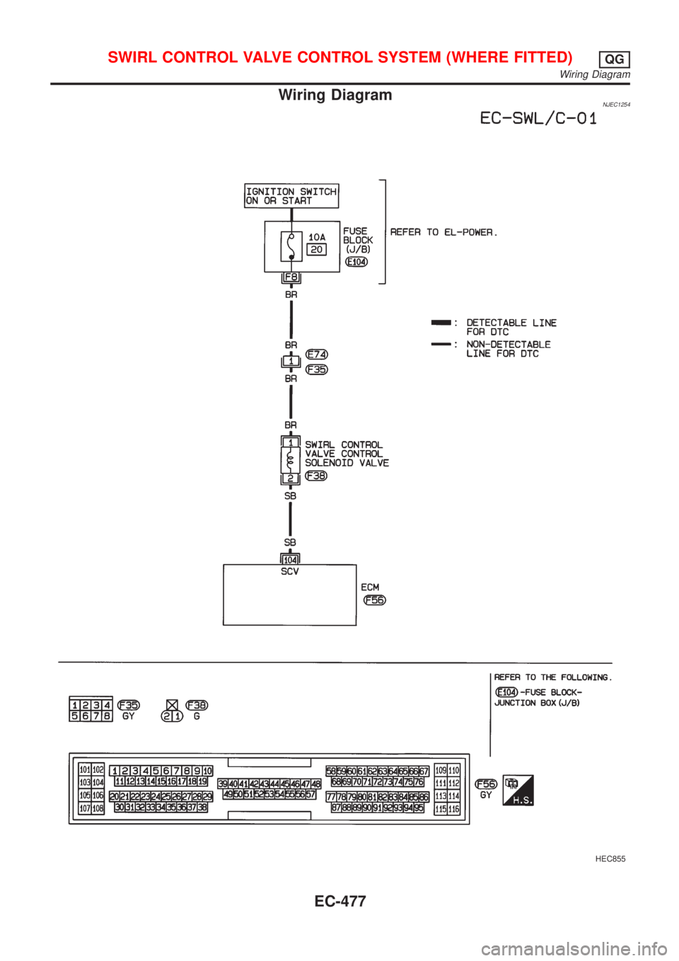
Wiring DiagramNJEC1254
HEC855
SWIRL CONTROL VALVE CONTROL SYSTEM (WHERE FITTED)QG
Wiring Diagram
EC-477
Page 1202 of 2898
Diagnostic ProcedureNJEC1255
1 INSPECTION START
Do you have CONSULT-II?
YesorNo
Ye s©GO TO 2.
No©GO TO 3.
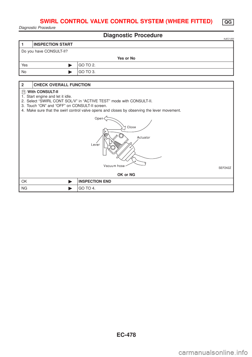
2 CHECK OVERALL FUNCTION
With CONSULT-II
1. Start engine and let it idle.
2. Select ªSWIRL CONT SOL/Vº in ªACTIVE TESTº mode with CONSULT-II.
3. Touch ªONº and ªOFFº on CONSULT-II screen.
4. Make sure that the swirl control valve opens and closes by observing the lever movement.
SEF242Z
OK or NG
OK©INSPECTION END
NG©GO TO 4.
SWIRL CONTROL VALVE CONTROL SYSTEM (WHERE FITTED)QG
Diagnostic Procedure
EC-478
Page 1203 of 2898
3 CHECK OVERALL FUNCTION
Without CONSULT-II
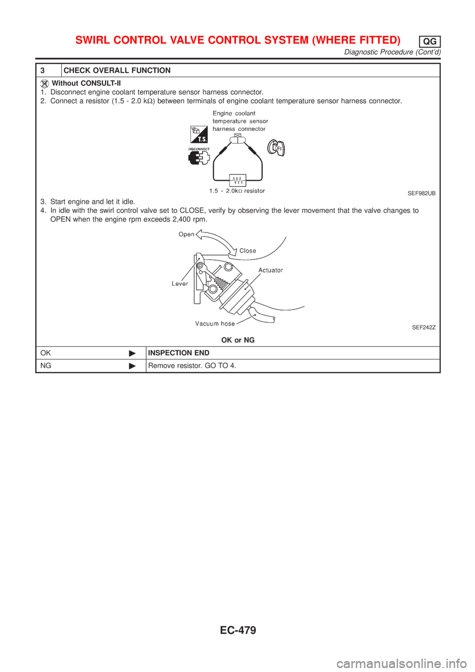
1. Disconnect engine coolant temperature sensor harness connector.
2. Connect a resistor (1.5 - 2.0 kW) between terminals of engine coolant temperature sensor harness connector.
SEF982UB
3. Start engine and let it idle.
4. In idle with the swirl control valve set to CLOSE, verify by observing the lever movement that the valve changes to
OPEN when the engine rpm exceeds 2,400 rpm.
SEF242Z
OK or NG
OK©INSPECTION END
NG©Remove resistor. GO TO 4.
SWIRL CONTROL VALVE CONTROL SYSTEM (WHERE FITTED)QG
Diagnostic Procedure (Cont'd)
EC-479
Page 1204 of 2898
4 CHECK VACUUM EXISTENCE
With CONSULT-II
1. Reconnect the disconnected harness connectors.
2. Start engine and let it idle.
3. Remove vacuum hose connected to swirl control valve actuator.
4. Select ªSWIRL CONT SOL/Vº in ªACTIVE TESTº mode with CONSULT-II.
5. Touch ªONº and ªOFFº on CONSULT-II screen.
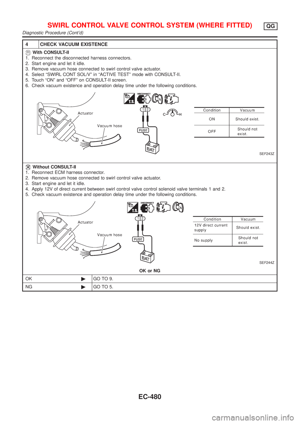
6. Check vacuum existence and operation delay time under the following conditions.
SEF243Z
Without CONSULT-II
1. Reconnect ECM harness connector.
2. Remove vacuum hose connected to swirl control valve actuator.
3. Start engine and let it idle.
4. Apply 12V of direct current between swirl control valve control solenoid valve terminals 1 and 2.
5. Check vacuum existence and operation delay time under the following conditions.
SEF244Z
OK or NG
OK©GO TO 9.
NG©GO TO 5.
SWIRL CONTROL VALVE CONTROL SYSTEM (WHERE FITTED)QG
Diagnostic Procedure (Cont'd)
EC-480
Page 1205 of 2898
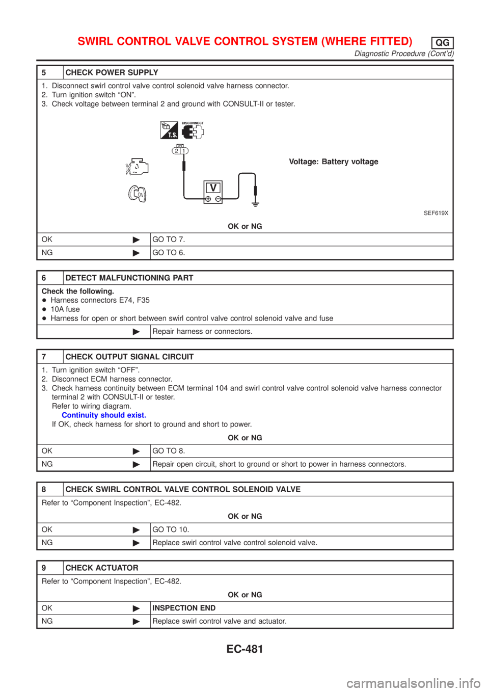
5 CHECK POWER SUPPLY
1. Disconnect swirl control valve control solenoid valve harness connector.
2. Turn ignition switch ªONº.
3. Check voltage between terminal 2 and ground with CONSULT-II or tester.
SEF619X
OK or NG
OK©GO TO 7.
NG©GO TO 6.
6 DETECT MALFUNCTIONING PART
Check the following.
+Harness connectors E74, F35
+10A fuse
+Harness for open or short between swirl control valve control solenoid valve and fuse
©Repair harness or connectors.
7 CHECK OUTPUT SIGNAL CIRCUIT
1. Turn ignition switch ªOFFº.
2. Disconnect ECM harness connector.
3. Check harness continuity between ECM terminal 104 and swirl control valve control solenoid valve harness connector
terminal 2 with CONSULT-II or tester.
Refer to wiring diagram.
Continuity should exist.
If OK, check harness for short to ground and short to power.
OK or NG
OK©GO TO 8.
NG©Repair open circuit, short to ground or short to power in harness connectors.
8 CHECK SWIRL CONTROL VALVE CONTROL SOLENOID VALVE
Refer to ªComponent Inspectionº, EC-482.
OK or NG
OK©GO TO 10.
NG©Replace swirl control valve control solenoid valve.
9 CHECK ACTUATOR
Refer to ªComponent Inspectionº, EC-482.
OK or NG
OK©INSPECTION END
NG©Replace swirl control valve and actuator.
SWIRL CONTROL VALVE CONTROL SYSTEM (WHERE FITTED)QG
Diagnostic Procedure (Cont'd)
EC-481
Page 1206 of 2898
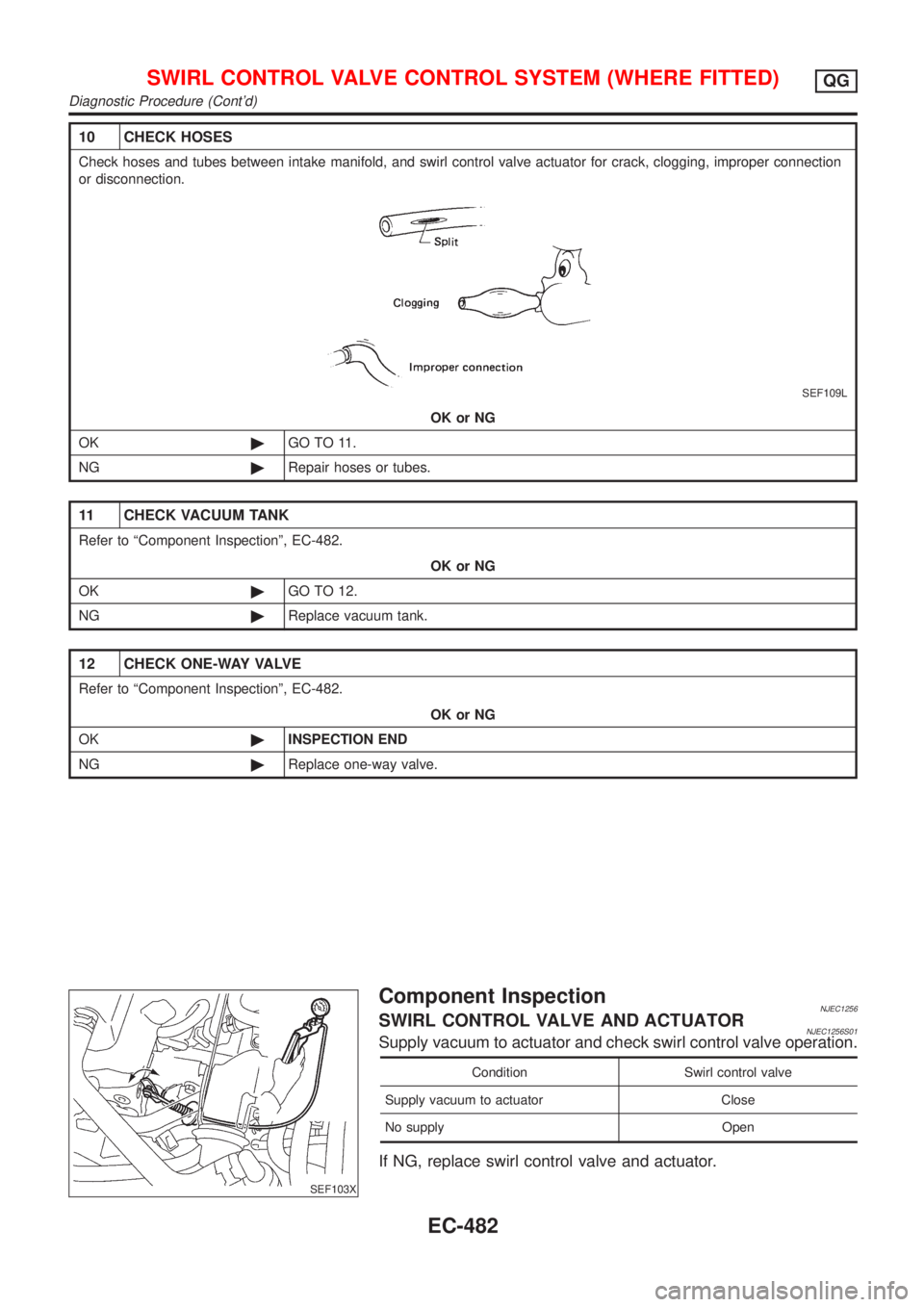
10 CHECK HOSES
Check hoses and tubes between intake manifold, and swirl control valve actuator for crack, clogging, improper connection
or disconnection.
SEF109L
OK or NG
OK©GO TO 11.
NG©Repair hoses or tubes.
11 CHECK VACUUM TANK
Refer to ªComponent Inspectionº, EC-482.
OK or NG
OK©GO TO 12.
NG©Replace vacuum tank.
12 CHECK ONE-WAY VALVE
Refer to ªComponent Inspectionº, EC-482.
OK or NG
OK©INSPECTION END
NG©Replace one-way valve.
SEF103X
Component InspectionNJEC1256SWIRL CONTROL VALVE AND ACTUATORNJEC1256S01Supply vacuum to actuator and check swirl control valve operation.
Condition Swirl control valve
Supply vacuum to actuator Close
No supply Open
If NG, replace swirl control valve and actuator.
SWIRL CONTROL VALVE CONTROL SYSTEM (WHERE FITTED)QG
Diagnostic Procedure (Cont'd)
EC-482
Page 1207 of 2898
SEF105X
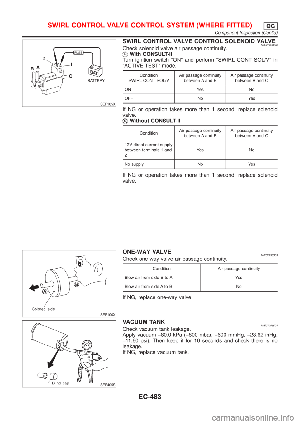
SWIRL CONTROL VALVE CONTROL SOLENOID VALVENJEC1256S02Check solenoid valve air passage continuity.
With CONSULT-II
Turn ignition switch ªONº and perform ªSWIRL CONT SOL/Vº in
ªACTIVE TESTº mode.
Condition
SWIRL CONT SOL/VAir passage continuity
between A and BAir passage continuity
between A and C
ON Yes No
OFF No Yes
If NG or operation takes more than 1 second, replace solenoid
valve.
Without CONSULT-II
ConditionAir passage continuity
between A and BAir passage continuity
between A and C
12V direct current supply
between terminals 1 and
2Ye s N o
No supply No Yes
If NG or operation takes more than 1 second, replace solenoid
valve.
SEF106X
ONE-WAY VALVENJEC1256S03Check one-way valve air passage continuity.
Condition Air passage continuity
Blow air from side B to A Yes
Blow air from side A to B No
If NG, replace one-way valve.
SEF405S
VACUUM TANKNJEC1256S04Check vacuum tank leakage.
Apply vacuum þ80.0 kPa (þ800 mbar, þ600 mmHg, þ23.62 inHg,
þ11.60 psi). Then keep it for 10 seconds and check there is no
leakage.
If NG, replace vacuum tank.
SWIRL CONTROL VALVE CONTROL SYSTEM (WHERE FITTED)QG
Component Inspection (Cont'd)
EC-483
Page 1208 of 2898
SEF058X
JEF835Z
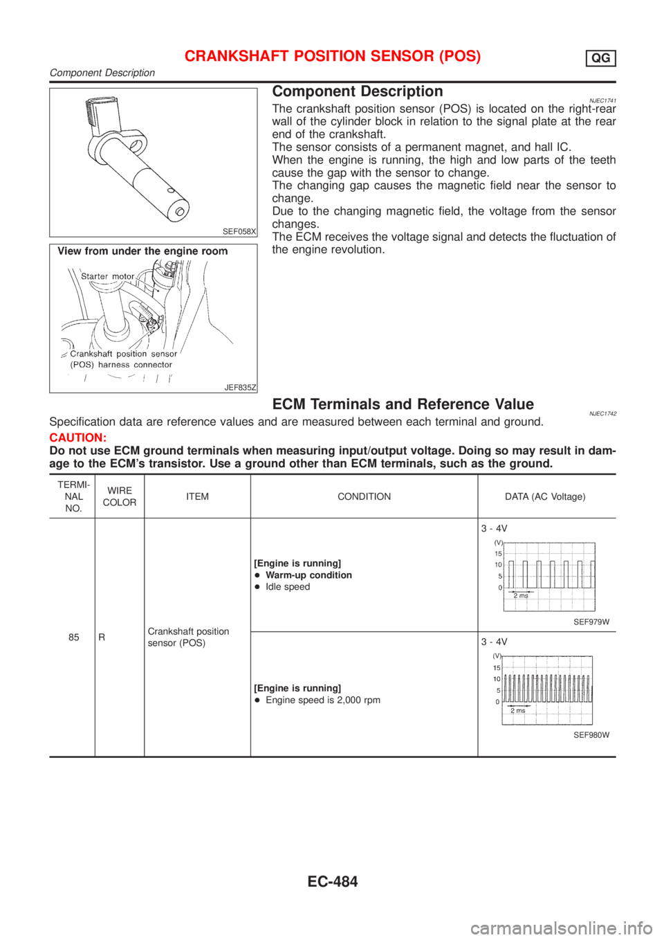
Component DescriptionNJEC1741The crankshaft position sensor (POS) is located on the right-rear
wall of the cylinder block in relation to the signal plate at the rear
end of the crankshaft.
The sensor consists of a permanent magnet, and hall IC.
When the engine is running, the high and low parts of the teeth
cause the gap with the sensor to change.
The changing gap causes the magnetic field near the sensor to
change.
Due to the changing magnetic field, the voltage from the sensor
changes.
The ECM receives the voltage signal and detects the fluctuation of
the engine revolution.
ECM Terminals and Reference ValueNJEC1742Specification data are reference values and are measured between each terminal and ground.
CAUTION:
Do not use ECM ground terminals when measuring input/output voltage. Doing so may result in dam-
age to the ECM's transistor. Use a ground other than ECM terminals, such as the ground.
TERMI-
NAL
NO.WIRE
COLORITEM CONDITION DATA (AC Voltage)
85 RCrankshaft position
sensor (POS)[Engine is running]
+Warm-up condition
+Idle speed3-4V
SEF979W
[Engine is running]
+Engine speed is 2,000 rpm3-4V
SEF980W
CRANKSHAFT POSITION SENSOR (POS)QG
Component Description
EC-484
Page 1209 of 2898
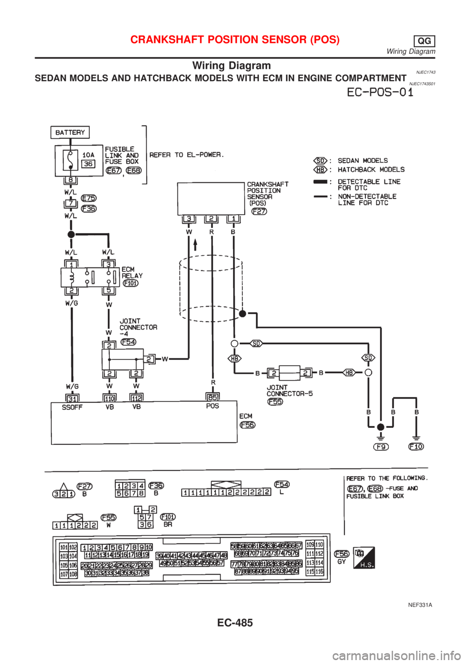
Wiring DiagramNJEC1743SEDAN MODELS AND HATCHBACK MODELS WITH ECM IN ENGINE COMPARTMENTNJEC1743S01
NEF331A
CRANKSHAFT POSITION SENSOR (POS)QG
Wiring Diagram
EC-485
Page 1210 of 2898
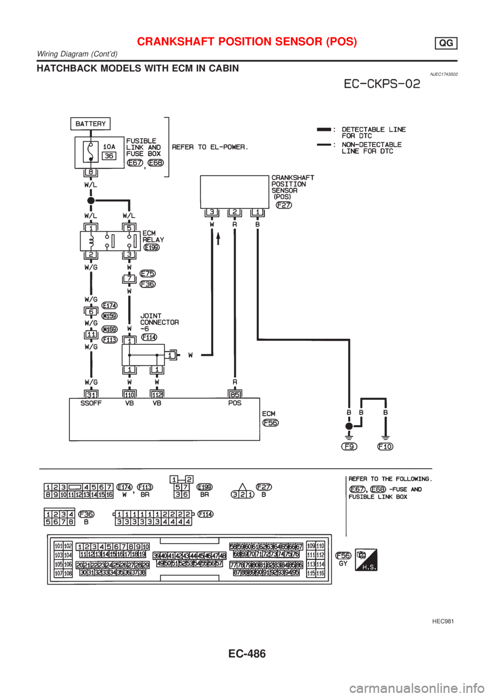
HATCHBACK MODELS WITH ECM IN CABINNJEC1743S02
HEC981
CRANKSHAFT POSITION SENSOR (POS)QG
Wiring Diagram (Cont'd)
EC-486
Trending: compression ratio, coolant reservoir, seat memory, radiator, heater, flat tire, wheel alignment
