NISSAN ALMERA 2001 Service Manual
Manufacturer: NISSAN, Model Year: 2001, Model line: ALMERA, Model: NISSAN ALMERA 2001Pages: 2898, PDF Size: 60.76 MB
Page 1221 of 2898
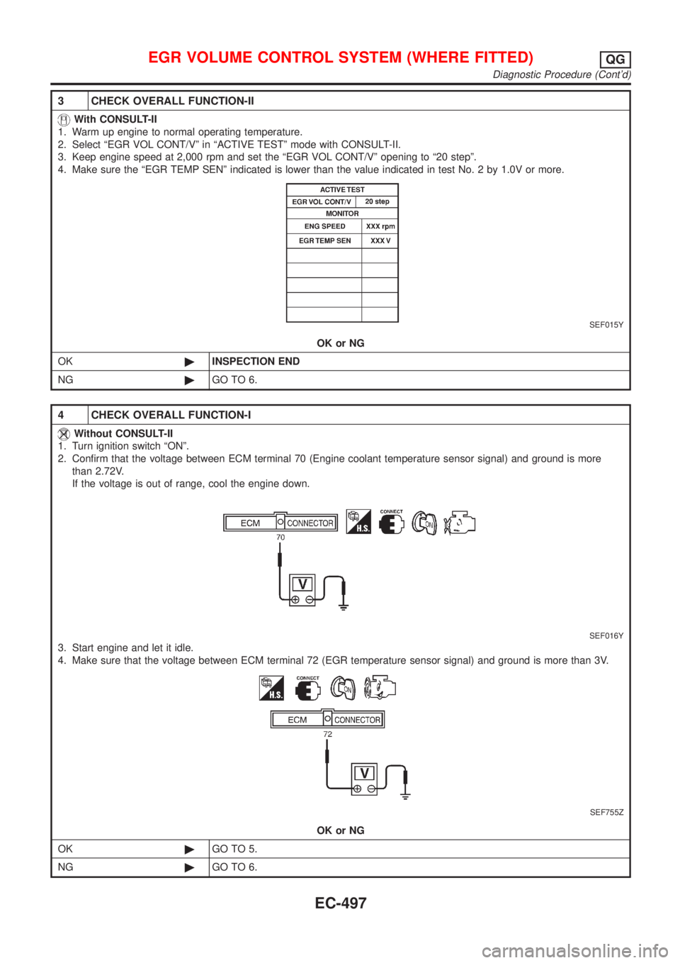
3 CHECK OVERALL FUNCTION-II
With CONSULT-II
1. Warm up engine to normal operating temperature.
2. Select ªEGR VOL CONT/Vº in ªACTIVE TESTº mode with CONSULT-II.
3. Keep engine speed at 2,000 rpm and set the ªEGR VOL CONT/Vº opening to ª20 stepº.
4. Make sure the ªEGR TEMP SENº indicated is lower than the value indicated in test No. 2 by 1.0V or more.
SEF015Y
OK or NG
OK©INSPECTION END
NG©GO TO 6.
4 CHECK OVERALL FUNCTION-I
Without CONSULT-II
1. Turn ignition switch ªONº.
2. Confirm that the voltage between ECM terminal 70 (Engine coolant temperature sensor signal) and ground is more
than 2.72V.
If the voltage is out of range, cool the engine down.
SEF016Y
3. Start engine and let it idle.
4. Make sure that the voltage between ECM terminal 72 (EGR temperature sensor signal) and ground is more than 3V.
SEF755Z
OK or NG
OK©GO TO 5.
NG©GO TO 6.
EGR VOLUME CONTROL SYSTEM (WHERE FITTED)QG
Diagnostic Procedure (Cont'd)
EC-497
Page 1222 of 2898
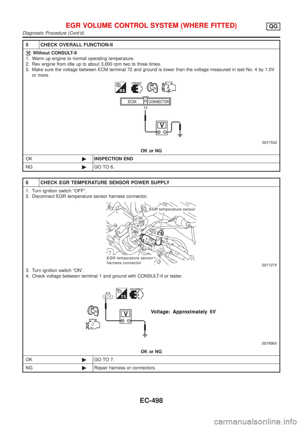
5 CHECK OVERALL FUNCTION-II
Without CONSULT-II
1. Warm up engine to normal operating temperature.
2. Rev engine from idle up to about 3,000 rpm two to three times.
3. Make sure the voltage between ECM terminal 72 and ground is lower than the voltage measured in test No. 4 by 1.0V
or more.
SEF755Z
OK or NG
OK©INSPECTION END
NG©GO TO 6.
6 CHECK EGR TEMPERATURE SENSOR POWER SUPPLY
1. Turn ignition switch ªOFFº.
2. Disconnect EGR temperature sensor harness connector.
SEF127X
3. Turn ignition switch ªONº.
4. Check voltage between terminal 1 and ground with CONSULT-II or tester.
SEF896X
OK or NG
OK©GO TO 7.
NG©Repair harness or connectors.
EGR VOLUME CONTROL SYSTEM (WHERE FITTED)QG
Diagnostic Procedure (Cont'd)
EC-498
Page 1223 of 2898
7 CHECK EGR TEMPERATURE SENSOR GROUND CIRCUIT
1. Turn ignition switch ªOFFº.
2. Check harness continuity between EGR temperature sensor harness terminal 2 and engine ground.
Refer to wiring diagram.
Continuity should exist.
3. Also check harness for short to ground and short to power.
OK or NG
OK©GO TO 9.
NG©GO TO 8.
8 DETECT MALFUNCTIONING PART
Check the following.
+Harness for open or short between EGR temperature sensor and ECM
+Harness for open or short between TCM (Transmission Control Module) and ECM
+Joint connector-3 (If so equipped)
+Joint connector-6 (If so equipped)
©Repair open circuit or short to ground or short to power in harness or connector.
9 CHECK EGR TEMPERATURE SENSOR
Refer to ªComponent Inspectionº, EC-502.
OK or NG
OK©GO TO 10.
NG©Replace EGR temperature sensor.
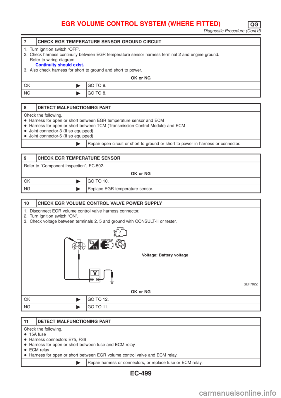
10 CHECK EGR VOLUME CONTROL VALVE POWER SUPPLY
1. Disconnect EGR volume control valve harness connector.
2. Turn ignition switch ªONº.
3. Check voltage between terminals 2, 5 and ground with CONSULT-II or tester.
SEF782Z
OK or NG
OK©GO TO 12.
NG©GO TO 11.
11 DETECT MALFUNCTIONING PART
Check the following.
+15A fuse
+Harness connectors E75, F36
+Harness for open or short between fuse and ECM relay
+ECM relay
+Harness for open or short between EGR volume control valve and ECM relay.
©Repair harness or connectors, or replace fuse or ECM relay.
EGR VOLUME CONTROL SYSTEM (WHERE FITTED)QG
Diagnostic Procedure (Cont'd)
EC-499
Page 1224 of 2898
12 CHECK OUTPUT SIGNAL CIRCUIT
1. Turn ignition switch ªOFFº.
2. Disconnect ECM harness connector.
3. Check harness continuity between
ECM terminal 8 and EGR volume control valve terminal 1,
ECM terminal 9 and EGR volume control valve terminal 4,
ECM terminal 17 and EGR volume control valve terminal 3,
ECM terminal 18 and EGR volume control valve terminal 6.
Refer to wiring diagram.
Continuity should exist.
4. Also check harness for short to ground and short to power.
OK or NG
OK©GO TO 13.
NG©Repair open circuit, short to ground or short to power in harness connectors.
13 CHECK EGR PASSAGE
Check EGR passage for clogging and cracks.
OK or NG
OK©GO TO 14.
NG©Repair or replace EGR passage.
14 CHECK EGR VOLUME CONTROL VALVE
Refer to ªCOMPONENT INSPECTIONº, EC-501.
OK or NG
OK©GO TO 15.
NG©Replace EGR volume control valve.
15 CHECK INTERMITTENT INCIDENT
Perform ªTROUBLE DIAGNOSIS FOR INTERMITTENT INCIDENTº, EC-177.
©INSPECTION END
EGR VOLUME CONTROL SYSTEM (WHERE FITTED)QG
Diagnostic Procedure (Cont'd)
EC-500
Page 1225 of 2898
SEF069X
SEF605Y
SEF015Y
SEF560W
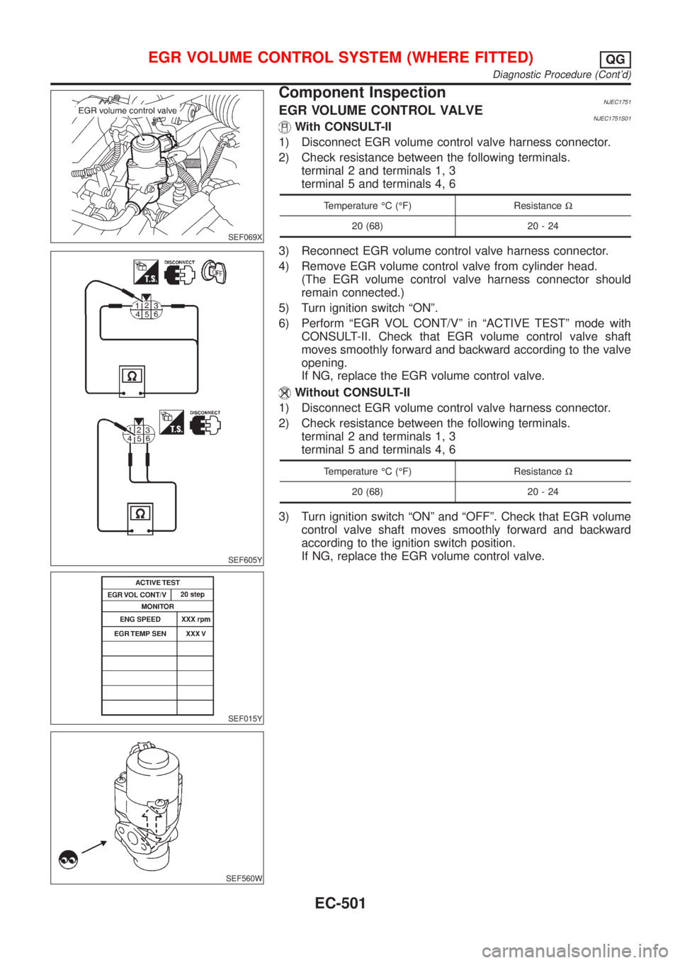
Component InspectionNJEC1751EGR VOLUME CONTROL VALVENJEC1751S01With CONSULT-II
1) Disconnect EGR volume control valve harness connector.
2) Check resistance between the following terminals.
terminal 2 and terminals 1, 3
terminal 5 and terminals 4, 6
Temperature ÉC (ÉF) ResistanceW
20 (68) 20 - 24
3) Reconnect EGR volume control valve harness connector.
4) Remove EGR volume control valve from cylinder head.
(The EGR volume control valve harness connector should
remain connected.)
5) Turn ignition switch ªONº.
6) Perform ªEGR VOL CONT/Vº in ªACTIVE TESTº mode with
CONSULT-II. Check that EGR volume control valve shaft
moves smoothly forward and backward according to the valve
opening.
If NG, replace the EGR volume control valve.
Without CONSULT-II
1) Disconnect EGR volume control valve harness connector.
2) Check resistance between the following terminals.
terminal 2 and terminals 1, 3
terminal 5 and terminals 4, 6
Temperature ÉC (ÉF) ResistanceW
20 (68) 20 - 24
3) Turn ignition switch ªONº and ªOFFº. Check that EGR volume
control valve shaft moves smoothly forward and backward
according to the ignition switch position.
If NG, replace the EGR volume control valve.
EGR VOLUME CONTROL SYSTEM (WHERE FITTED)QG
Diagnostic Procedure (Cont'd)
EC-501
Page 1226 of 2898
SEF611Y
SEF068X
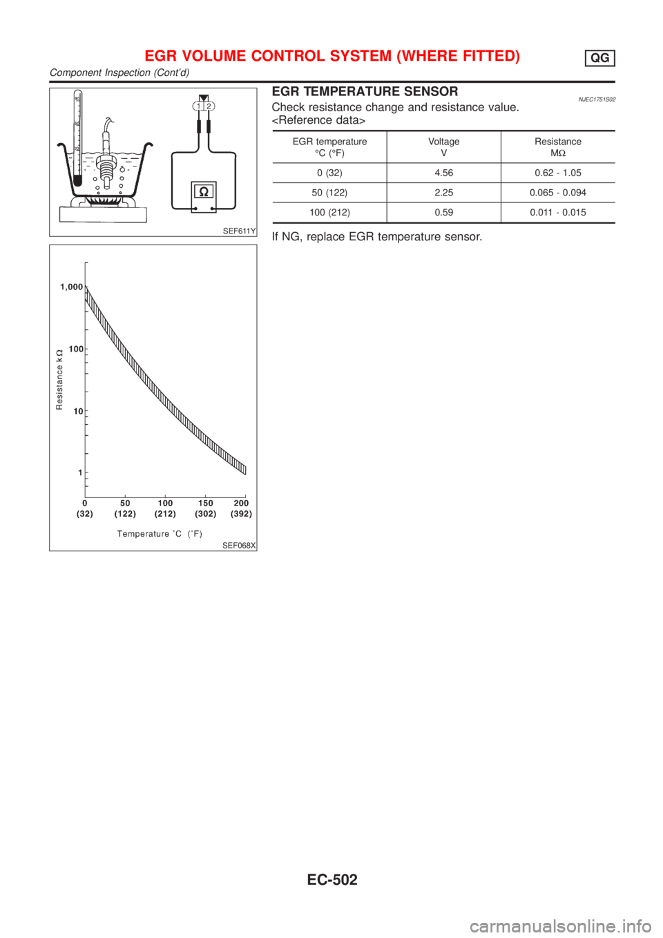
EGR TEMPERATURE SENSORNJEC1751S02Check resistance change and resistance value.
EGR temperature
ÉC (ÉF)Voltage
VResistance
MW
0 (32) 4.56 0.62 - 1.05
50 (122) 2.25 0.065 - 0.094
100 (212) 0.59 0.011 - 0.015
If NG, replace EGR temperature sensor.
EGR VOLUME CONTROL SYSTEM (WHERE FITTED)QG
Component Inspection (Cont'd)
EC-502
Page 1227 of 2898
DescriptionNJEC1752SYSTEM DESCRIPTIONNJEC1752S01
Sensor Input Signal to ECMECM func-
tionActuator
Crankshaft position sensor (POS) Engine speed
EVAP can-
ister purge
controlEVAP canister purge volume
control solenoid valve Camshaft position sensor (PHASE) Engine speed and cylinder number
Mass air flow sensor Amount of intake air
Engine coolant temperature sensor Engine coolant temperature
Battery Battery voltage
Ignition switch Start signal
Closed throttle position switch (If so
equipped)Closed throttle position
Throttle position sensor Throttle position
Heated oxygen sensor 1 (front)Density of oxygen in exhaust gas
(Mixture ratio feedback signal)
Vehicle speed sensor Vehicle speed
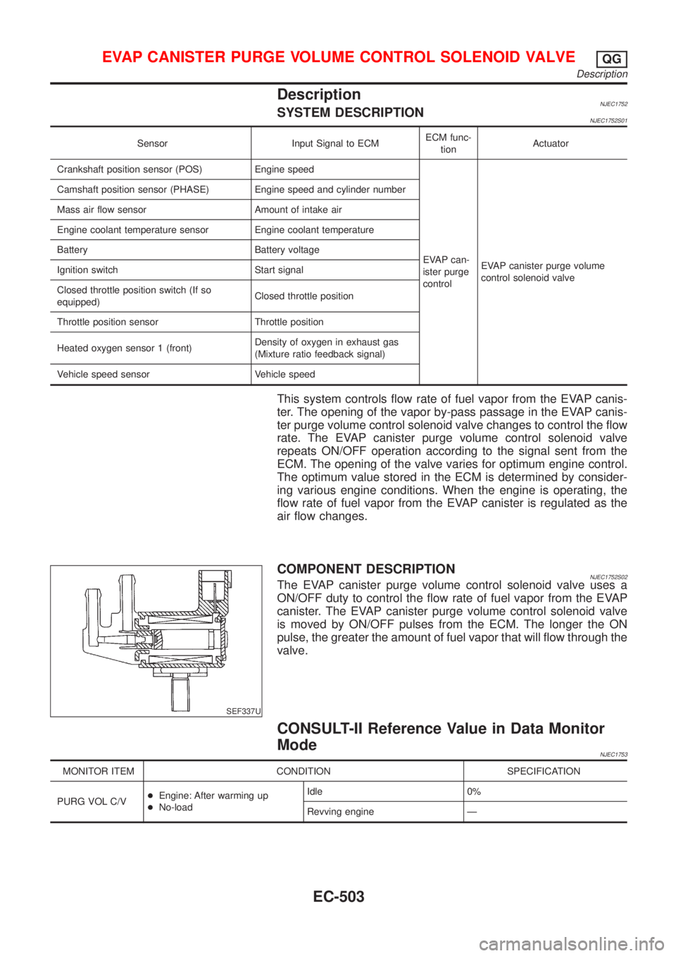
This system controls flow rate of fuel vapor from the EVAP canis-
ter. The opening of the vapor by-pass passage in the EVAP canis-
ter purge volume control solenoid valve changes to control the flow
rate. The EVAP canister purge volume control solenoid valve
repeats ON/OFF operation according to the signal sent from the
ECM. The opening of the valve varies for optimum engine control.
The optimum value stored in the ECM is determined by consider-
ing various engine conditions. When the engine is operating, the
flow rate of fuel vapor from the EVAP canister is regulated as the
air flow changes.
SEF337U
COMPONENT DESCRIPTIONNJEC1752S02The EVAP canister purge volume control solenoid valve uses a
ON/OFF duty to control the flow rate of fuel vapor from the EVAP
canister. The EVAP canister purge volume control solenoid valve
is moved by ON/OFF pulses from the ECM. The longer the ON
pulse, the greater the amount of fuel vapor that will flow through the
valve.
CONSULT-II Reference Value in Data Monitor
Mode
NJEC1753
MONITOR ITEM CONDITION SPECIFICATION
PURG VOL C/V+Engine: After warming up
+No-loadIdle 0%
Revving engine Ð
EVAP CANISTER PURGE VOLUME CONTROL SOLENOID VALVEQG
Description
EC-503
Page 1228 of 2898
ECM Terminals and Reference Value=NJEC1754Specification data are reference values and are measured between each terminal and ground.
CAUTION:
Do not use ECM ground terminals when measuring input/output voltage. Doing so may result in dam-
age to the ECM's transistor. Use a ground other than ECM terminals, such as the ground.
TER-
MINAL
NO.WIRE
COLORITEM CONDITION DATA (DC Voltage)
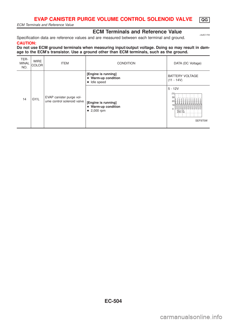
14 GY/LEVAP canister purge vol-
ume control solenoid valve[Engine is running]
+Warm-up condition
+Idle speedBATTERY VOLTAGE
(11 - 14V)
[Engine is running]
+Warm-up condition
+2,000 rpm5 - 12V
SEF975W
EVAP CANISTER PURGE VOLUME CONTROL SOLENOID VALVEQG
ECM Terminals and Reference Value
EC-504
Page 1229 of 2898
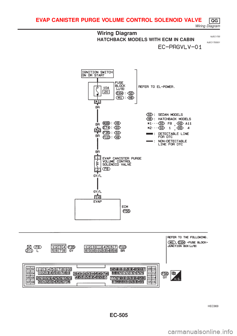
Wiring DiagramNJEC1755HATCHBACK MODELS WITH ECM IN CABINNJEC1755S01
HEC969
EVAP CANISTER PURGE VOLUME CONTROL SOLENOID VALVEQG
Wiring Diagram
EC-505
Page 1230 of 2898
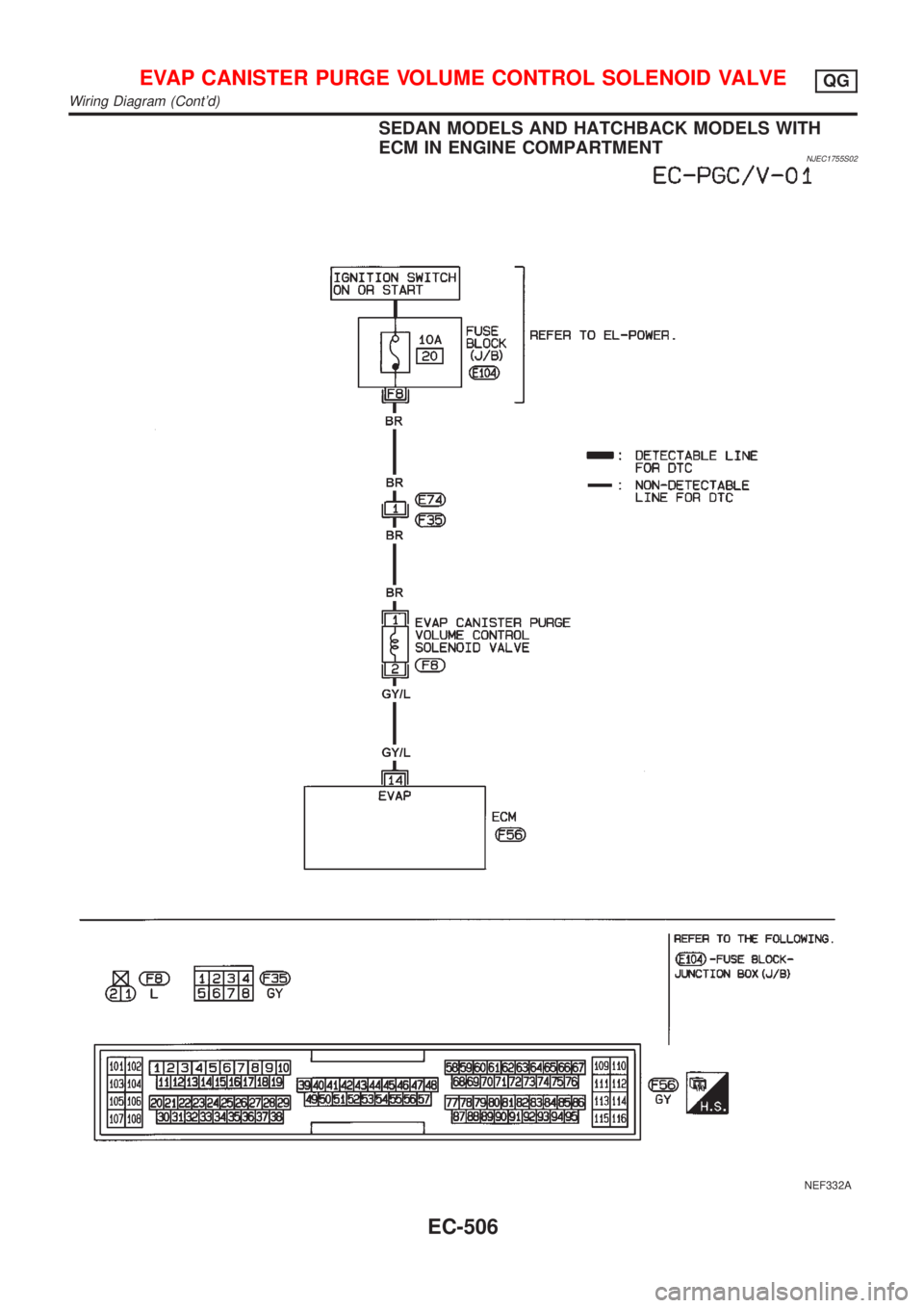
SEDAN MODELS AND HATCHBACK MODELS WITH
ECM IN ENGINE COMPARTMENT
NJEC1755S02
NEF332A
EVAP CANISTER PURGE VOLUME CONTROL SOLENOID VALVEQG
Wiring Diagram (Cont'd)
EC-506