NISSAN ALMERA 2001 Service Manual
ALMERA 2001
NISSAN
NISSAN
https://www.carmanualsonline.info/img/5/57348/w960_57348-0.png
NISSAN ALMERA 2001 Service Manual
Trending: length, tire type, heater, ABS, water pump, remove seats, oil pressure
Page 1261 of 2898
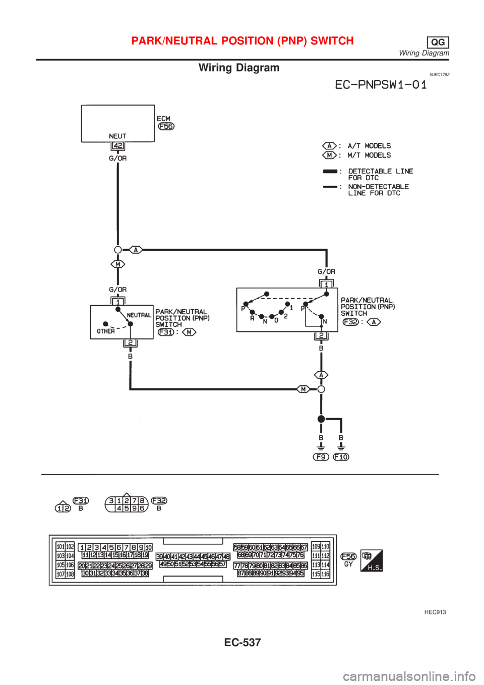
Wiring DiagramNJEC1782
HEC913
PARK/NEUTRAL POSITION (PNP) SWITCHQG
Wiring Diagram
EC-537
Page 1262 of 2898
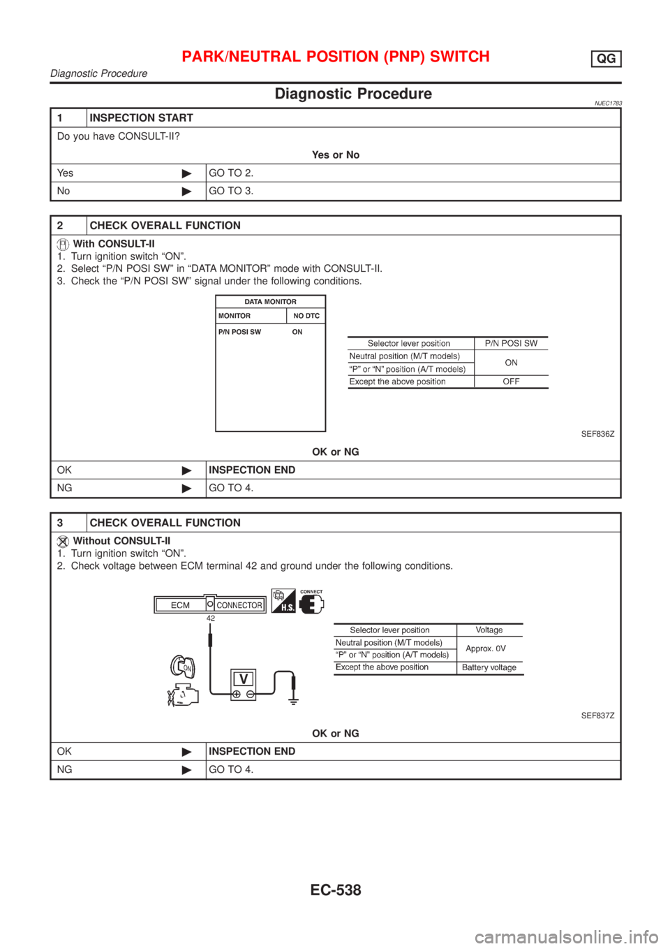
Diagnostic ProcedureNJEC1783
1 INSPECTION START
Do you have CONSULT-II?
YesorNo
Ye s©GO TO 2.
No©GO TO 3.
2 CHECK OVERALL FUNCTION
With CONSULT-II
1. Turn ignition switch ªONº.
2. Select ªP/N POSI SWº in ªDATA MONITORº mode with CONSULT-II.
3. Check the ªP/N POSI SWº signal under the following conditions.
SEF836Z
OK or NG
OK©INSPECTION END
NG©GO TO 4.
3 CHECK OVERALL FUNCTION
Without CONSULT-II
1. Turn ignition switch ªONº.
2. Check voltage between ECM terminal 42 and ground under the following conditions.
SEF837Z
OK or NG
OK©INSPECTION END
NG©GO TO 4.
PARK/NEUTRAL POSITION (PNP) SWITCHQG
Diagnostic Procedure
EC-538
Page 1263 of 2898
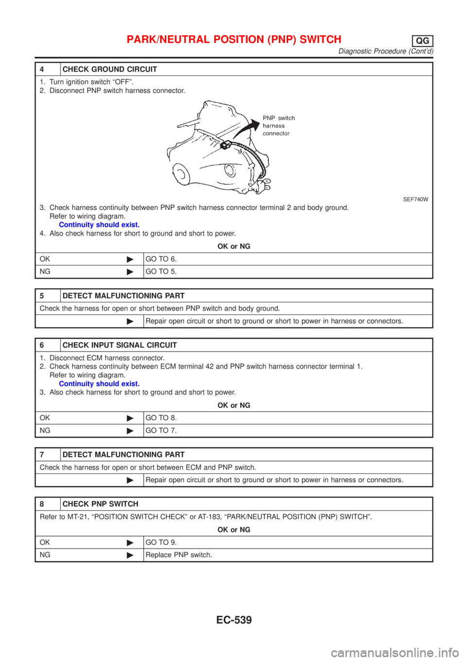
4 CHECK GROUND CIRCUIT
1. Turn ignition switch ªOFFº.
2. Disconnect PNP switch harness connector.
SEF740W
3. Check harness continuity between PNP switch harness connector terminal 2 and body ground.
Refer to wiring diagram.
Continuity should exist.
4. Also check harness for short to ground and short to power.
OK or NG
OK©GO TO 6.
NG©GO TO 5.
5 DETECT MALFUNCTIONING PART
Check the harness for open or short between PNP switch and body ground.
©Repair open circuit or short to ground or short to power in harness or connectors.
6 CHECK INPUT SIGNAL CIRCUIT
1. Disconnect ECM harness connector.
2. Check harness continuity between ECM terminal 42 and PNP switch harness connector terminal 1.
Refer to wiring diagram.
Continuity should exist.
3. Also check harness for short to ground and short to power.
OK or NG
OK©GO TO 8.
NG©GO TO 7.
7 DETECT MALFUNCTIONING PART
Check the harness for open or short between ECM and PNP switch.
©Repair open circuit or short to ground or short to power in harness or connectors.
8 CHECK PNP SWITCH
Refer to MT-21, ªPOSITION SWITCH CHECKº or AT-183, ªPARK/NEUTRAL POSITION (PNP) SWITCHº.
OK or NG
OK©GO TO 9.
NG©Replace PNP switch.
PARK/NEUTRAL POSITION (PNP) SWITCHQG
Diagnostic Procedure (Cont'd)
EC-539
Page 1264 of 2898
9 CHECK INTERMITTENT INCIDENT
Perform ªTROUBLE DIAGNOSIS FOR INTERMITTENT INCIDENTº, EC-177.
©INSPECTION END
PARK/NEUTRAL POSITION (PNP) SWITCHQG
Diagnostic Procedure (Cont'd)
EC-540
Page 1265 of 2898
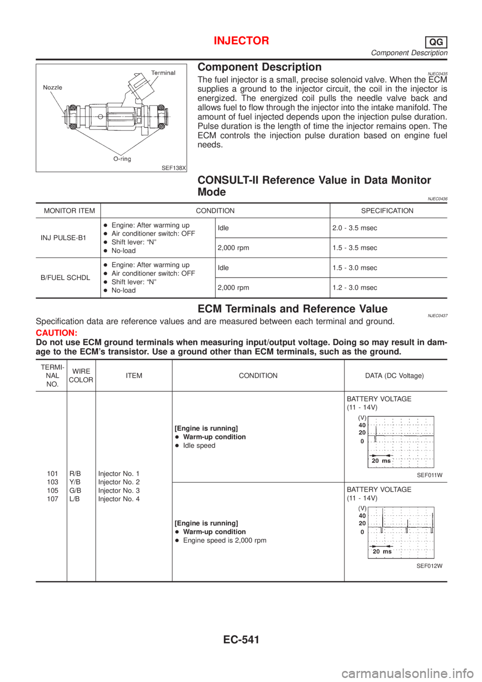
SEF138X
Component DescriptionNJEC0435The fuel injector is a small, precise solenoid valve. When the ECM
supplies a ground to the injector circuit, the coil in the injector is
energized. The energized coil pulls the needle valve back and
allows fuel to flow through the injector into the intake manifold. The
amount of fuel injected depends upon the injection pulse duration.
Pulse duration is the length of time the injector remains open. The
ECM controls the injection pulse duration based on engine fuel
needs.
CONSULT-II Reference Value in Data Monitor
Mode
NJEC0436
MONITOR ITEM CONDITION SPECIFICATION
INJ PULSE-B1+Engine: After warming up
+Air conditioner switch: OFF
+Shift lever: ªNº
+No-loadIdle 2.0 - 3.5 msec
2,000 rpm 1.5 - 3.5 msec
B/FUEL SCHDL+Engine: After warming up
+Air conditioner switch: OFF
+Shift lever: ªNº
+No-loadIdle 1.5 - 3.0 msec
2,000 rpm 1.2 - 3.0 msec
ECM Terminals and Reference ValueNJEC0437Specification data are reference values and are measured between each terminal and ground.
CAUTION:
Do not use ECM ground terminals when measuring input/output voltage. Doing so may result in dam-
age to the ECM's transistor. Use a ground other than ECM terminals, such as the ground.
TERMI-
NAL
NO.WIRE
COLORITEM CONDITION DATA (DC Voltage)
101
103
105
107R/B
Y/B
G/B
L/BInjector No. 1
Injector No. 2
Injector No. 3
Injector No. 4[Engine is running]
+Warm-up condition
+Idle speedBATTERY VOLTAGE
(11 - 14V)
SEF011W
[Engine is running]
+Warm-up condition
+Engine speed is 2,000 rpmBATTERY VOLTAGE
(11 - 14V)
SEF012W
INJECTORQG
Component Description
EC-541
Page 1266 of 2898
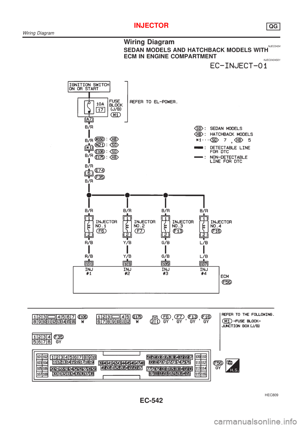
Wiring DiagramNJEC0434SEDAN MODELS AND HATCHBACK MODELS WITH
ECM IN ENGINE COMPARTMENT
NJEC0434S01
HEC809
INJECTORQG
Wiring Diagram
EC-542
Page 1267 of 2898
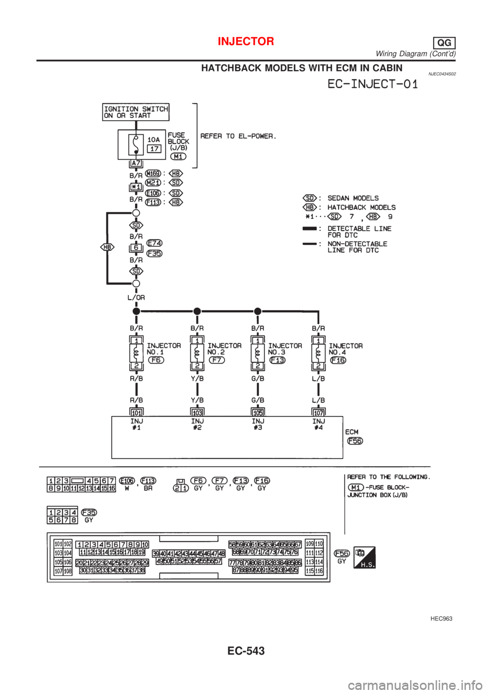
HATCHBACK MODELS WITH ECM IN CABINNJEC0434S02
HEC963
INJECTORQG
Wiring Diagram (Cont'd)
EC-543
Page 1268 of 2898
Diagnostic ProcedureNJEC0438
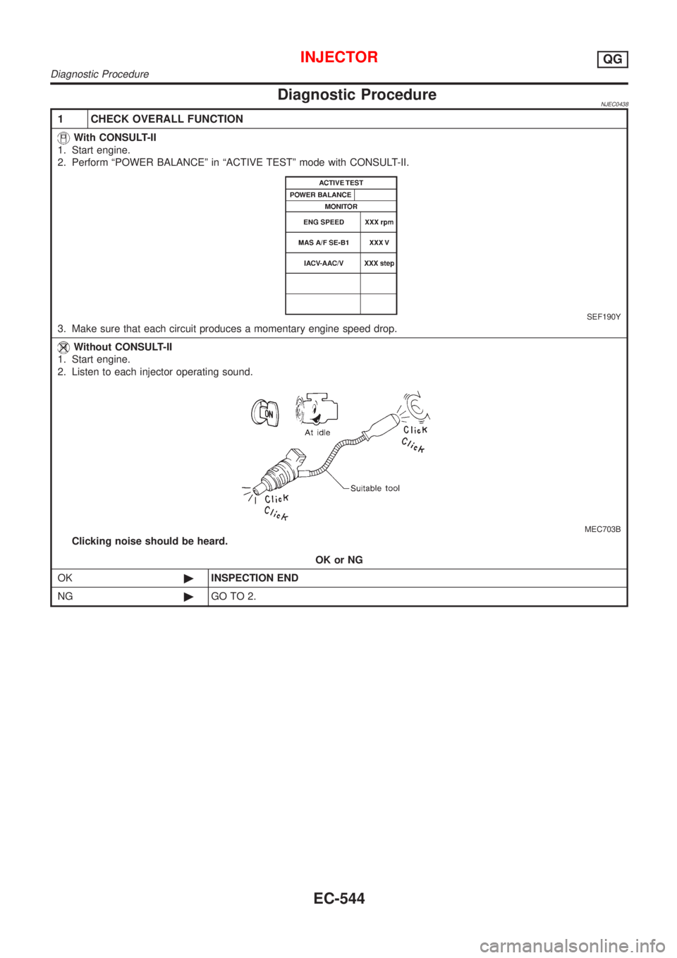
1 CHECK OVERALL FUNCTION
With CONSULT-II
1. Start engine.
2. Perform ªPOWER BALANCEº in ªACTIVE TESTº mode with CONSULT-II.
SEF190Y
3. Make sure that each circuit produces a momentary engine speed drop.
Without CONSULT-II
1. Start engine.
2. Listen to each injector operating sound.
MEC703B
Clicking noise should be heard.
OK or NG
OK©INSPECTION END
NG©GO TO 2.
INJECTORQG
Diagnostic Procedure
EC-544
Page 1269 of 2898
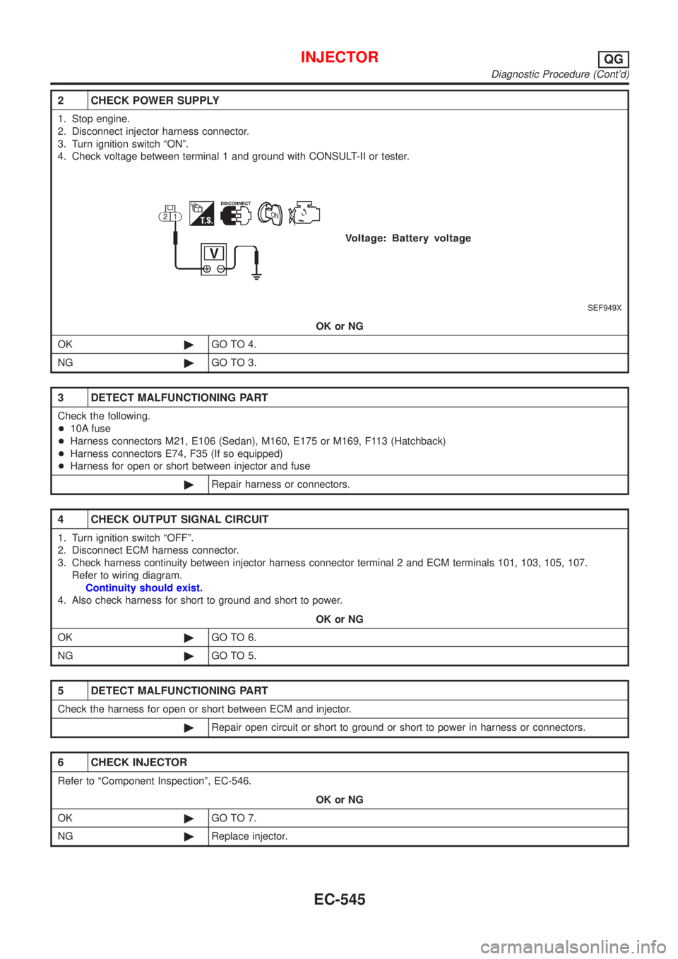
2 CHECK POWER SUPPLY
1. Stop engine.
2. Disconnect injector harness connector.
3. Turn ignition switch ªONº.
4. Check voltage between terminal 1 and ground with CONSULT-II or tester.
SEF949X
OK or NG
OK©GO TO 4.
NG©GO TO 3.
3 DETECT MALFUNCTIONING PART
Check the following.
+10A fuse
+Harness connectors M21, E106 (Sedan), M160, E175 or M169, F113 (Hatchback)
+Harness connectors E74, F35 (If so equipped)
+Harness for open or short between injector and fuse
©Repair harness or connectors.
4 CHECK OUTPUT SIGNAL CIRCUIT
1. Turn ignition switch ªOFFº.
2. Disconnect ECM harness connector.
3. Check harness continuity between injector harness connector terminal 2 and ECM terminals 101, 103, 105, 107.
Refer to wiring diagram.
Continuity should exist.
4. Also check harness for short to ground and short to power.
OK or NG
OK©GO TO 6.
NG©GO TO 5.
5 DETECT MALFUNCTIONING PART
Check the harness for open or short between ECM and injector.
©Repair open circuit or short to ground or short to power in harness or connectors.
6 CHECK INJECTOR
Refer to ªComponent Inspectionº, EC-546.
OK or NG
OK©GO TO 7.
NG©Replace injector.
INJECTORQG
Diagnostic Procedure (Cont'd)
EC-545
Page 1270 of 2898
7 CHECK INTERMITTENT INCIDENT
Perform ªTROUBLE DIAGNOSIS FOR INTERMITTENT INCIDENTº, EC-177.
©INSPECTION END
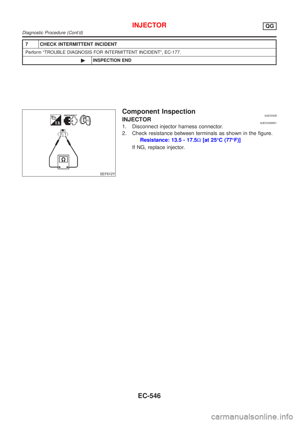
SEF612Y
Component InspectionNJEC0439INJECTORNJEC0439S011. Disconnect injector harness connector.
2. Check resistance between terminals as shown in the figure.
Resistance: 13.5 - 17.5W[at 25ÉC (77ÉF)]
If NG, replace injector.
INJECTORQG
Diagnostic Procedure (Cont'd)
EC-546
Trending: load capacity, airbag, battery capacity, oil level, boot, timing belt, headlamp
