clutch NISSAN ALMERA 2001 Service Manual
[x] Cancel search | Manufacturer: NISSAN, Model Year: 2001, Model line: ALMERA, Model: NISSAN ALMERA 2001Pages: 2898, PDF Size: 60.76 MB
Page 457 of 2898
SAT124E
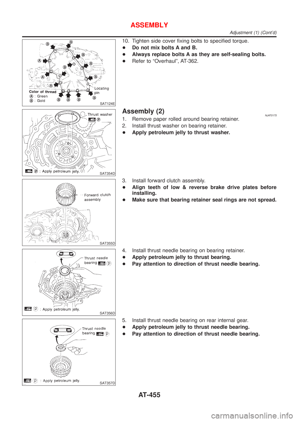
10. Tighten side cover fixing bolts to specified torque.
+Do not mix bolts A and B.
+Always replace bolts A as they are self-sealing bolts.
+Refer to ªOverhaulº, AT-362.
SAT354D
Assembly (2)NJAT01751. Remove paper rolled around bearing retainer.
2. Install thrust washer on bearing retainer.
+Apply petroleum jelly to thrust washer.
SAT355D
3. Install forward clutch assembly.
+Align teeth of low & reverse brake drive plates before
installing.
+Make sure that bearing retainer seal rings are not spread.
SAT356D
4. Install thrust needle bearing on bearing retainer.
+Apply petroleum jelly to thrust bearing.
+Pay attention to direction of thrust needle bearing.
SAT357D
5. Install thrust needle bearing on rear internal gear.
+Apply petroleum jelly to thrust needle bearing.
+Pay attention to direction of thrust needle bearing.
ASSEMBLY
Adjustment (1) (Cont'd)
AT-455
Page 458 of 2898
SAT358D
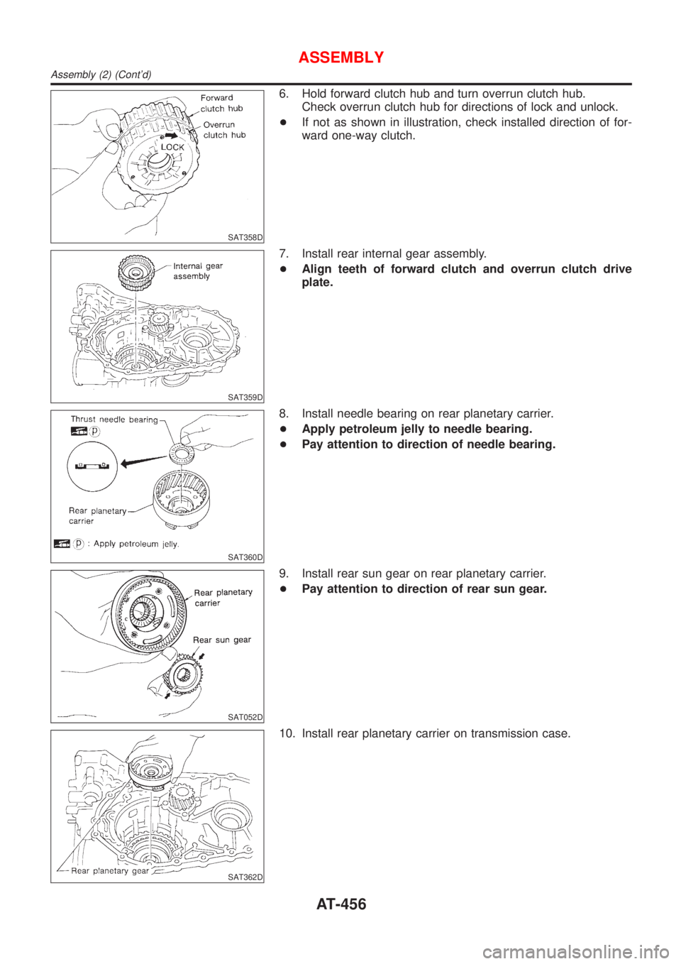
6. Hold forward clutch hub and turn overrun clutch hub.
Check overrun clutch hub for directions of lock and unlock.
+If not as shown in illustration, check installed direction of for-
ward one-way clutch.
SAT359D
7. Install rear internal gear assembly.
+Align teeth of forward clutch and overrun clutch drive
plate.
SAT360D
8. Install needle bearing on rear planetary carrier.
+Apply petroleum jelly to needle bearing.
+Pay attention to direction of needle bearing.
SAT052D
9. Install rear sun gear on rear planetary carrier.
+Pay attention to direction of rear sun gear.
SAT362D
10. Install rear planetary carrier on transmission case.
ASSEMBLY
Assembly (2) (Cont'd)
AT-456
Page 459 of 2898
SAT363D
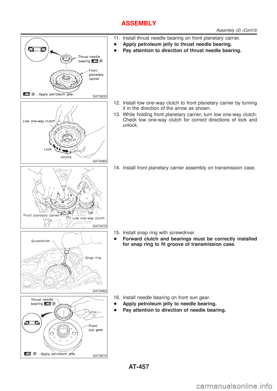
11. Install thrust needle bearing on front planetary carrier.
+Apply petroleum jelly to thrust needle bearing.
+Pay attention to direction of thrust needle bearing.
SAT048D
12. Install low one-way clutch to front planetary carrier by turning
it in the direction of the arrow as shown.
13. While holding front planetary carrier, turn low one-way clutch.
Check low one-way clutch for correct directions of lock and
unlock.
SAT047D
14. Install front planetary carrier assembly on transmission case.
SAT046D
15. Install snap ring with screwdriver.
+Forward clutch and bearings must be correctly installed
for snap ring to fit groove of transmission case.
SAT367D
16. Install needle bearing on front sun gear.
+Apply petroleum jelly to needle bearing.
+Pay attention to direction of needle bearing.
ASSEMBLY
Assembly (2) (Cont'd)
AT-457
Page 460 of 2898

SAT368D
17. Install front sun gear on front planetary carrier.
SAT369D
18. Install needle bearing on front sun gear.
+Apply petroleum jelly to needle bearing.
+Pay attention to direction of needle bearing.
SAT370D
19. Install high clutch hub on front sun gear.
SAT371D
20. Install needle bearing on high clutch hub.
+Apply petroleum jelly to needle bearing.
+Pay attention to direction of needle bearing.
SAT372D
21. Remove paper rolled around input shaft.
22. Install input shaft assembly.
+Align teeth of high clutch drive plates before installing.
ASSEMBLY
Assembly (2) (Cont'd)
AT-458
Page 461 of 2898
SAT373D
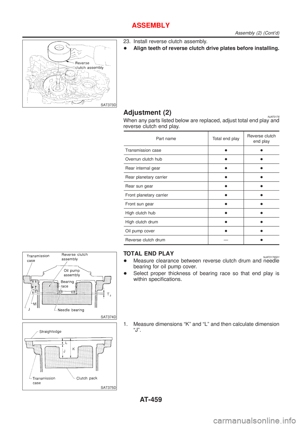
23. Install reverse clutch assembly.
+Align teeth of reverse clutch drive plates before installing.
Adjustment (2)NJAT0176When any parts listed below are replaced, adjust total end play and
reverse clutch end play.
Part name Total end playReverse clutch
end play
Transmission case++
Overrun clutch hub++
Rear internal gear++
Rear planetary carrier++
Rear sun gear++
Front planetary carrier++
Front sun gear++
High clutch hub++
High clutch drum++
Oil pump cover++
Reverse clutch drum Ð+
SAT374D
TOTAL END PLAYNJAT0176S01+Measure clearance between reverse clutch drum and needle
bearing for oil pump cover.
+Select proper thickness of bearing race so that end play is
within specifications.
SAT375D
1. Measure dimensions ªKº and ªLº and then calculate dimension
ªJº.
ASSEMBLY
Assembly (2) (Cont'd)
AT-459
Page 462 of 2898
SAT376D
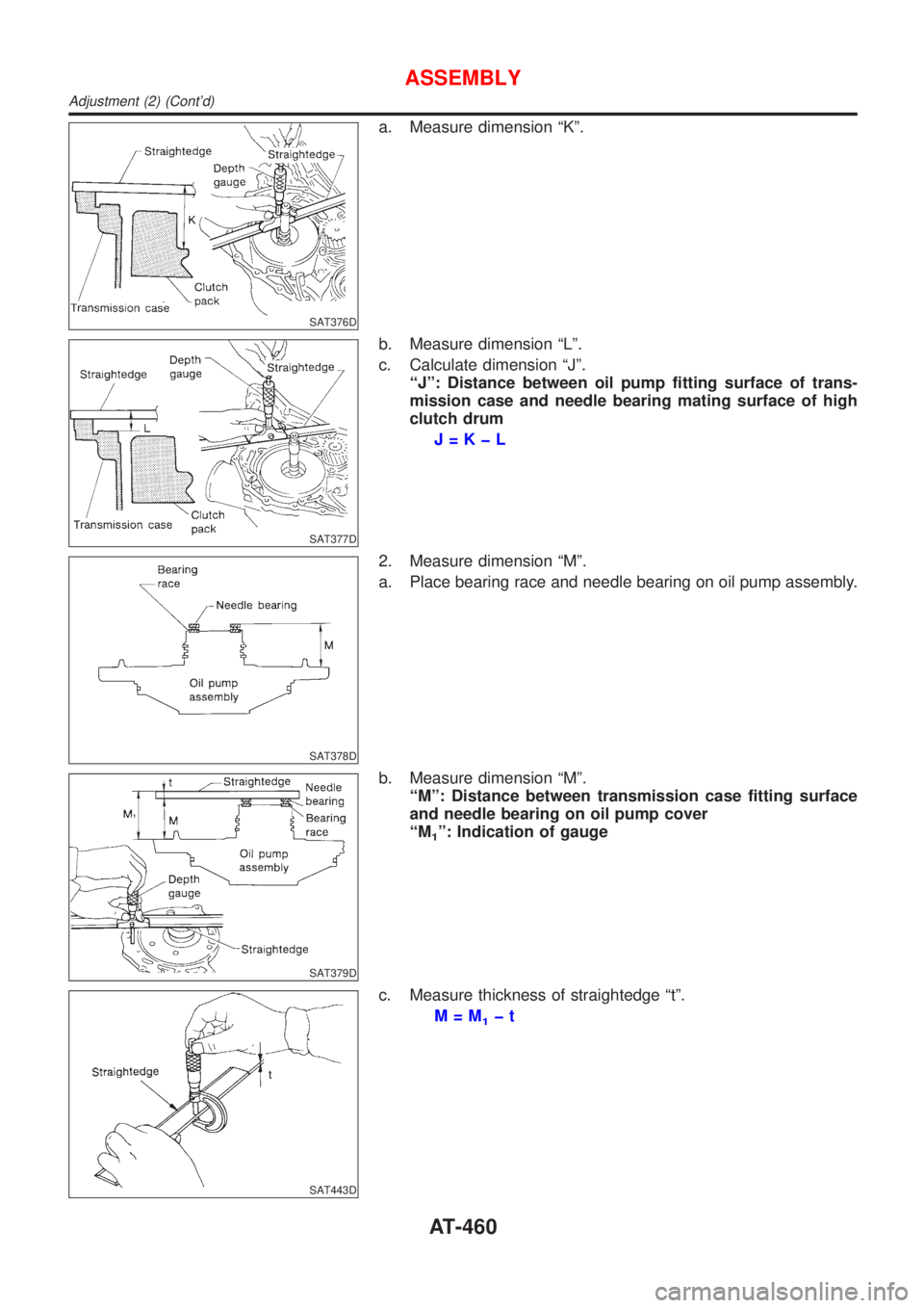
a. Measure dimension ªKº.
SAT377D
b. Measure dimension ªLº.
c. Calculate dimension ªJº.
ªJº: Distance between oil pump fitting surface of trans-
mission case and needle bearing mating surface of high
clutch drum
J=KþL
SAT378D
2. Measure dimension ªMº.
a. Place bearing race and needle bearing on oil pump assembly.
SAT379D
b. Measure dimension ªMº.
ªMº: Distance between transmission case fitting surface
and needle bearing on oil pump cover
ªM
1º: Indication of gauge
SAT443D
c. Measure thickness of straightedge ªtº.
M=M
1þt
ASSEMBLY
Adjustment (2) (Cont'd)
AT-460
Page 463 of 2898

3. Adjust total end play ªT3º.
T
3=JþM
Total end play ªT
3º:
0.25 - 0.55 mm (0.0098 - 0.0217 in)
+Select proper thickness of bearing race so that total end play
is within specifications.
Bearing races: Refer to SDS, AT-484.
SAT380D
REVERSE CLUTCH END PLAYNJAT0176S02+Measure clearance between oil pump cover and thrust washer
for reverse clutch drum.
+Select proper thickness of thrust washer so that end play is
within specifications.
SAT381D
1. Measure dimensions ªOº and ªPº and then calculate dimension
ªNº.
SAT382D
a. Place thrust washer on reverse clutch drum.
b. Measure dimension ªOº.
SAT383D
c. Measure dimension ªPº.
d. Calculate dimension ªNº.
ªNº: Distance between oil pump fitting surface of trans-
mission case and thrust washer on reverse clutch drum
N=OþP
ASSEMBLY
Adjustment (2) (Cont'd)
AT-461
Page 464 of 2898

SAT384D
2. Measure dimensions ªRº and ªSº and then calculate dimension
ªQº.
SAT385D
a. Measure dimension ªRº.
SAT386D
b. Measure dimension ªSº.
c. Calculate dimension ªQº.
ªQº: Distance between transmission case fitting surface
and thrust washer mating surface
Q=RþS
3. Adjust reverse clutch end play ªT
4º.
T
4=NþQ
Reverse clutch end play:
0.65 - 1.00 mm (0.0256 - 0.0394 in)
+Select proper thickness of thrust washer so that reverse clutch
end play is within specifications.
Thrust washer: Refer to SDS, AT-484.
SAT387D
Assembly (3)NJAT01771. Remove reverse clutch assembly and install needle bearing on
high clutch assembly.
+Pay attention to direction of needle bearing.
2. Install reverse clutch assembly.
ASSEMBLY
Adjustment (2) (Cont'd)
AT-462
Page 465 of 2898
SAT038D
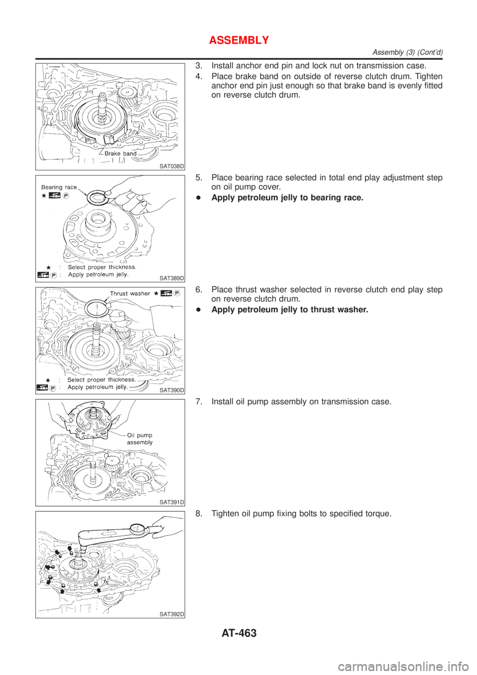
3. Install anchor end pin and lock nut on transmission case.
4. Place brake band on outside of reverse clutch drum. Tighten
anchor end pin just enough so that brake band is evenly fitted
on reverse clutch drum.
SAT389D
5. Place bearing race selected in total end play adjustment step
on oil pump cover.
+Apply petroleum jelly to bearing race.
SAT390D
6. Place thrust washer selected in reverse clutch end play step
on reverse clutch drum.
+Apply petroleum jelly to thrust washer.
SAT391D
7. Install oil pump assembly on transmission case.
SAT392D
8. Tighten oil pump fixing bolts to specified torque.
ASSEMBLY
Assembly (3) (Cont'd)
AT-463
Page 476 of 2898
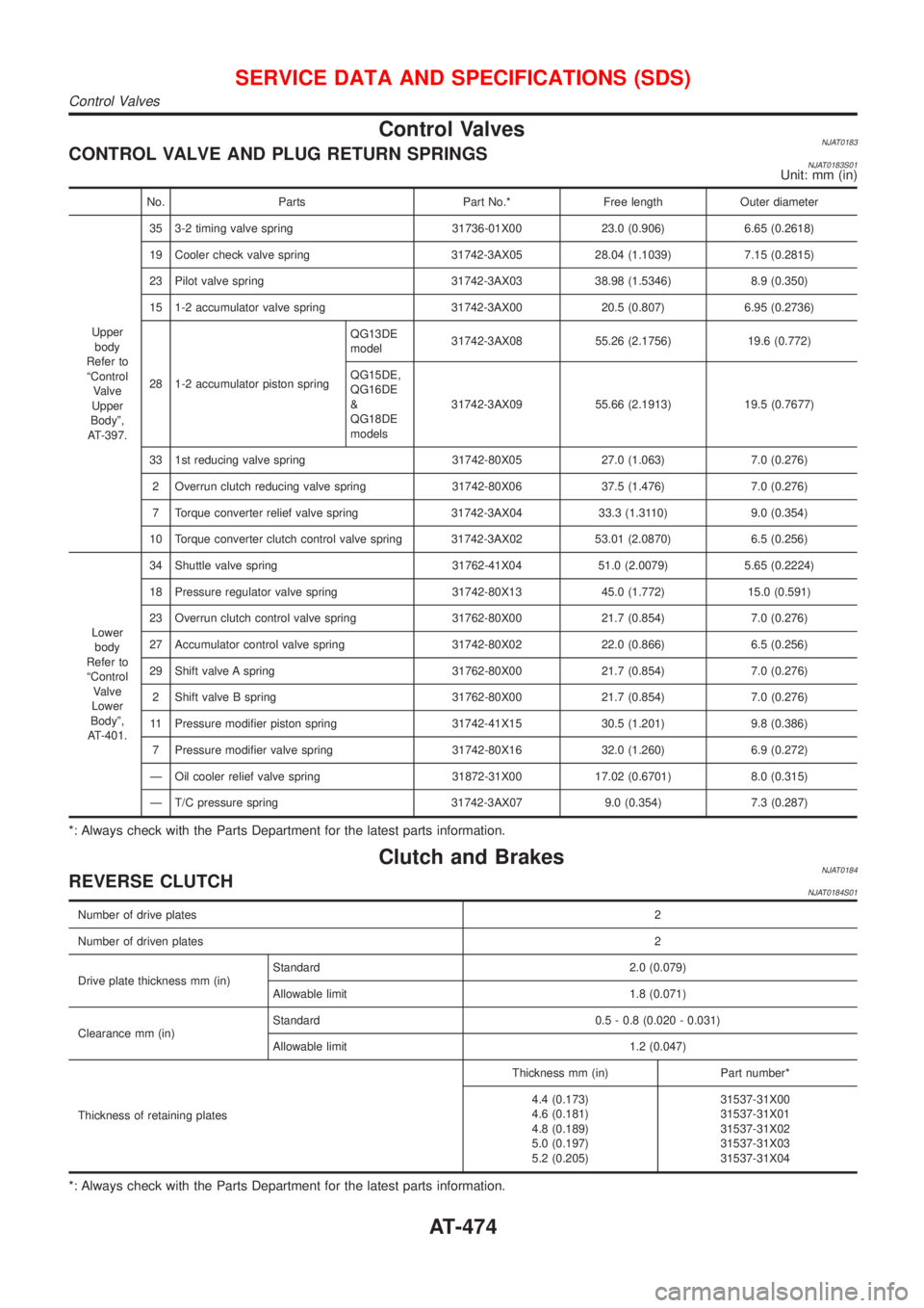
Control ValvesNJAT0183CONTROL VALVE AND PLUG RETURN SPRINGSNJAT0183S01Unit: mm (in)
No. Parts Part No.* Free length Outer diameter
Upper
body
Refer to
ªControl
Valve
Upper
Bodyº,
AT-397.35 3-2 timing valve spring 31736-01X00 23.0 (0.906) 6.65 (0.2618)
19 Cooler check valve spring 31742-3AX05 28.04 (1.1039) 7.15 (0.2815)
23 Pilot valve spring 31742-3AX03 38.98 (1.5346) 8.9 (0.350)
15 1-2 accumulator valve spring 31742-3AX00 20.5 (0.807) 6.95 (0.2736)
28 1-2 accumulator piston springQG13DE
model31742-3AX08 55.26 (2.1756) 19.6 (0.772)
QG15DE,
QG16DE
&
QG18DE
models31742-3AX09 55.66 (2.1913) 19.5 (0.7677)
33 1st reducing valve spring 31742-80X05 27.0 (1.063) 7.0 (0.276)
2 Overrun clutch reducing valve spring 31742-80X06 37.5 (1.476) 7.0 (0.276)
7 Torque converter relief valve spring 31742-3AX04 33.3 (1.3110) 9.0 (0.354)
10 Torque converter clutch control valve spring 31742-3AX02 53.01 (2.0870) 6.5 (0.256)
Lower
body
Refer to
ªControl
Valve
Lower
Bodyº,
AT-401.34 Shuttle valve spring 31762-41X04 51.0 (2.0079) 5.65 (0.2224)
18 Pressure regulator valve spring 31742-80X13 45.0 (1.772) 15.0 (0.591)
23 Overrun clutch control valve spring 31762-80X00 21.7 (0.854) 7.0 (0.276)
27 Accumulator control valve spring 31742-80X02 22.0 (0.866) 6.5 (0.256)
29 Shift valve A spring 31762-80X00 21.7 (0.854) 7.0 (0.276)
2 Shift valve B spring 31762-80X00 21.7 (0.854) 7.0 (0.276)
11 Pressure modifier piston spring 31742-41X15 30.5 (1.201) 9.8 (0.386)
7 Pressure modifier valve spring 31742-80X16 32.0 (1.260) 6.9 (0.272)
Ð Oil cooler relief valve spring 31872-31X00 17.02 (0.6701) 8.0 (0.315)
Ð T/C pressure spring 31742-3AX07 9.0 (0.354) 7.3 (0.287)
*: Always check with the Parts Department for the latest parts information.
Clutch and BrakesNJAT0184REVERSE CLUTCHNJAT0184S01
Number of drive plates2
Number of driven plates2
Drive plate thickness mm (in)Standard 2.0 (0.079)
Allowable limit 1.8 (0.071)
Clearance mm (in)Standard 0.5 - 0.8 (0.020 - 0.031)
Allowable limit 1.2 (0.047)
Thickness of retaining platesThickness mm (in) Part number*
4.4 (0.173)
4.6 (0.181)
4.8 (0.189)
5.0 (0.197)
5.2 (0.205)31537-31X00
31537-31X01
31537-31X02
31537-31X03
31537-31X04
*: Always check with the Parts Department for the latest parts information.
SERVICE DATA AND SPECIFICATIONS (SDS)
Control Valves
AT-474