clutch NISSAN ALMERA 2001 Service Manual
[x] Cancel search | Manufacturer: NISSAN, Model Year: 2001, Model line: ALMERA, Model: NISSAN ALMERA 2001Pages: 2898, PDF Size: 60.76 MB
Page 477 of 2898
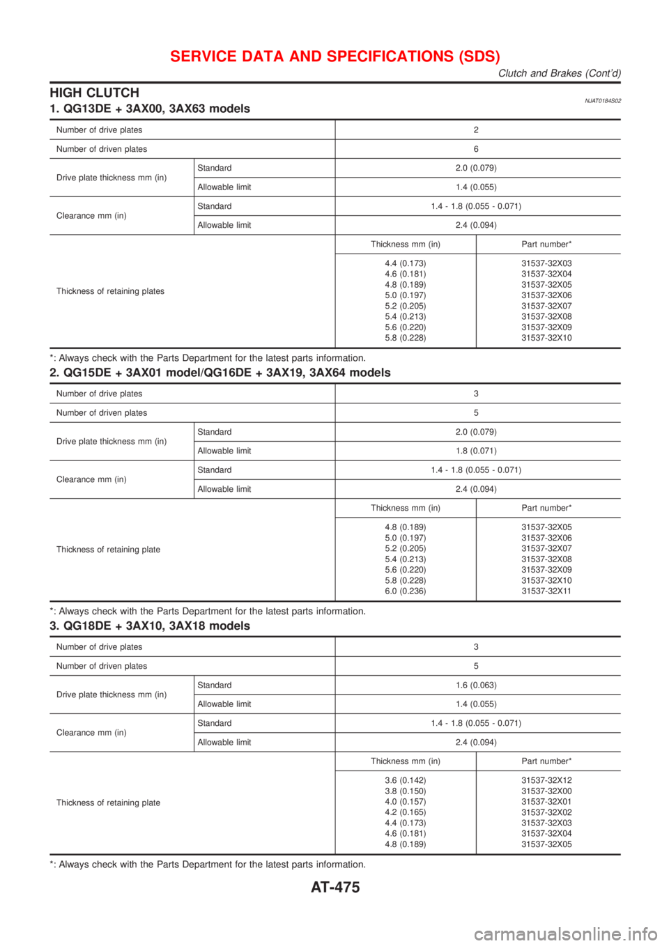
HIGH CLUTCHNJAT0184S021. QG13DE + 3AX00, 3AX63 models
Number of drive plates2
Number of driven plates6
Drive plate thickness mm (in)Standard 2.0 (0.079)
Allowable limit 1.4 (0.055)
Clearance mm (in)Standard 1.4 - 1.8 (0.055 - 0.071)
Allowable limit 2.4 (0.094)
Thickness of retaining platesThickness mm (in) Part number*
4.4 (0.173)
4.6 (0.181)
4.8 (0.189)
5.0 (0.197)
5.2 (0.205)
5.4 (0.213)
5.6 (0.220)
5.8 (0.228)31537-32X03
31537-32X04
31537-32X05
31537-32X06
31537-32X07
31537-32X08
31537-32X09
31537-32X10
*: Always check with the Parts Department for the latest parts information.
2. QG15DE + 3AX01 model/QG16DE + 3AX19, 3AX64 models
Number of drive plates3
Number of driven plates5
Drive plate thickness mm (in)Standard 2.0 (0.079)
Allowable limit 1.8 (0.071)
Clearance mm (in)Standard 1.4 - 1.8 (0.055 - 0.071)
Allowable limit 2.4 (0.094)
Thickness of retaining plateThickness mm (in) Part number*
4.8 (0.189)
5.0 (0.197)
5.2 (0.205)
5.4 (0.213)
5.6 (0.220)
5.8 (0.228)
6.0 (0.236)31537-32X05
31537-32X06
31537-32X07
31537-32X08
31537-32X09
31537-32X10
31537-32X11
*: Always check with the Parts Department for the latest parts information.
3. QG18DE + 3AX10, 3AX18 models
Number of drive plates3
Number of driven plates5
Drive plate thickness mm (in)Standard 1.6 (0.063)
Allowable limit 1.4 (0.055)
Clearance mm (in)Standard 1.4 - 1.8 (0.055 - 0.071)
Allowable limit 2.4 (0.094)
Thickness of retaining plateThickness mm (in) Part number*
3.6 (0.142)
3.8 (0.150)
4.0 (0.157)
4.2 (0.165)
4.4 (0.173)
4.6 (0.181)
4.8 (0.189)31537-32X12
31537-32X00
31537-32X01
31537-32X02
31537-32X03
31537-32X04
31537-32X05
*: Always check with the Parts Department for the latest parts information.
SERVICE DATA AND SPECIFICATIONS (SDS)
Clutch and Brakes (Cont'd)
AT-475
Page 478 of 2898
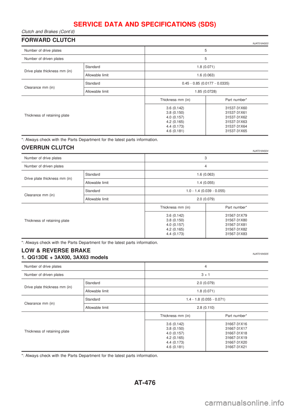
FORWARD CLUTCHNJAT0184S03
Number of drive plates5
Number of driven plates5
Drive plate thickness mm (in)Standard 1.8 (0.071)
Allowable limit 1.6 (0.063)
Clearance mm (in)Standard 0.45 - 0.85 (0.0177 - 0.0335)
Allowable limit 1.85 (0.0728)
Thickness of retaining plateThickness mm (in) Part number*
3.6 (0.142)
3.8 (0.150)
4.0 (0.157)
4.2 (0.165)
4.4 (0.173)
4.6 (0.181)31537-31X60
31537-31X61
31537-31X62
31537-31X63
31537-31X64
31537-31X65
*: Always check with the Parts Department for the latest parts information.
OVERRUN CLUTCHNJAT0184S04
Number of drive plates3
Number of driven plates4
Drive plate thickness mm (in)Standard 1.6 (0.063)
Allowable limit 1.4 (0.055)
Clearance mm (in)Standard 1.0 - 1.4 (0.039 - 0.055)
Allowable limit 2.0 (0.079)
Thickness of retaining plateThickness mm (in) Part number*
3.6 (0.142)
3.8 (0.150)
4.0 (0.157)
4.2 (0.165)
4.4 (0.173)31567-31X79
31567-31X80
31567-31X81
31567-31X82
31567-31X83
*: Always check with the Parts Department for the latest parts information.
LOW & REVERSE BRAKENJAT0184S051. QG13DE + 3AX00, 3AX63 models
Number of drive plates4
Number of driven plates3+1
Drive plate thickness mm (in)Standard 2.0 (0.079)
Allowable limit 1.8 (0.071)
Clearance mm (in)Standard 1.4 - 1.8 (0.055 - 0.071)
Allowable limit 2.8 (0.110)
Thickness of retaining plateThickness mm (in) Part number*
3.6 (0.142)
3.8 (0.150)
4.0 (0.157)
4.2 (0.165)
4.4 (0.173)
4.6 (0.181)31667-31X16
31667-31X17
31667-31X18
31667-31X19
31667-31X20
31667-31X21
*: Always check with the Parts Department for the latest parts information.
SERVICE DATA AND SPECIFICATIONS (SDS)
Clutch and Brakes (Cont'd)
AT-476
Page 479 of 2898
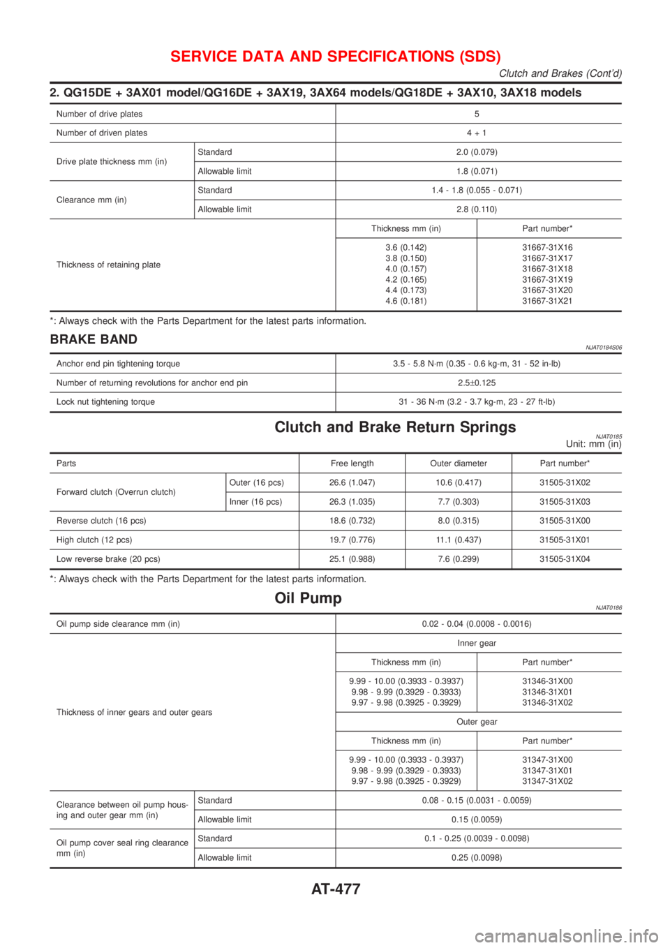
2. QG15DE + 3AX01 model/QG16DE + 3AX19, 3AX64 models/QG18DE + 3AX10, 3AX18 models
Number of drive plates5
Number of driven plates4+1
Drive plate thickness mm (in)Standard 2.0 (0.079)
Allowable limit 1.8 (0.071)
Clearance mm (in)Standard 1.4 - 1.8 (0.055 - 0.071)
Allowable limit 2.8 (0.110)
Thickness of retaining plateThickness mm (in) Part number*
3.6 (0.142)
3.8 (0.150)
4.0 (0.157)
4.2 (0.165)
4.4 (0.173)
4.6 (0.181)31667-31X16
31667-31X17
31667-31X18
31667-31X19
31667-31X20
31667-31X21
*: Always check with the Parts Department for the latest parts information.
BRAKE BANDNJAT0184S06
Anchor end pin tightening torque 3.5 - 5.8 N´m (0.35 - 0.6 kg-m, 31 - 52 in-lb)
Number of returning revolutions for anchor end pin 2.5±0.125
Lock nut tightening torque 31 - 36 N´m (3.2 - 3.7 kg-m, 23 - 27 ft-lb)
Clutch and Brake Return SpringsNJAT0185Unit: mm (in)
Parts Free length Outer diameter Part number*
Forward clutch (Overrun clutch)Outer (16 pcs) 26.6 (1.047) 10.6 (0.417) 31505-31X02
Inner (16 pcs) 26.3 (1.035) 7.7 (0.303) 31505-31X03
Reverse clutch (16 pcs) 18.6 (0.732) 8.0 (0.315) 31505-31X00
High clutch (12 pcs) 19.7 (0.776) 11.1 (0.437) 31505-31X01
Low reverse brake (20 pcs) 25.1 (0.988) 7.6 (0.299) 31505-31X04
*: Always check with the Parts Department for the latest parts information.
Oil PumpNJAT0186
Oil pump side clearance mm (in) 0.02 - 0.04 (0.0008 - 0.0016)
Thickness of inner gears and outer gearsInner gear
Thickness mm (in) Part number*
9.99 - 10.00 (0.3933 - 0.3937)
9.98 - 9.99 (0.3929 - 0.3933)
9.97 - 9.98 (0.3925 - 0.3929)31346-31X00
31346-31X01
31346-31X02
Outer gear
Thickness mm (in) Part number*
9.99 - 10.00 (0.3933 - 0.3937)
9.98 - 9.99 (0.3929 - 0.3933)
9.97 - 9.98 (0.3925 - 0.3929)31347-31X00
31347-31X01
31347-31X02
Clearance between oil pump hous-
ing and outer gear mm (in)Standard 0.08 - 0.15 (0.0031 - 0.0059)
Allowable limit 0.15 (0.0059)
Oil pump cover seal ring clearance
mm (in)Standard 0.1 - 0.25 (0.0039 - 0.0098)
Allowable limit 0.25 (0.0098)
SERVICE DATA AND SPECIFICATIONS (SDS)
Clutch and Brakes (Cont'd)
AT-477
Page 486 of 2898
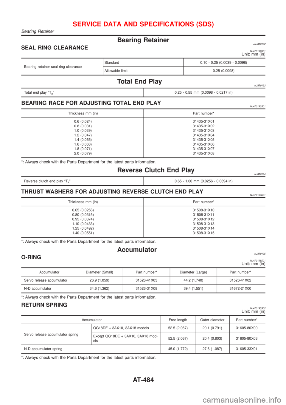
Bearing Retainer=NJAT0192SEAL RING CLEARANCENJAT0192S01Unit: mm (in)
Bearing retainer seal ring clearanceStandard 0.10 - 0.25 (0.0039 - 0.0098)
Allowable limit 0.25 (0.0098)
Total End PlayNJAT0193
Total end play ªT3º0.25 - 0.55 mm (0.0098 - 0.0217 in)
BEARING RACE FOR ADJUSTING TOTAL END PLAYNJAT0193S01
Thickness mm (in) Part number*
0.6 (0.024)
0.8 (0.031)
1.0 (0.039)
1.2 (0.047)
1.4 (0.055)
1.6 (0.063)
1.8 (0.071)
2.0 (0.079)31435-31X01
31435-31X02
31435-31X03
31435-31X04
31435-31X05
31435-31X06
31435-31X07
31435-31X08
*: Always check with the Parts Department for the latest parts information.
Reverse Clutch End PlayNJAT0194
Reverse clutch end play ªT4º 0.65 - 1.00 mm (0.0256 - 0.0394 in)
THRUST WASHERS FOR ADJUSTING REVERSE CLUTCH END PLAYNJAT0194S01
Thickness mm (in) Part number*
0.65 (0.0256)
0.80 (0.0315)
0.95 (0.0374)
1.10 (0.0433)
1.25 (0.0492)
1.40 (0.0551)31508-31X10
31508-31X11
31508-31X12
31508-31X13
31508-31X14
31508-31X15
*: Always check with the Parts Department for the latest parts information.
AccumulatorNJAT0195O-RINGNJAT0195S01Unit: mm (in)
Accumulator Diameter (Small) Part number* Diameter (Large) Part number*
Servo release accumulator 26.9 (1.059) 31526-41X03 44.2 (1.740) 31526-41X02
N-D accumulator 34.6 (1.362) 31526-31X08 39.4 (1.551) 31672-21X00
*: Always check with the Parts Department for the latest parts information.
RETURN SPRINGNJAT0195S02Unit: mm (in)
Accumulator Free length Outer diameter Part number*
Servo release accumulator springQG18DE + 3AX10, 3AX18 models 52.5 (2.067) 20.1 (0.791) 31605-80X00
Except QG18DE + 3AX10, 3AX18 mod-
els52.5 (2.067) 20.4 (0.803) 31605-80X03
N-D accumulator spring 45.0 (1.772) 27.6 (1.087) 31605-33X01
*: Always check with the Parts Department for the latest parts information.
SERVICE DATA AND SPECIFICATIONS (SDS)
Bearing Retainer
AT-484
Page 487 of 2898
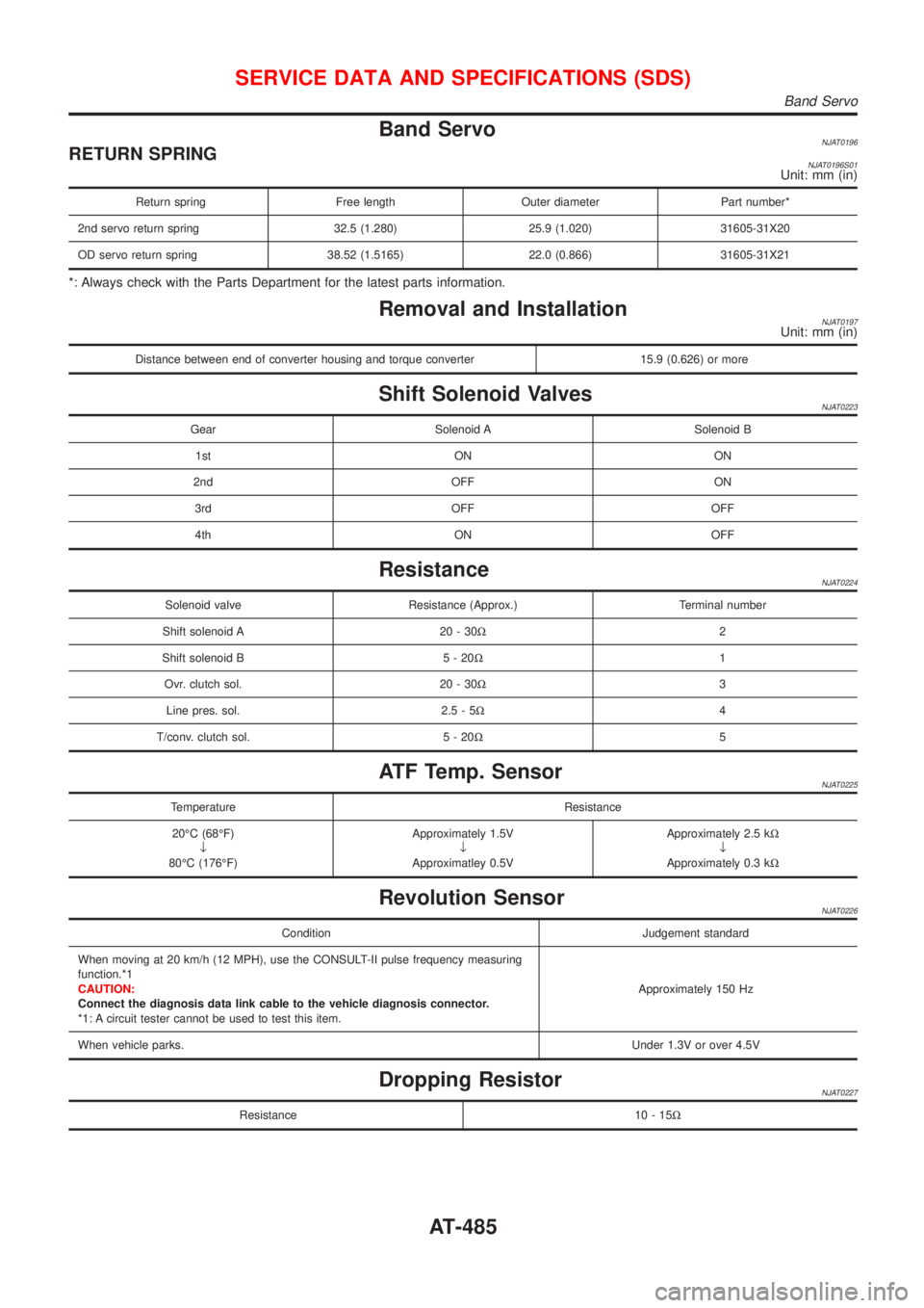
Band ServoNJAT0196RETURN SPRINGNJAT0196S01Unit: mm (in)
Return spring Free length Outer diameter Part number*
2nd servo return spring 32.5 (1.280) 25.9 (1.020) 31605-31X20
OD servo return spring 38.52 (1.5165) 22.0 (0.866) 31605-31X21
*: Always check with the Parts Department for the latest parts information.
Removal and InstallationNJAT0197Unit: mm (in)
Distance between end of converter housing and torque converter 15.9 (0.626) or more
Shift Solenoid ValvesNJAT0223
Gear Solenoid A Solenoid B
1st ON ON
2nd OFF ON
3rd OFF OFF
4th ON OFF
ResistanceNJAT0224
Solenoid valve Resistance (Approx.) Terminal number
Shift solenoid A 20 - 30W2
Shift solenoid B 5 - 20W1
Ovr. clutch sol. 20 - 30W3
Line pres. sol. 2.5 - 5W4
T/conv. clutch sol. 5 - 20W5
ATF Temp. SensorNJAT0225
Temperature Resistance
20ÉC (68ÉF)
¯
80ÉC (176ÉF)Approximately 1.5V
¯
Approximatley 0.5VApproximately 2.5 kW
¯
Approximately 0.3 kW
Revolution SensorNJAT0226
Condition Judgement standard
When moving at 20 km/h (12 MPH), use the CONSULT-II pulse frequency measuring
function.*1
CAUTION:
Connect the diagnosis data link cable to the vehicle diagnosis connector.
*1: A circuit tester cannot be used to test this item.Approximately 150 Hz
When vehicle parks.Under 1.3V or over 4.5V
Dropping ResistorNJAT0227
Resistance 10 - 15W
SERVICE DATA AND SPECIFICATIONS (SDS)
Band Servo
AT-485
Page 608 of 2898
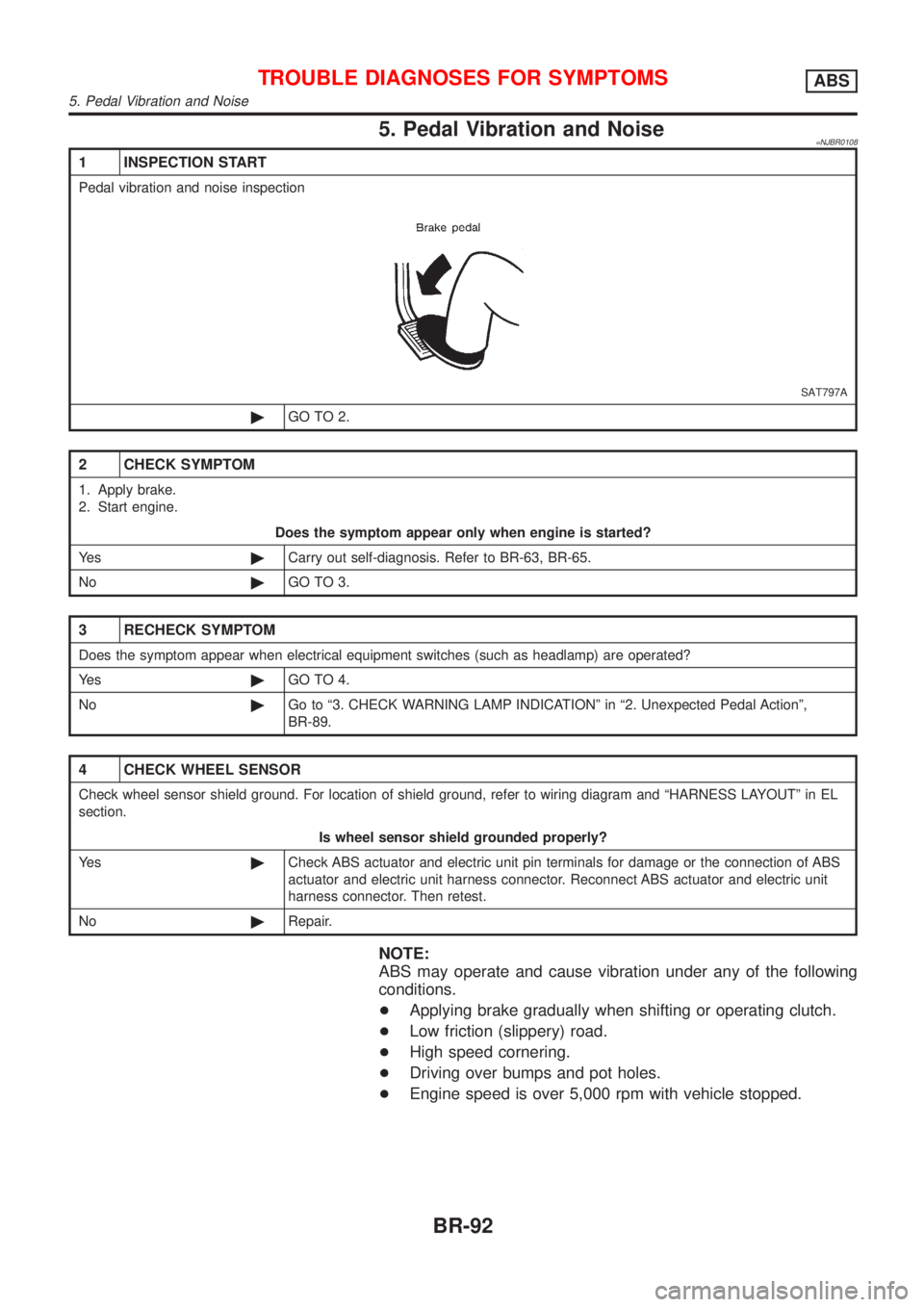
5. Pedal Vibration and Noise=NJBR0108
1 INSPECTION START
Pedal vibration and noise inspection
SAT797A
©GO TO 2.
2 CHECK SYMPTOM
1. Apply brake.
2. Start engine.
Does the symptom appear only when engine is started?
Ye s©Carry out self-diagnosis. Refer to BR-63, BR-65.
No©GO TO 3.
3 RECHECK SYMPTOM
Does the symptom appear when electrical equipment switches (such as headlamp) are operated?
Ye s©GO TO 4.
No©Go to ª3. CHECK WARNING LAMP INDICATIONº in ª2. Unexpected Pedal Actionº,
BR-89.
4 CHECK WHEEL SENSOR
Check wheel sensor shield ground. For location of shield ground, refer to wiring diagram and ªHARNESS LAYOUTº in EL
section.
Is wheel sensor shield grounded properly?
Ye s©Check ABS actuator and electric unit pin terminals for damage or the connection of ABS
actuator and electric unit harness connector. Reconnect ABS actuator and electric unit
harness connector. Then retest.
No©Repair.
NOTE:
ABS may operate and cause vibration under any of the following
conditions.
+Applying brake gradually when shifting or operating clutch.
+Low friction (slippery) road.
+High speed cornering.
+Driving over bumps and pot holes.
+Engine speed is over 5,000 rpm with vehicle stopped.
TROUBLE DIAGNOSES FOR SYMPTOMSABS
5. Pedal Vibration and Noise
BR-92
Page 701 of 2898
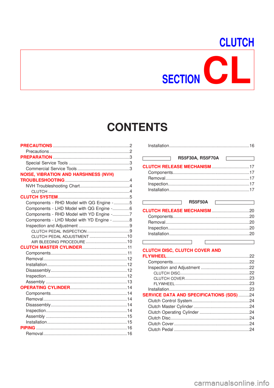
CLUTCH
SECTION
CL
CONTENTS
PRECAUTIONS...............................................................2
Precautions ..................................................................2
PREPARATION...............................................................3
Special Service Tools ..................................................3
Commercial Service Tools ...........................................3
NOISE, VIBRATION AND HARSHNESS (NVH)
TROUBLESHOOTING.....................................................4
NVH Troubleshooting Chart.........................................4
CLUTCH...................................................................4
CLUTCH SYSTEM...........................................................5
Components - RHD Model with QG Engine - .............5
Components - LHD Model with QG Engine -..............6
Components - RHD Model with YD Engine -..............7
Components - LHD Model with YD Engine - ..............8
Inspection and Adjustment ..........................................9
CLUTCH PEDAL INSPECTION...................................9
CLUTCH PEDAL ADJUSTMENT...............................10
AIR BLEEDING PROCEDURE..................................10
CLUTCH MASTER CYLINDER..................................... 11
Components............................................................... 11
Removal .....................................................................12
Installation ..................................................................12
Disassembly...............................................................12
Inspection...................................................................12
Assembly ...................................................................13
OPERATING CYLINDER...............................................14
Components...............................................................14
Removal .....................................................................14
Disassembly...............................................................14
Inspection...................................................................14
Assembly ...................................................................15
Installation ..................................................................15
PIPING...........................................................................16
Removal .....................................................................16Installation ..................................................................16
RS5F30A, RS5F70A
CLUTCH RELEASE MECHANISM...............................17
Components...............................................................17
Removal .....................................................................17
Inspection...................................................................17
Installation ..................................................................17
RS5F50A
CLUTCH RELEASE MECHANISM...............................20
Components...............................................................20
Removal .....................................................................20
Inspection...................................................................20
Installation ..................................................................20
CLUTCH DISC, CLUTCH COVER AND
FLYWHEEL....................................................................22
Components...............................................................22
Inspection and Adjustment ........................................22
CLUTCH DISC.........................................................22
CLUTCH COVER.....................................................23
FLYWHEEL.............................................................23
Installation ..................................................................23
SERVICE DATA AND SPECIFICATIONS (SDS).........24
Clutch Control System ...............................................24
Clutch Master Cylinder ..............................................24
Clutch Operating Cylinder .........................................24
Clutch Disc.................................................................24
Clutch Cover ..............................................................24
Clutch Pedal ..............................................................24
Page 702 of 2898
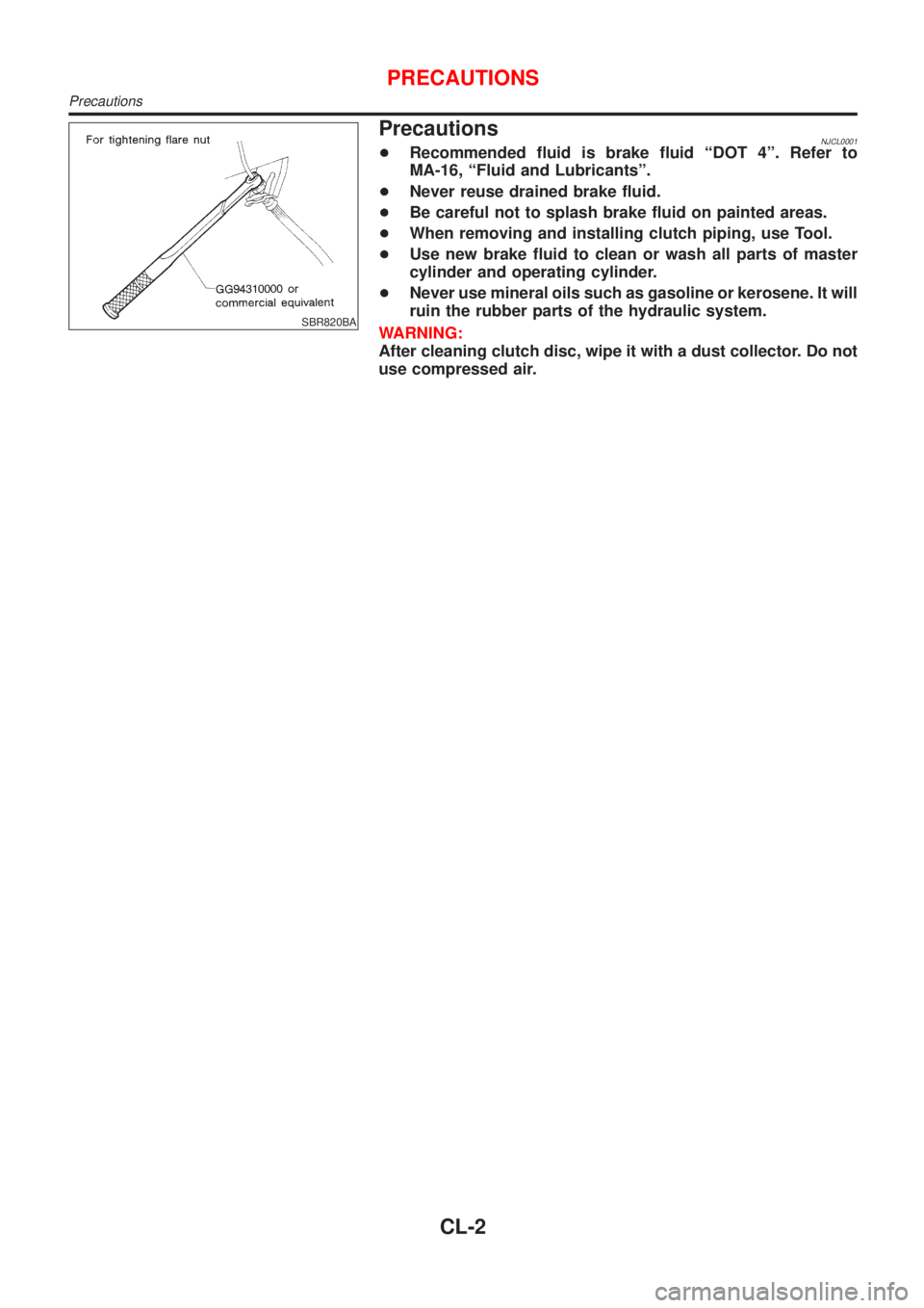
SBR820BA
PrecautionsNJCL0001+Recommended fluid is brake fluid ªDOT 4º. Refer to
MA-16, ªFluid and Lubricantsº.
+Never reuse drained brake fluid.
+Be careful not to splash brake fluid on painted areas.
+When removing and installing clutch piping, use Tool.
+Use new brake fluid to clean or wash all parts of master
cylinder and operating cylinder.
+Never use mineral oils such as gasoline or kerosene. It will
ruin the rubber parts of the hydraulic system.
WARNING:
After cleaning clutch disc, wipe it with a dust collector. Do not
use compressed air.
PRECAUTIONS
Precautions
CL-2
Page 703 of 2898
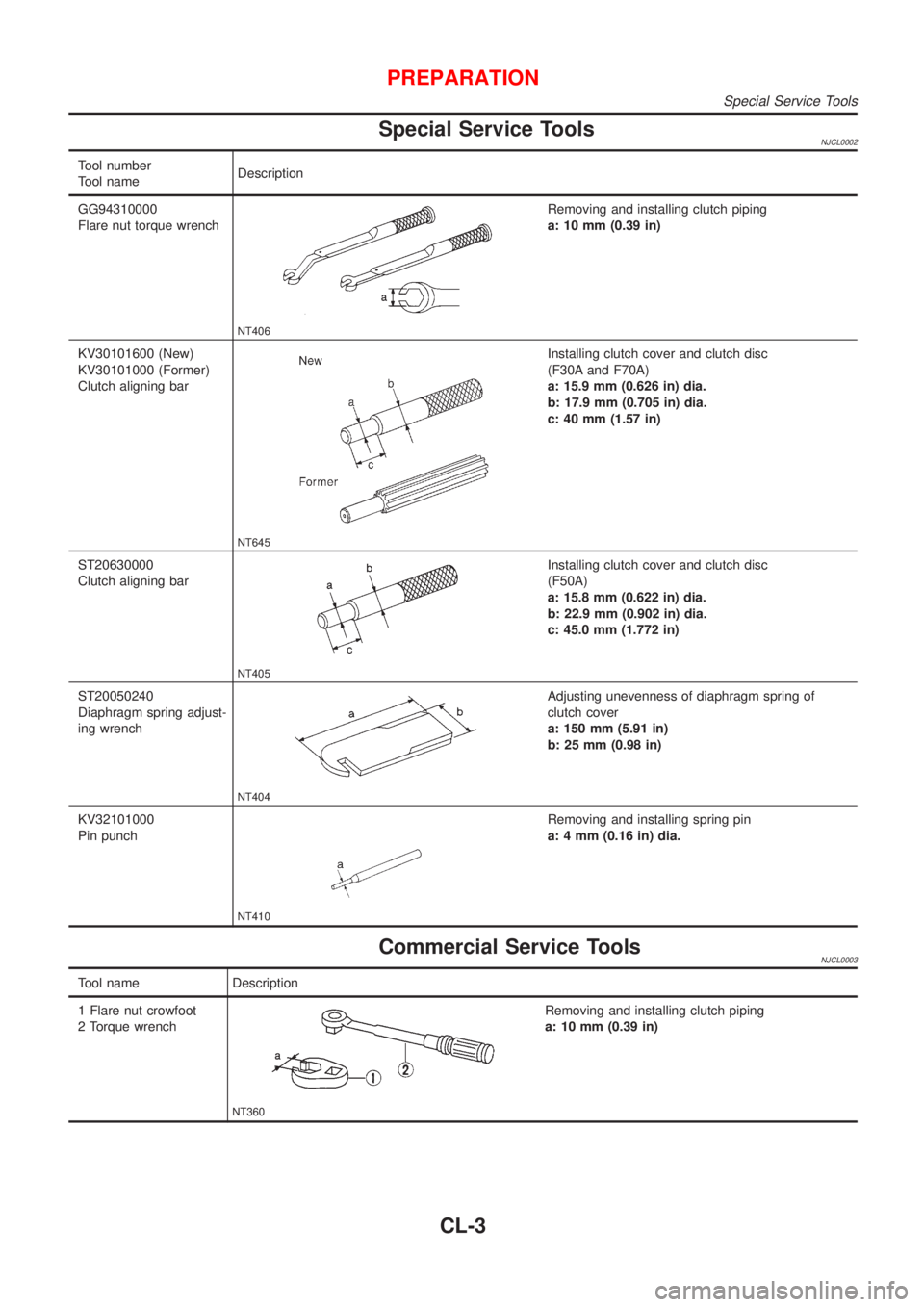
Special Service ToolsNJCL0002
Tool number
Tool nameDescription
GG94310000
Flare nut torque wrench
NT406
Removing and installing clutch piping
a: 10 mm (0.39 in)
KV30101600 (New)
KV30101000 (Former)
Clutch aligning bar
NT645
Installing clutch cover and clutch disc
(F30A and F70A)
a: 15.9 mm (0.626 in) dia.
b: 17.9 mm (0.705 in) dia.
c: 40 mm (1.57 in)
ST20630000
Clutch aligning bar
NT405
Installing clutch cover and clutch disc
(F50A)
a: 15.8 mm (0.622 in) dia.
b: 22.9 mm (0.902 in) dia.
c: 45.0 mm (1.772 in)
ST20050240
Diaphragm spring adjust-
ing wrench
NT404
Adjusting unevenness of diaphragm spring of
clutch cover
a: 150 mm (5.91 in)
b: 25 mm (0.98 in)
KV32101000
Pin punch
NT410
Removing and installing spring pin
a: 4 mm (0.16 in) dia.
Commercial Service ToolsNJCL0003
Tool name Description
1 Flare nut crowfoot
2 Torque wrench
NT360
Removing and installing clutch piping
a: 10 mm (0.39 in)
PREPARATION
Special Service Tools
CL-3
Page 704 of 2898
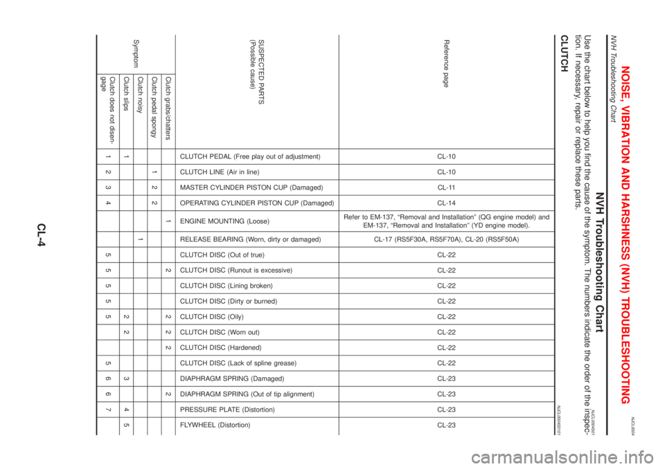
NJCL0004
NVH Troubleshooting ChartNJCL0004S01Use the chart below to help you find the cause of the symptom. The numbers indicate the order of the inspec-
tion. If necessary, repair or replace these parts.
CLUTCHNJCL0004S0101
Reference pageCL-10
CL-10
CL-11
CL-14
Refer to EM-137, ªRemoval and Installationº (QG engine model) and
EM-137, ªRemoval and Installationº (YD engine model).
CL-17 (RS5F30A, RS5F70A), CL-20 (RS5F50A)
CL-22
CL-22
CL-22
CL-22
CL-22
CL-22
CL-22
CL-22
CL-23
CL-23
CL-23
CL-23
SUSPECTED PARTS
(Possible cause)
CLUTCH PEDAL (Free play out of adjustment)
CLUTCH LINE (Air in line)
MASTER CYLINDER PISTON CUP (Damaged)
OPERATING CYLINDER PISTON CUP (Damaged)
ENGINE MOUNTING (Loose)
RELEASE BEARING (Worn, dirty or damaged)
CLUTCH DISC (Out of true)
CLUTCH DISC (Runout is excessive)
CLUTCH DISC (Lining broken)
CLUTCH DISC (Dirty or burned)
CLUTCH DISC (Oily)
CLUTCH DISC (Worn out)
CLUTCH DISC (Hardened)
CLUTCH DISC (Lack of spline grease)
DIAPHRAGM SPRING (Damaged)
DIAPHRAGM SPRING (Out of tip alignment)
PRESSURE PLATE (Distortion)
FLYWHEEL (Distortion)
SymptomClutch grabs/chatters 1 2 2 2 2 2
Clutch pedal spongy 1 2 2
Clutch noisy 1
Clutch slips 1 2 2 3 4 5
Clutch does not disen-
gage1234 55555 5667
NOISE, VIBRATION AND HARSHNESS (NVH) TROUBLESHOOTING
NVH Troubleshooting Chart
CL-4