clutch NISSAN ALMERA 2001 Service Manual
[x] Cancel search | Manufacturer: NISSAN, Model Year: 2001, Model line: ALMERA, Model: NISSAN ALMERA 2001Pages: 2898, PDF Size: 60.76 MB
Page 374 of 2898
SAT037DA
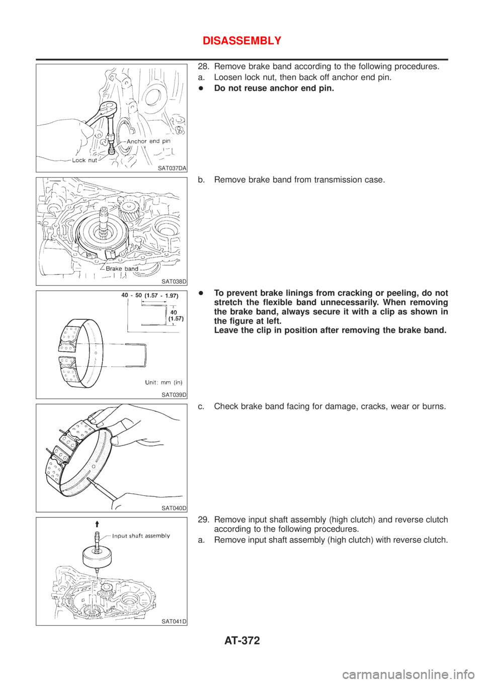
28. Remove brake band according to the following procedures.
a. Loosen lock nut, then back off anchor end pin.
+Do not reuse anchor end pin.
SAT038D
b. Remove brake band from transmission case.
SAT039D
+To prevent brake linings from cracking or peeling, do not
stretch the flexible band unnecessarily. When removing
the brake band, always secure it with a clip as shown in
the figure at left.
Leave the clip in position after removing the brake band.
SAT040D
c. Check brake band facing for damage, cracks, wear or burns.
SAT041D
29. Remove input shaft assembly (high clutch) and reverse clutch
according to the following procedures.
a. Remove input shaft assembly (high clutch) with reverse clutch.
DISASSEMBLY
AT-372
Page 375 of 2898
SAT042D
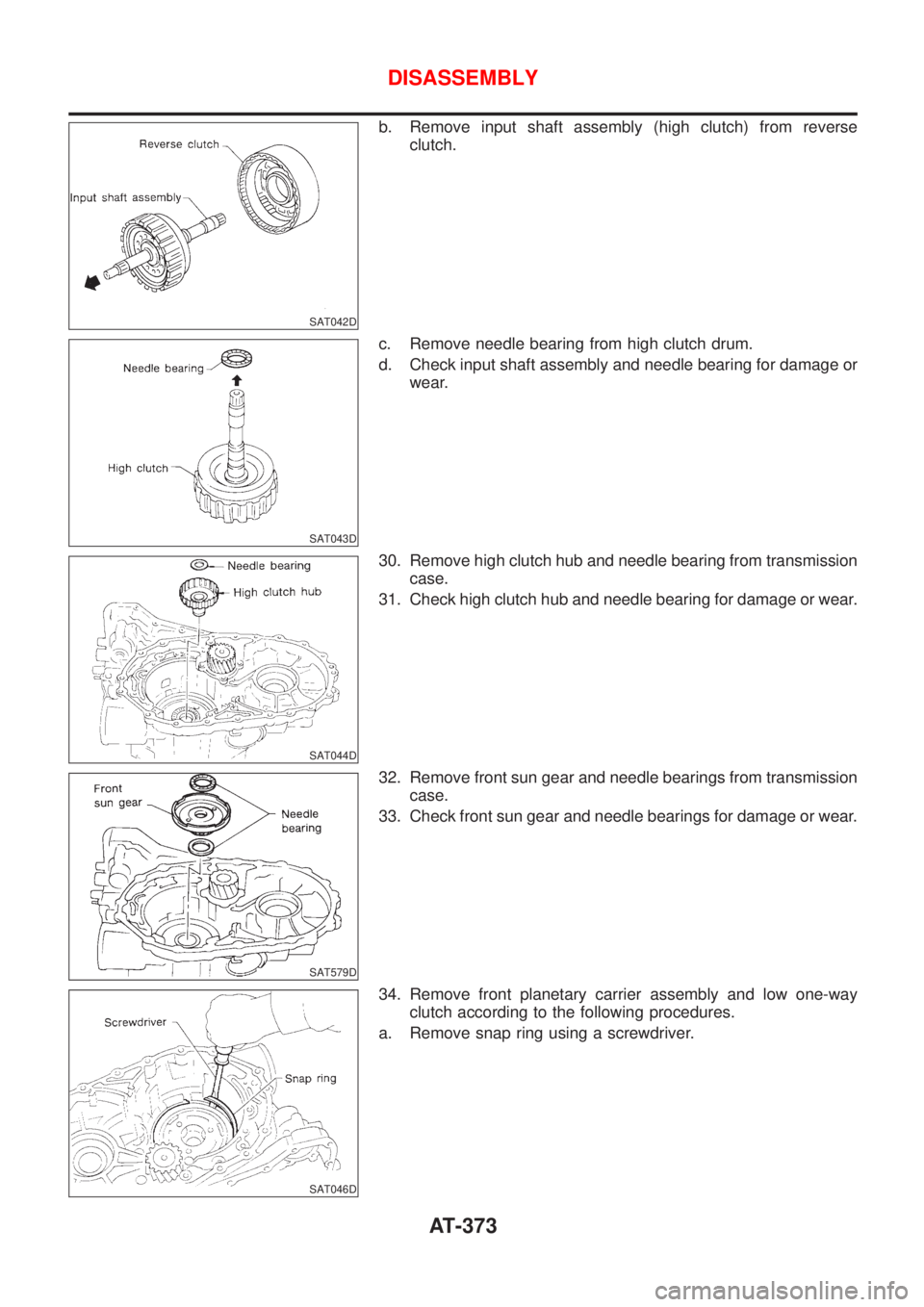
b. Remove input shaft assembly (high clutch) from reverse
clutch.
SAT043D
c. Remove needle bearing from high clutch drum.
d. Check input shaft assembly and needle bearing for damage or
wear.
SAT044D
30. Remove high clutch hub and needle bearing from transmission
case.
31. Check high clutch hub and needle bearing for damage or wear.
SAT579D
32. Remove front sun gear and needle bearings from transmission
case.
33. Check front sun gear and needle bearings for damage or wear.
SAT046D
34. Remove front planetary carrier assembly and low one-way
clutch according to the following procedures.
a. Remove snap ring using a screwdriver.
DISASSEMBLY
AT-373
Page 376 of 2898
SAT047D
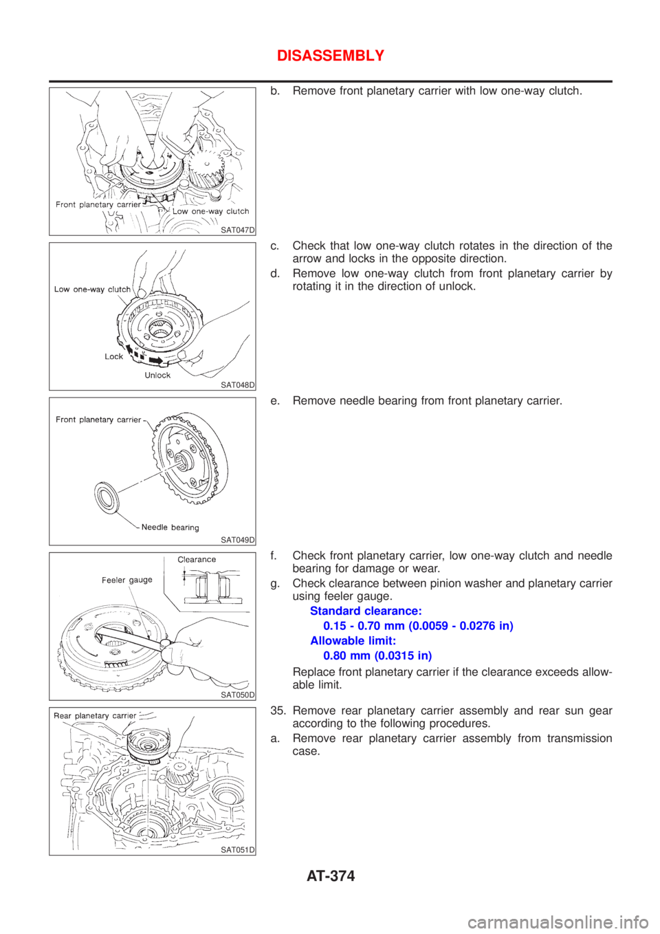
b. Remove front planetary carrier with low one-way clutch.
SAT048D
c. Check that low one-way clutch rotates in the direction of the
arrow and locks in the opposite direction.
d. Remove low one-way clutch from front planetary carrier by
rotating it in the direction of unlock.
SAT049D
e. Remove needle bearing from front planetary carrier.
SAT050D
f. Check front planetary carrier, low one-way clutch and needle
bearing for damage or wear.
g. Check clearance between pinion washer and planetary carrier
using feeler gauge.
Standard clearance:
0.15 - 0.70 mm (0.0059 - 0.0276 in)
Allowable limit:
0.80 mm (0.0315 in)
Replace front planetary carrier if the clearance exceeds allow-
able limit.
SAT051D
35. Remove rear planetary carrier assembly and rear sun gear
according to the following procedures.
a. Remove rear planetary carrier assembly from transmission
case.
DISASSEMBLY
AT-374
Page 378 of 2898
SAT272E
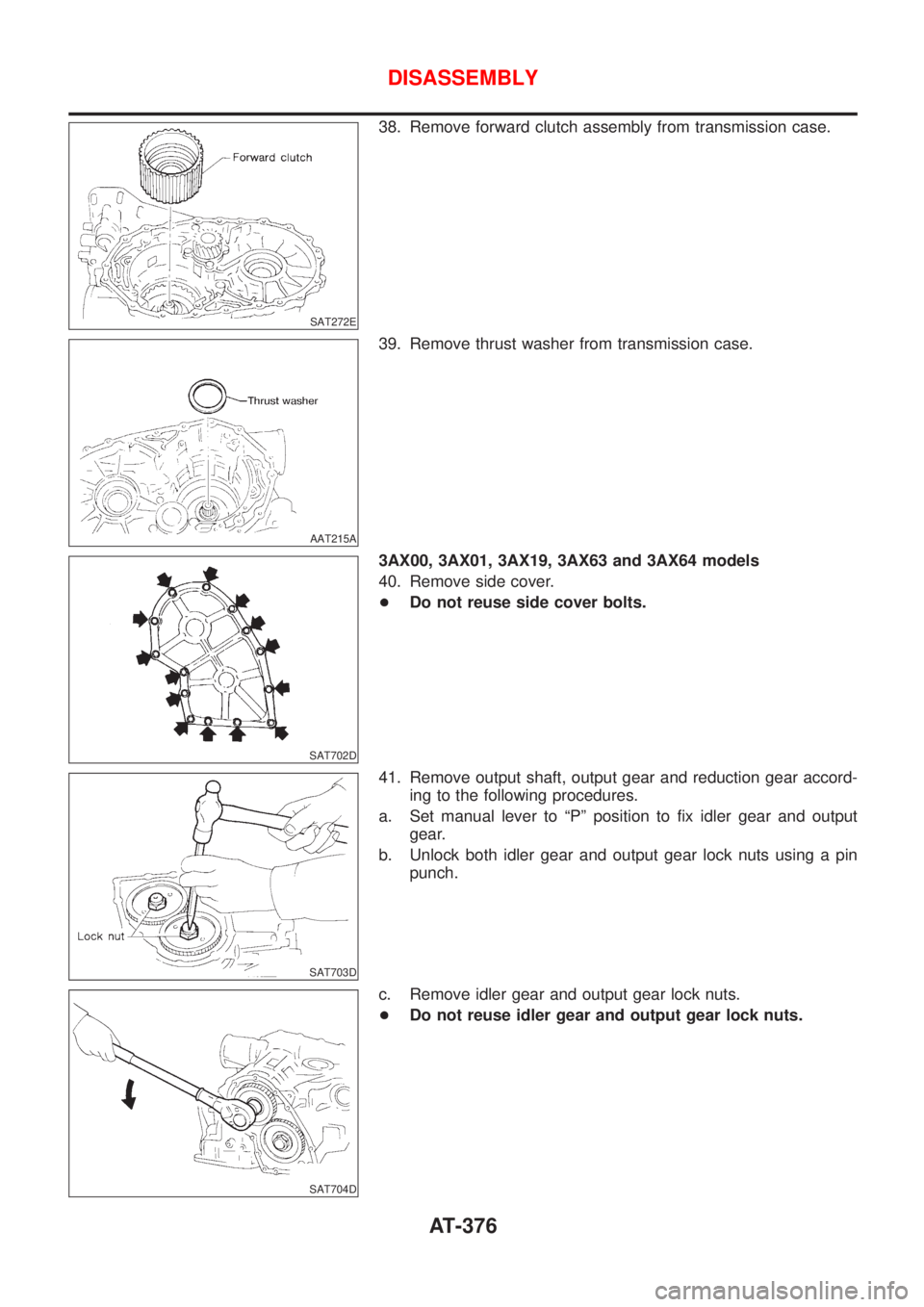
38. Remove forward clutch assembly from transmission case.
AAT215A
39. Remove thrust washer from transmission case.
SAT702D
3AX00, 3AX01, 3AX19, 3AX63 and 3AX64 models
40. Remove side cover.
+Do not reuse side cover bolts.
SAT703D
41. Remove output shaft, output gear and reduction gear accord-
ing to the following procedures.
a. Set manual lever to ªPº position to fix idler gear and output
gear.
b. Unlock both idler gear and output gear lock nuts using a pin
punch.
SAT704D
c. Remove idler gear and output gear lock nuts.
+Do not reuse idler gear and output gear lock nuts.
DISASSEMBLY
AT-376
Page 394 of 2898
SAT115D
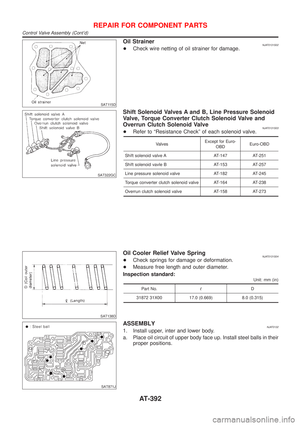
Oil StrainerNJAT0131S02+Check wire netting of oil strainer for damage.
SAT322GC
Shift Solenoid Valves A and B, Line Pressure Solenoid
Valve, Torque Converter Clutch Solenoid Valve and
Overrun Clutch Solenoid Valve
NJAT0131S03+Refer to ªResistance Checkº of each solenoid valve.
ValvesExcept for Euro-
OBDEuro-OBD
Shift solenoid valve A AT-147 AT-251
Shift solenoid vavle B AT-153 AT-257
Line pressure solenoid valve AT-182 AT-245
Torque converter clutch solenoid valve AT-164 AT-238
Overrun clutch solenoid valve AT-158 AT-273
SAT138D
Oil Cooler Relief Valve SpringNJAT0131S04+Check springs for damage or deformation.
+Measure free length and outer diameter.
Inspection standard:
Unit: mm (in)
Part No.!D
31872 31X00 17.0 (0.669) 8.0 (0.315)
SAT871J
ASSEMBLYNJAT01321. Install upper, inter and lower body.
a. Place oil circuit of upper body face up. Install steel balls in their
proper positions.
REPAIR FOR COMPONENT PARTS
Control Valve Assembly (Cont'd)
AT-392
Page 399 of 2898
Control Valve Upper Body
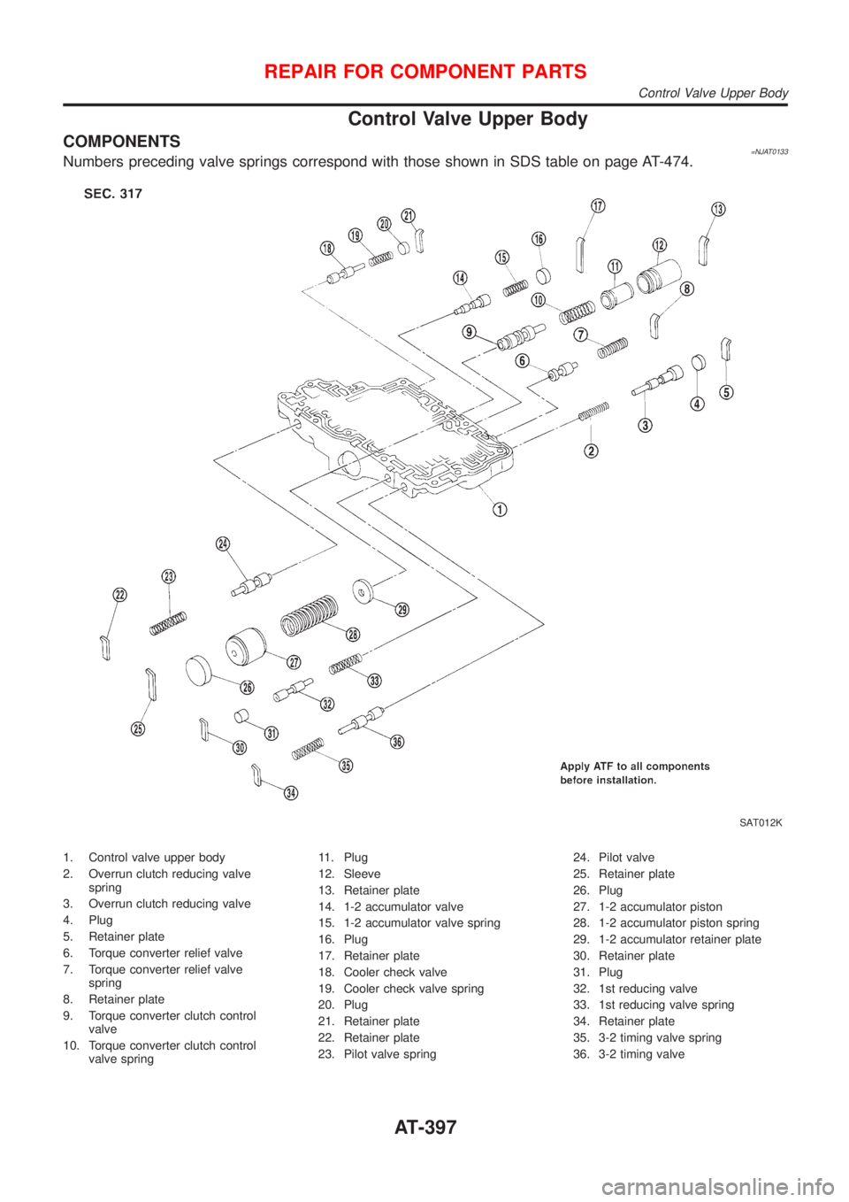
COMPONENTS=NJAT0133Numbers preceding valve springs correspond with those shown in SDS table on page AT-474.
SAT012K
1. Control valve upper body
2. Overrun clutch reducing valve
spring
3. Overrun clutch reducing valve
4. Plug
5. Retainer plate
6. Torque converter relief valve
7. Torque converter relief valve
spring
8. Retainer plate
9. Torque converter clutch control
valve
10. Torque converter clutch control
valve spring11. Plug
12. Sleeve
13. Retainer plate
14. 1-2 accumulator valve
15. 1-2 accumulator valve spring
16. Plug
17. Retainer plate
18. Cooler check valve
19. Cooler check valve spring
20. Plug
21. Retainer plate
22. Retainer plate
23. Pilot valve spring24. Pilot valve
25. Retainer plate
26. Plug
27. 1-2 accumulator piston
28. 1-2 accumulator piston spring
29. 1-2 accumulator retainer plate
30. Retainer plate
31. Plug
32. 1st reducing valve
33. 1st reducing valve spring
34. Retainer plate
35. 3-2 timing valve spring
36. 3-2 timing valve
REPAIR FOR COMPONENT PARTS
Control Valve Upper Body
AT-397
Page 402 of 2898
SAT086F
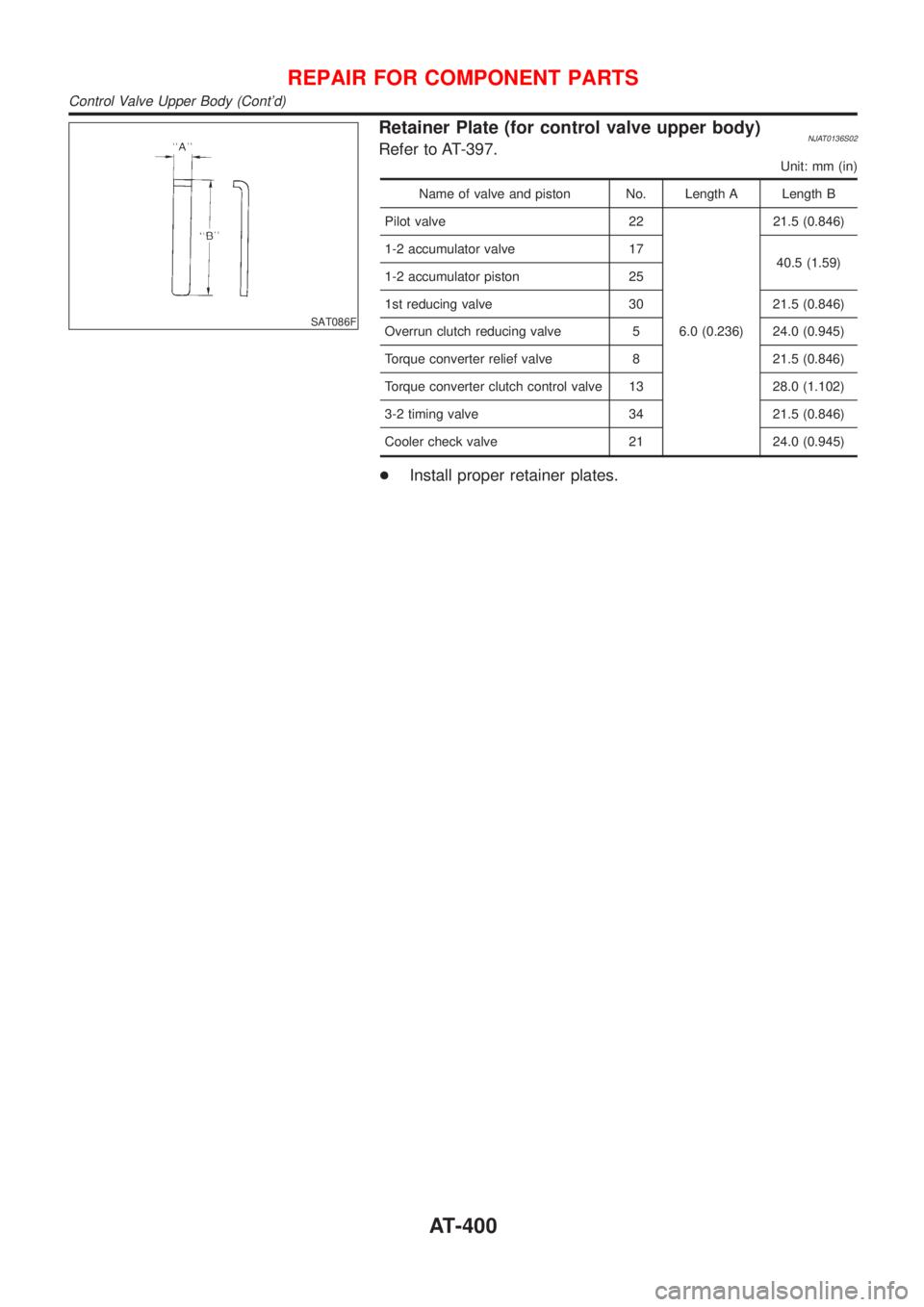
Retainer Plate (for control valve upper body)NJAT0136S02Refer to AT-397.
Unit: mm (in)
Name of valve and piston No. Length A Length B
Pilot valve 22
6.0 (0.236)21.5 (0.846)
1-2 accumulator valve 17
40.5 (1.59)
1-2 accumulator piston 25
1st reducing valve 30 21.5 (0.846)
Overrun clutch reducing valve 5 24.0 (0.945)
Torque converter relief valve 8 21.5 (0.846)
Torque converter clutch control valve 13 28.0 (1.102)
3-2 timing valve 34 21.5 (0.846)
Cooler check valve 21 24.0 (0.945)
+Install proper retainer plates.
REPAIR FOR COMPONENT PARTS
Control Valve Upper Body (Cont'd)
AT-400
Page 403 of 2898
Control Valve Lower Body
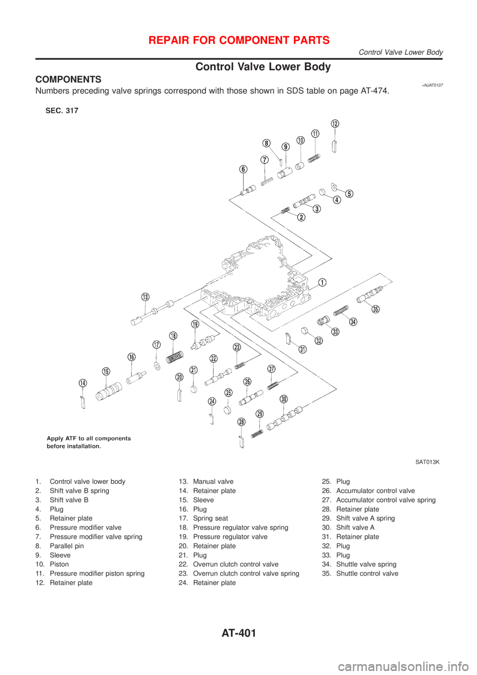
COMPONENTS=NJAT0137Numbers preceding valve springs correspond with those shown in SDS table on page AT-474.
SAT013K
1. Control valve lower body
2. Shift valve B spring
3. Shift valve B
4. Plug
5. Retainer plate
6. Pressure modifier valve
7. Pressure modifier valve spring
8. Parallel pin
9. Sleeve
10. Piston
11. Pressure modifier piston spring
12. Retainer plate13. Manual valve
14. Retainer plate
15. Sleeve
16. Plug
17. Spring seat
18. Pressure regulator valve spring
19. Pressure regulator valve
20. Retainer plate
21. Plug
22. Overrun clutch control valve
23. Overrun clutch control valve spring
24. Retainer plate25. Plug
26. Accumulator control valve
27. Accumulator control valve spring
28. Retainer plate
29. Shift valve A spring
30. Shift valve A
31. Retainer plate
32. Plug
33. Plug
34. Shuttle valve spring
35. Shuttle control valve
REPAIR FOR COMPONENT PARTS
Control Valve Lower Body
AT-401
Page 404 of 2898
SAT872J
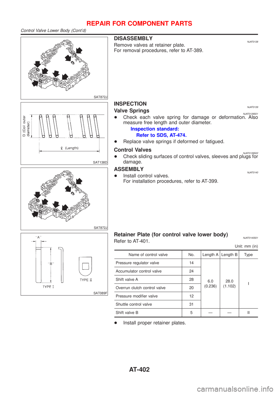
DISASSEMBLYNJAT0138Remove valves at retainer plate.
For removal procedures, refer to AT-389.
SAT138D
INSPECTIONNJAT0139Valve SpringsNJAT0139S01+Check each valve spring for damage or deformation. Also
measure free length and outer diameter.
Inspection standard:
Refer to SDS, AT-474.
+Replace valve springs if deformed or fatigued.
Control ValvesNJAT0139S02+Check sliding surfaces of control valves, sleeves and plugs for
damage.
SAT872J
ASSEMBLYNJAT0140+Install control valves.
For installation procedures, refer to AT-399.
SAT089F
Retainer Plate (for control valve lower body)NJAT0140S01Refer to AT-401.
Unit: mm (in)
Name of control valve No. Length A Length B Type
Pressure regulator valve 14
6.0
(0.236)28.0
(1.102)I Accumulator control valve 24
Shift valve A 28
Overrun clutch control valve 20
Pressure modifier valve 12
Shuttle control valve 31
Shift valve B 5 Ð Ð II
+Install proper retainer plates.
REPAIR FOR COMPONENT PARTS
Control Valve Lower Body (Cont'd)
AT-402
Page 405 of 2898
Reverse Clutch
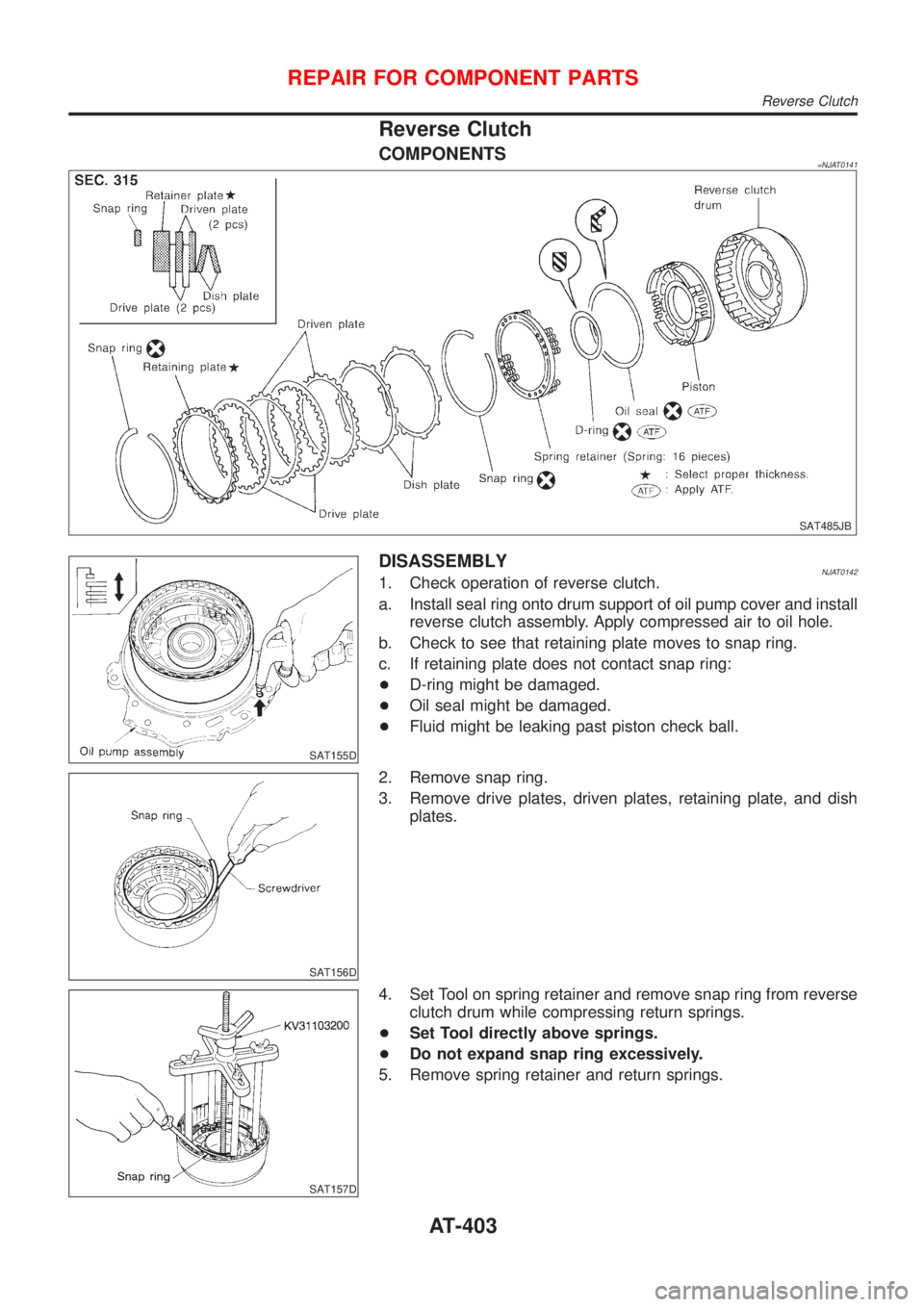
COMPONENTS=NJAT0141
SAT485JB
SAT155D
DISASSEMBLYNJAT01421. Check operation of reverse clutch.
a. Install seal ring onto drum support of oil pump cover and install
reverse clutch assembly. Apply compressed air to oil hole.
b. Check to see that retaining plate moves to snap ring.
c. If retaining plate does not contact snap ring:
+D-ring might be damaged.
+Oil seal might be damaged.
+Fluid might be leaking past piston check ball.
SAT156D
2. Remove snap ring.
3. Remove drive plates, driven plates, retaining plate, and dish
plates.
SAT157D
4. Set Tool on spring retainer and remove snap ring from reverse
clutch drum while compressing return springs.
+Set Tool directly above springs.
+Do not expand snap ring excessively.
5. Remove spring retainer and return springs.
REPAIR FOR COMPONENT PARTS
Reverse Clutch
AT-403