NISSAN ALMERA 2001 Service Manual
ALMERA 2001
NISSAN
NISSAN
https://www.carmanualsonline.info/img/5/57348/w960_57348-0.png
NISSAN ALMERA 2001 Service Manual
Trending: oil change, ESP, tow, load capacity, washer fluid, coolant temperature, sat nav
Page 1891 of 2898

KEY SWITCH (INSERT) CHECK=NJEL0505S11
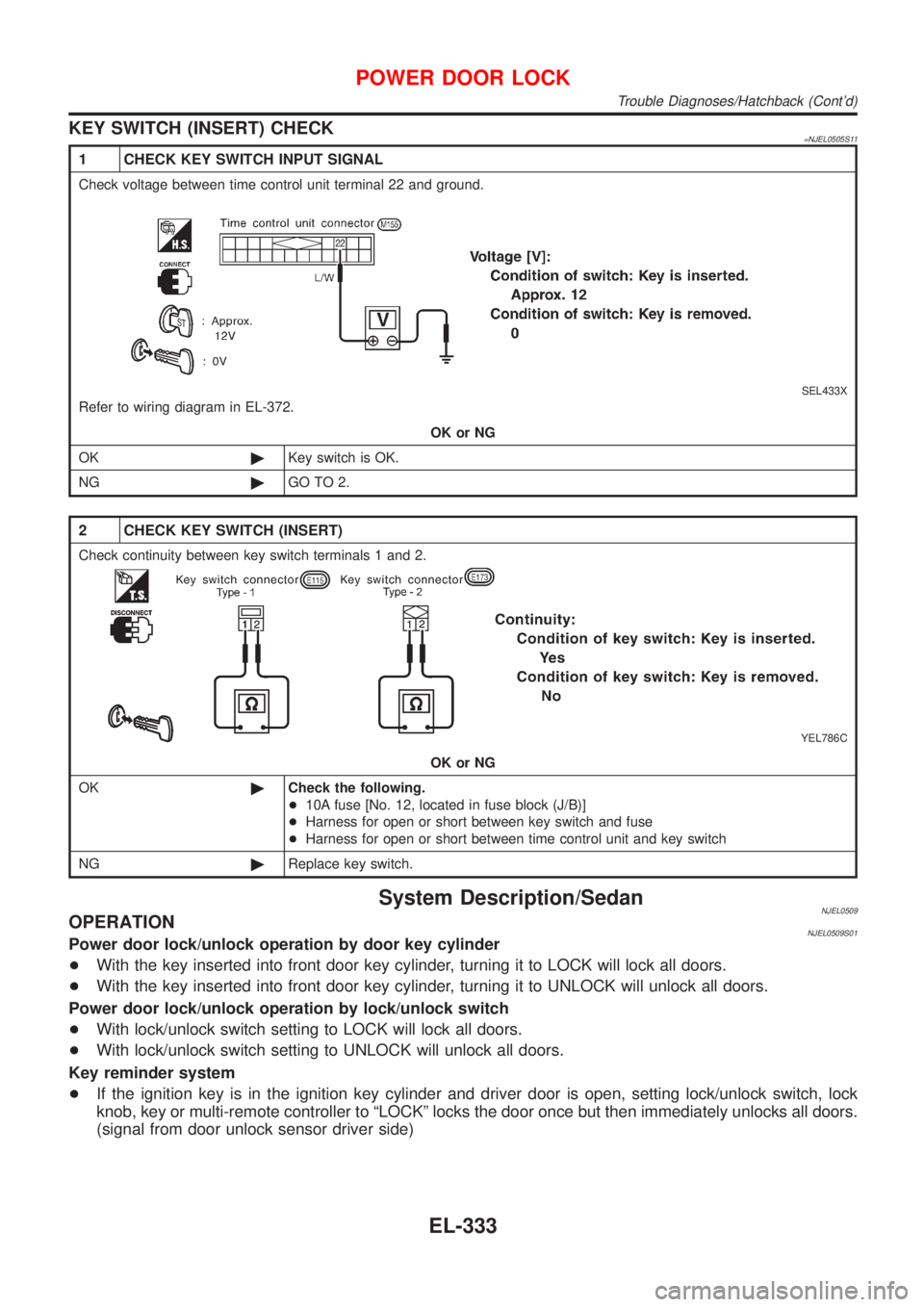
1 CHECK KEY SWITCH INPUT SIGNAL
Check voltage between time control unit terminal 22 and ground.
SEL433X
Refer to wiring diagram in EL-372.
OK or NG
OK©Key switch is OK.
NG©GO TO 2.
2 CHECK KEY SWITCH (INSERT)
Check continuity between key switch terminals 1 and 2.
YEL786C
OK or NG
OK©Check the following.
+10A fuse [No. 12, located in fuse block (J/B)]
+Harness for open or short between key switch and fuse
+Harness for open or short between time control unit and key switch
NG©Replace key switch.
System Description/SedanNJEL0509OPERATIONNJEL0509S01Power door lock/unlock operation by door key cylinder
+With the key inserted into front door key cylinder, turning it to LOCK will lock all doors.
+With the key inserted into front door key cylinder, turning it to UNLOCK will unlock all doors.
Power door lock/unlock operation by lock/unlock switch
+With lock/unlock switch setting to LOCK will lock all doors.
+With lock/unlock switch setting to UNLOCK will unlock all doors.
Key reminder system
+If the ignition key is in the ignition key cylinder and driver door is open, setting lock/unlock switch, lock
knob, key or multi-remote controller to ªLOCKº locks the door once but then immediately unlocks all doors.
(signal from door unlock sensor driver side)
POWER DOOR LOCK
Trouble Diagnoses/Hatchback (Cont'd)
EL-333
Page 1892 of 2898
Schematic/SedanNJEL0510
HEL411B
POWER DOOR LOCK
Schematic/Sedan
EL-334
Page 1893 of 2898
Wiring Diagram Ð D/LOCK Ð/SedanNJEL0511FIG. 1NJEL0511S01
HEL412B
POWER DOOR LOCK
Wiring Diagram Ð D/LOCK Ð/Sedan
EL-335
Page 1894 of 2898
FIG. 2NJEL0511S02
HEL413B
POWER DOOR LOCK
Wiring Diagram Ð D/LOCK Ð/Sedan (Cont'd)
EL-336
Page 1895 of 2898
FIG. 3NJEL0511S03
HEL414B
POWER DOOR LOCK
Wiring Diagram Ð D/LOCK Ð/Sedan (Cont'd)
EL-337
Page 1896 of 2898
FIG. 4NJEL0511S04
HEL415B
POWER DOOR LOCK
Wiring Diagram Ð D/LOCK Ð/Sedan (Cont'd)
EL-338
Page 1897 of 2898
FIG. 5NJEL0511S05
HEL455B
POWER DOOR LOCK
Wiring Diagram Ð D/LOCK Ð/Sedan (Cont'd)
EL-339
Page 1898 of 2898
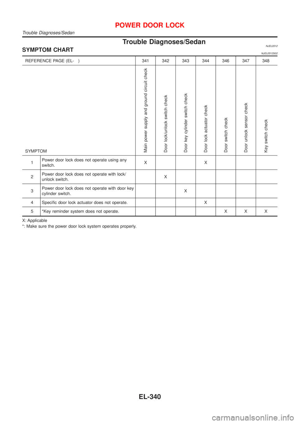
Trouble Diagnoses/SedanNJEL0512SYMPTOM CHARTNJEL0512S02
REFERENCE PAGE (EL- ) 341 342 343 344 346 347 348
SYMPTOM
Main power supply and ground circuit check
Door lock/unlock switch check
Door key cylinder switch check
Door lock actuator check
Door switch check
Door unlock sensor check
Key switch check
1Power door lock does not operate using any
switch.XX
2Power door lock does not operate with lock/
unlock switch.X
3Power door lock does not operate with door key
cylinder switch.X
4 Specific door lock actuator does not operate. X
5 *Key reminder system does not operate. X X X
X: Applicable
*: Make sure the power door lock system operates properly.
POWER DOOR LOCK
Trouble Diagnoses/Sedan
EL-340
Page 1899 of 2898
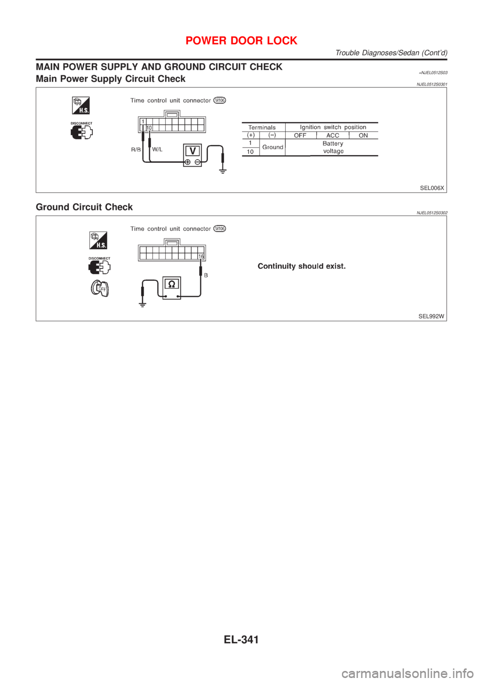
MAIN POWER SUPPLY AND GROUND CIRCUIT CHECK=NJEL0512S03Main Power Supply Circuit CheckNJEL0512S0301
SEL006X
Ground Circuit CheckNJEL0512S0302
SEL992W
POWER DOOR LOCK
Trouble Diagnoses/Sedan (Cont'd)
EL-341
Page 1900 of 2898
DOOR LOCK/UNLOCK SWITCH CHECK=NJEL0512S04
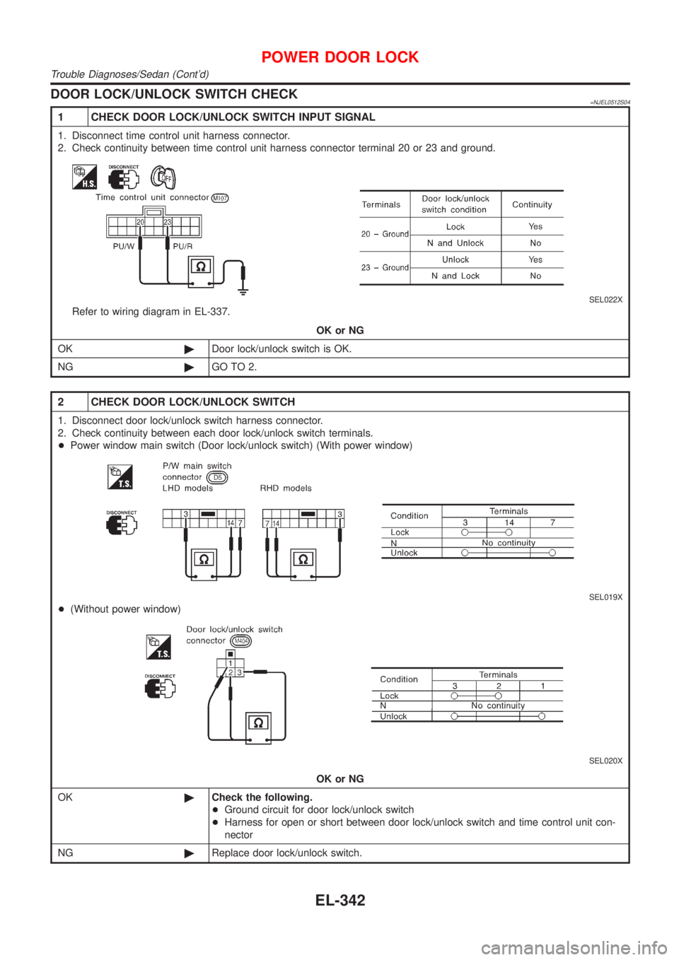
1 CHECK DOOR LOCK/UNLOCK SWITCH INPUT SIGNAL
1. Disconnect time control unit harness connector.
2. Check continuity between time control unit harness connector terminal 20 or 23 and ground.
SEL022X
Refer to wiring diagram in EL-337.
OK or NG
OK©Door lock/unlock switch is OK.
NG©GO TO 2.
2 CHECK DOOR LOCK/UNLOCK SWITCH
1. Disconnect door lock/unlock switch harness connector.
2. Check continuity between each door lock/unlock switch terminals.
+Power window main switch (Door lock/unlock switch) (With power window)
SEL019X
+(Without power window)
SEL020X
OK or NG
OK©Check the following.
+Ground circuit for door lock/unlock switch
+Harness for open or short between door lock/unlock switch and time control unit con-
nector
NG©Replace door lock/unlock switch.
POWER DOOR LOCK
Trouble Diagnoses/Sedan (Cont'd)
EL-342
Trending: fuel consumption, bolt pattern, rear view mirror, window, fog light, remove seats, ESP


