NISSAN ALMERA 2001 Service Manual
Manufacturer: NISSAN, Model Year: 2001, Model line: ALMERA, Model: NISSAN ALMERA 2001Pages: 2898, PDF Size: 60.76 MB
Page 2231 of 2898
JEM126G
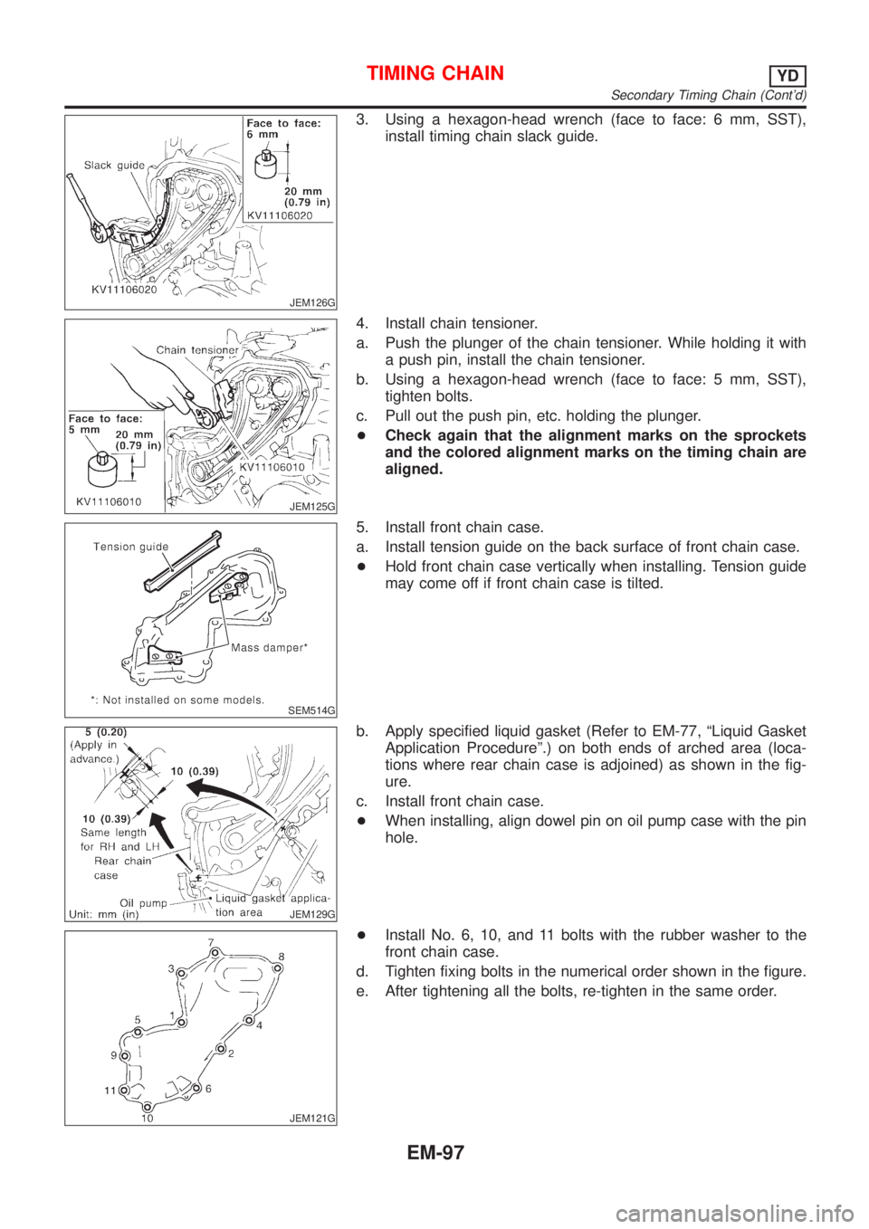
3. Using a hexagon-head wrench (face to face: 6 mm, SST),
install timing chain slack guide.
JEM125G
4. Install chain tensioner.
a. Push the plunger of the chain tensioner. While holding it with
a push pin, install the chain tensioner.
b. Using a hexagon-head wrench (face to face: 5 mm, SST),
tighten bolts.
c. Pull out the push pin, etc. holding the plunger.
+Check again that the alignment marks on the sprockets
and the colored alignment marks on the timing chain are
aligned.
SEM514G
5. Install front chain case.
a. Install tension guide on the back surface of front chain case.
+Hold front chain case vertically when installing. Tension guide
may come off if front chain case is tilted.
JEM129G
b. Apply specified liquid gasket (Refer to EM-77, ªLiquid Gasket
Application Procedureº.) on both ends of arched area (loca-
tions where rear chain case is adjoined) as shown in the fig-
ure.
c. Install front chain case.
+When installing, align dowel pin on oil pump case with the pin
hole.
JEM121G
+Install No. 6, 10, and 11 bolts with the rubber washer to the
front chain case.
d. Tighten fixing bolts in the numerical order shown in the figure.
e. After tightening all the bolts, re-tighten in the same order.
TIMING CHAINYD
Secondary Timing Chain (Cont'd)
EM-97
Page 2232 of 2898
6. Hereafter, install in the reverse order of removal.
TIMING CHAINYD
Secondary Timing Chain (Cont'd)
EM-98
Page 2233 of 2898
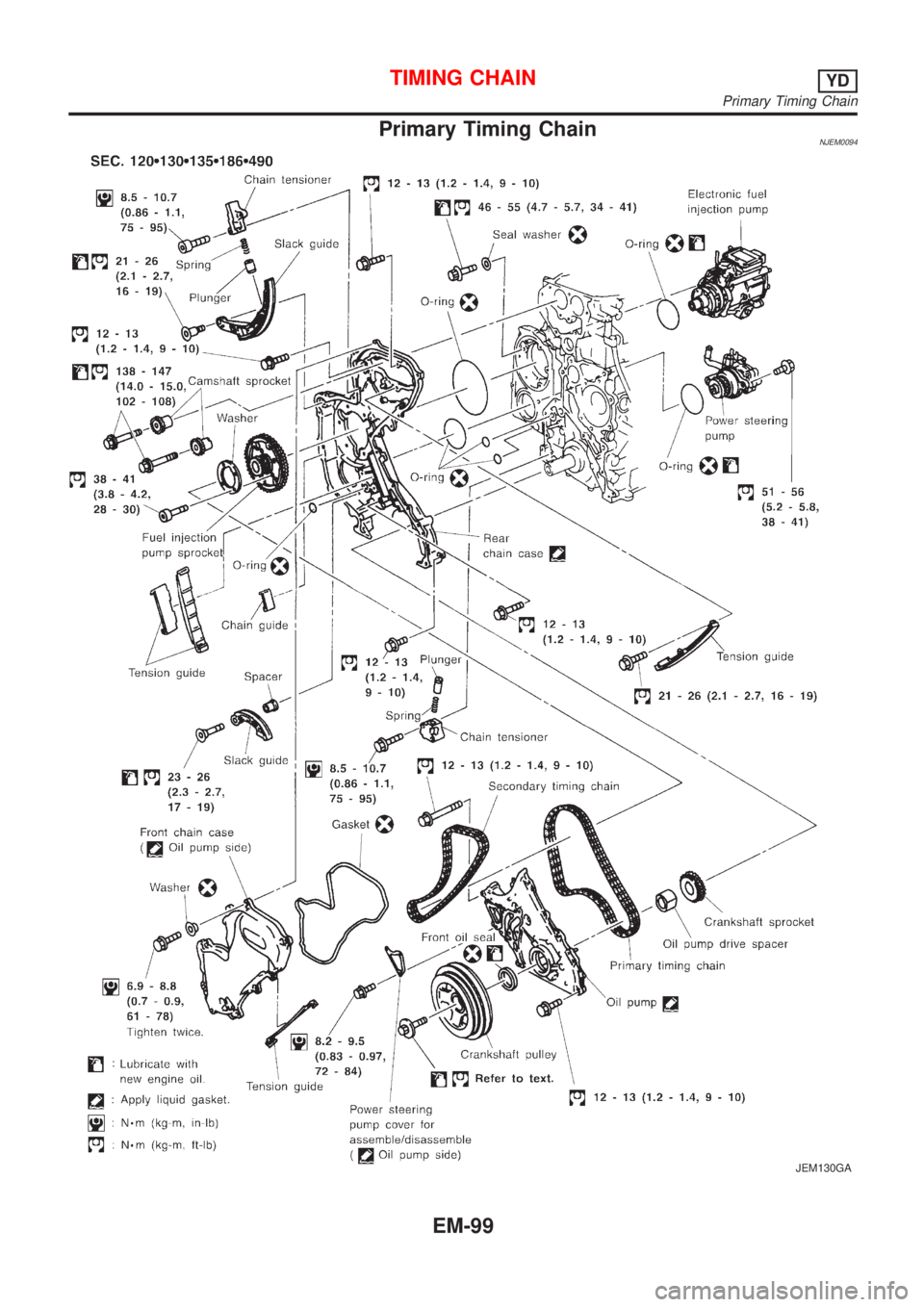
Primary Timing ChainNJEM0094
JEM130GA
TIMING CHAINYD
Primary Timing Chain
EM-99
Page 2234 of 2898
REMOVALNJEM0094S011. Remove engine and transaxle assembly. Refer to EM-137,
ªENGINE ASSEMBLYº.
2. Remove transaxle from engine. Place engine onto engine
stand (SST). Refer to EM-141, ªCYLINDER BLOCKº, ªDisas-
semblyº.
3. Remove the following parts:
+Oil pan (upper and lower)
Refer to EM-89, ªOIL PANº.
+Oil filter bracket
Refer to LC-32, ªOil Filter Bracketº.
+Injection tube
Refer to EC-614, ªInjection Tube and Injection Nozzleº.
4. Remove secondary timing chain and associated parts.
Refer to EM-94, ªSecondary Timing Chainº.
5. When removing rear chain case, remove camshaft sprockets.
Refer to EM-120, ªCAMSHAFTº.
JEM131G
6. Remove crankshaft pulley.
a. Hold crankshaft pulley with the pulley holder (SST).
b. Loosen crankshaft pulley fixing bolt and pull out the bolt
approximately 10 mm (0.39 in).
JEM132G
c. Using pulley puller (SST), remove crankshaft pulley.
+Use two M6 bolts with approx. 60 mm (2.36 in) shank length
for securing crankshaft pulley.
JEM133G
7. Remove oil pump.
+Loosen bolts in the reverse order of that shown in the figure
and remove them.
+Use seal cutter (SST) etc. for removal.
8. Remove front oil seal from oil pump.
+Punch out the seal off from the back surface of the oil pump
using a flat-bladed screwdriver.
+Be careful not to damage the oil pump.
TIMING CHAINYD
Primary Timing Chain (Cont'd)
EM-100
Page 2235 of 2898
JEM134G
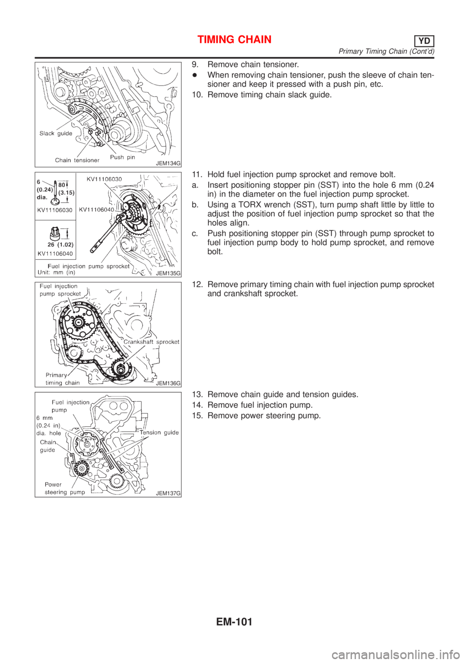
9. Remove chain tensioner.
+When removing chain tensioner, push the sleeve of chain ten-
sioner and keep it pressed with a push pin, etc.
10. Remove timing chain slack guide.
JEM135G
11. Hold fuel injection pump sprocket and remove bolt.
a. Insert positioning stopper pin (SST) into the hole 6 mm (0.24
in) in the diameter on the fuel injection pump sprocket.
b. Using a TORX wrench (SST), turn pump shaft little by little to
adjust the position of fuel injection pump sprocket so that the
holes align.
c. Push positioning stopper pin (SST) through pump sprocket to
fuel injection pump body to hold pump sprocket, and remove
bolt.
JEM136G
12. Remove primary timing chain with fuel injection pump sprocket
and crankshaft sprocket.
JEM137G
13. Remove chain guide and tension guides.
14. Remove fuel injection pump.
15. Remove power steering pump.
TIMING CHAINYD
Primary Timing Chain (Cont'd)
EM-101
Page 2236 of 2898
JEM138G
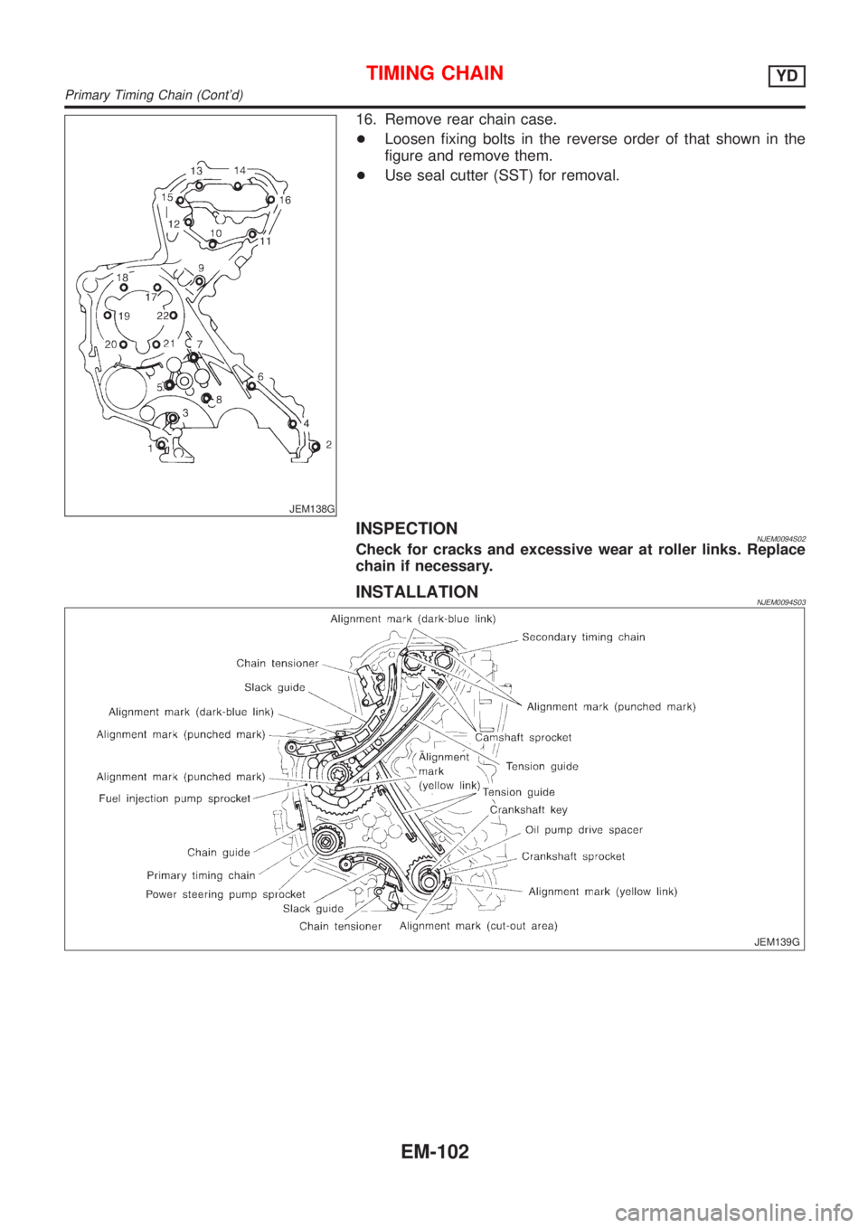
16. Remove rear chain case.
+Loosen fixing bolts in the reverse order of that shown in the
figure and remove them.
+Use seal cutter (SST) for removal.
INSPECTIONNJEM0094S02Check for cracks and excessive wear at roller links. Replace
chain if necessary.
INSTALLATIONNJEM0094S03
JEM139G
TIMING CHAINYD
Primary Timing Chain (Cont'd)
EM-102
Page 2237 of 2898
JEM140G
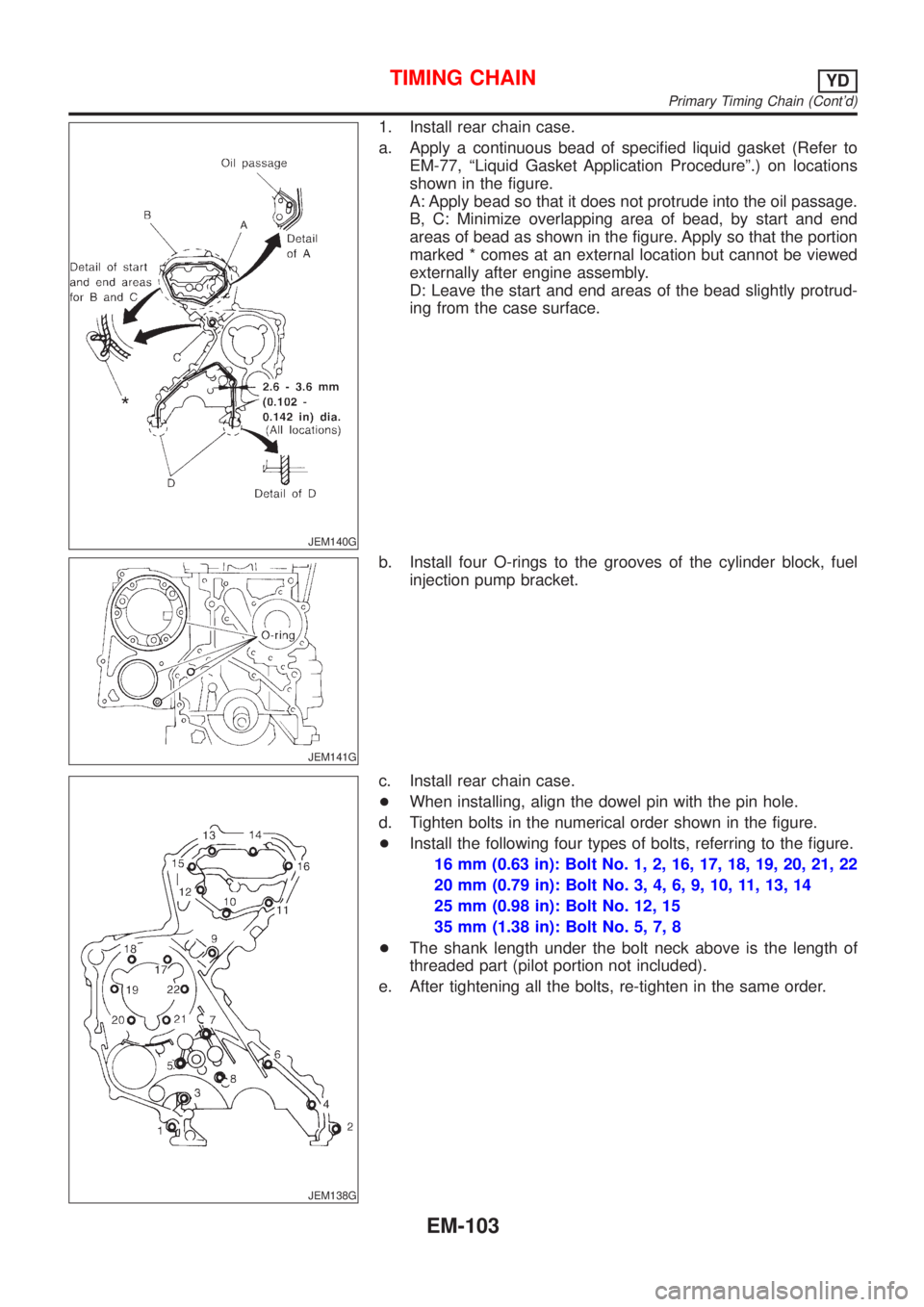
1. Install rear chain case.
a. Apply a continuous bead of specified liquid gasket (Refer to
EM-77, ªLiquid Gasket Application Procedureº.) on locations
shown in the figure.
A: Apply bead so that it does not protrude into the oil passage.
B, C: Minimize overlapping area of bead, by start and end
areas of bead as shown in the figure. Apply so that the portion
marked * comes at an external location but cannot be viewed
externally after engine assembly.
D: Leave the start and end areas of the bead slightly protrud-
ing from the case surface.
JEM141G
b. Install four O-rings to the grooves of the cylinder block, fuel
injection pump bracket.
JEM138G
c. Install rear chain case.
+When installing, align the dowel pin with the pin hole.
d. Tighten bolts in the numerical order shown in the figure.
+Install the following four types of bolts, referring to the figure.
16 mm (0.63 in): Bolt No. 1, 2, 16, 17, 18, 19, 20, 21, 22
20 mm (0.79 in): Bolt No. 3, 4, 6, 9, 10, 11, 13, 14
25 mm (0.98 in): Bolt No. 12, 15
35 mm (1.38 in): Bolt No. 5, 7, 8
+The shank length under the bolt neck above is the length of
threaded part (pilot portion not included).
e. After tightening all the bolts, re-tighten in the same order.
TIMING CHAINYD
Primary Timing Chain (Cont'd)
EM-103
Page 2238 of 2898
JEM137G
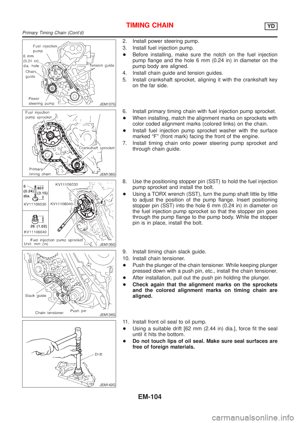
2. Install power steering pump.
3. Install fuel injection pump.
+Before installing, make sure the notch on the fuel injection
pump flange and the hole 6 mm (0.24 in) in diameter on the
pump body are aligned.
4. Install chain guide and tension guides.
5. Install crankshaft sprocket, aligning it with the crankshaft key
on the far side.
JEM136G
6. Install primary timing chain with fuel injection pump sprocket.
+When installing, match the alignment marks on sprockets with
color coded alignment marks (colored links) on the chain.
+Install fuel injection pump sprocket washer with the surface
marked ªFº (front mark) facing the front of the engine.
7. Install timing chain onto power steering pump sprocket and
through chain guide.
JEM135G
8. Use the positioning stopper pin (SST) to hold the fuel injection
pump sprocket and install the bolt.
+Using a TORX wrench (SST), turn the pump shaft little by little
to adjust the position of the pump flange. Insert positioning
stopper pin (SST) into the hole 6 mm (0.24 in) in diameter on
the fuel injection pump sprocket so that the stopper pin goes
through the pump flange to the pump body. While the stopper
pin is in place, install the bolt.
JEM134G
9. Install timing chain slack guide.
10. Install chain tensioner.
+Push the plunger of the chain tensioner. While keeping plunger
pressed down with a push pin, etc., install the chain tensioner.
+After installation, pull out the push pin holding the plunger.
+Check again that the alignment marks on the sprockets
and the colored alignment marks on timing chain are
aligned.
JEM142G
11. Install front oil seal to oil pump.
+Using a suitable drift [62 mm (2.44 in) dia.], force fit the seal
until it hits the bottom.
+Do not touch lips of oil seal. Make sure seal surfaces are
free of foreign materials.
TIMING CHAINYD
Primary Timing Chain (Cont'd)
EM-104
Page 2239 of 2898
JEM143G
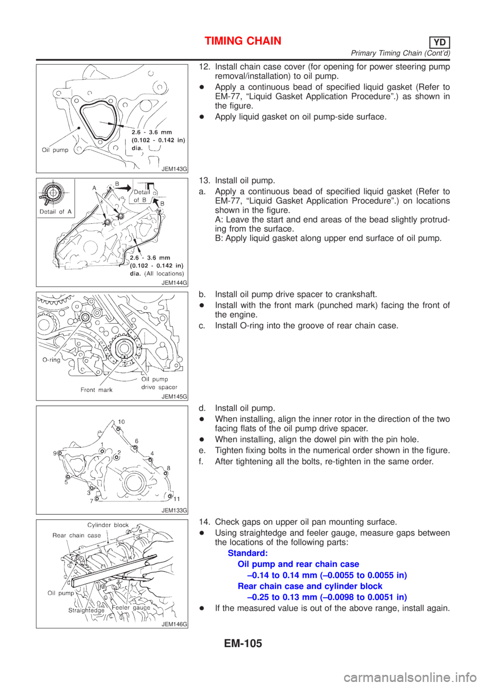
12. Install chain case cover (for opening for power steering pump
removal/installation) to oil pump.
+Apply a continuous bead of specified liquid gasket (Refer to
EM-77, ªLiquid Gasket Application Procedureº.) as shown in
the figure.
+Apply liquid gasket on oil pump-side surface.
JEM144G
13. Install oil pump.
a. Apply a continuous bead of specified liquid gasket (Refer to
EM-77, ªLiquid Gasket Application Procedureº.) on locations
shown in the figure.
A: Leave the start and end areas of the bead slightly protrud-
ing from the surface.
B: Apply liquid gasket along upper end surface of oil pump.
JEM145G
b. Install oil pump drive spacer to crankshaft.
+Install with the front mark (punched mark) facing the front of
the engine.
c. Install O-ring into the groove of rear chain case.
JEM133G
d. Install oil pump.
+When installing, align the inner rotor in the direction of the two
facing flats of the oil pump drive spacer.
+When installing, align the dowel pin with the pin hole.
e. Tighten fixing bolts in the numerical order shown in the figure.
f. After tightening all the bolts, re-tighten in the same order.
JEM146G
14. Check gaps on upper oil pan mounting surface.
+Using straightedge and feeler gauge, measure gaps between
the locations of the following parts:
Standard:
Oil pump and rear chain case
±0.14 to 0.14 mm (±0.0055 to 0.0055 in)
Rear chain case and cylinder block
±0.25 to 0.13 mm (±0.0098 to 0.0051 in)
+If the measured value is out of the above range, install again.
TIMING CHAINYD
Primary Timing Chain (Cont'd)
EM-105
Page 2240 of 2898
JEM147G
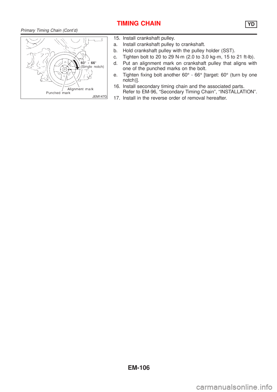
15. Install crankshaft pulley.
a. Install crankshaft pulley to crankshaft.
b. Hold crankshaft pulley with the pulley holder (SST).
c. Tighten bolt to 20 to 29 N´m (2.0 to 3.0 kg-m, 15 to 21 ft-lb).
d. Put an alignment mark on crankshaft pulley that aligns with
one of the punched marks on the bolt.
e. Tighten fixing bolt another 60É - 66É [target: 60É (turn by one
notch)].
16. Install secondary timing chain and the associated parts.
Refer to EM-96, ªSecondary Timing Chainº, ªINSTALLATIONº.
17. Install in the reverse order of removal hereafter.
TIMING CHAINYD
Primary Timing Chain (Cont'd)
EM-106