NISSAN ALMERA 2001 Service Manual
Manufacturer: NISSAN, Model Year: 2001, Model line: ALMERA, Model: NISSAN ALMERA 2001Pages: 2898, PDF Size: 60.76 MB
Page 2541 of 2898
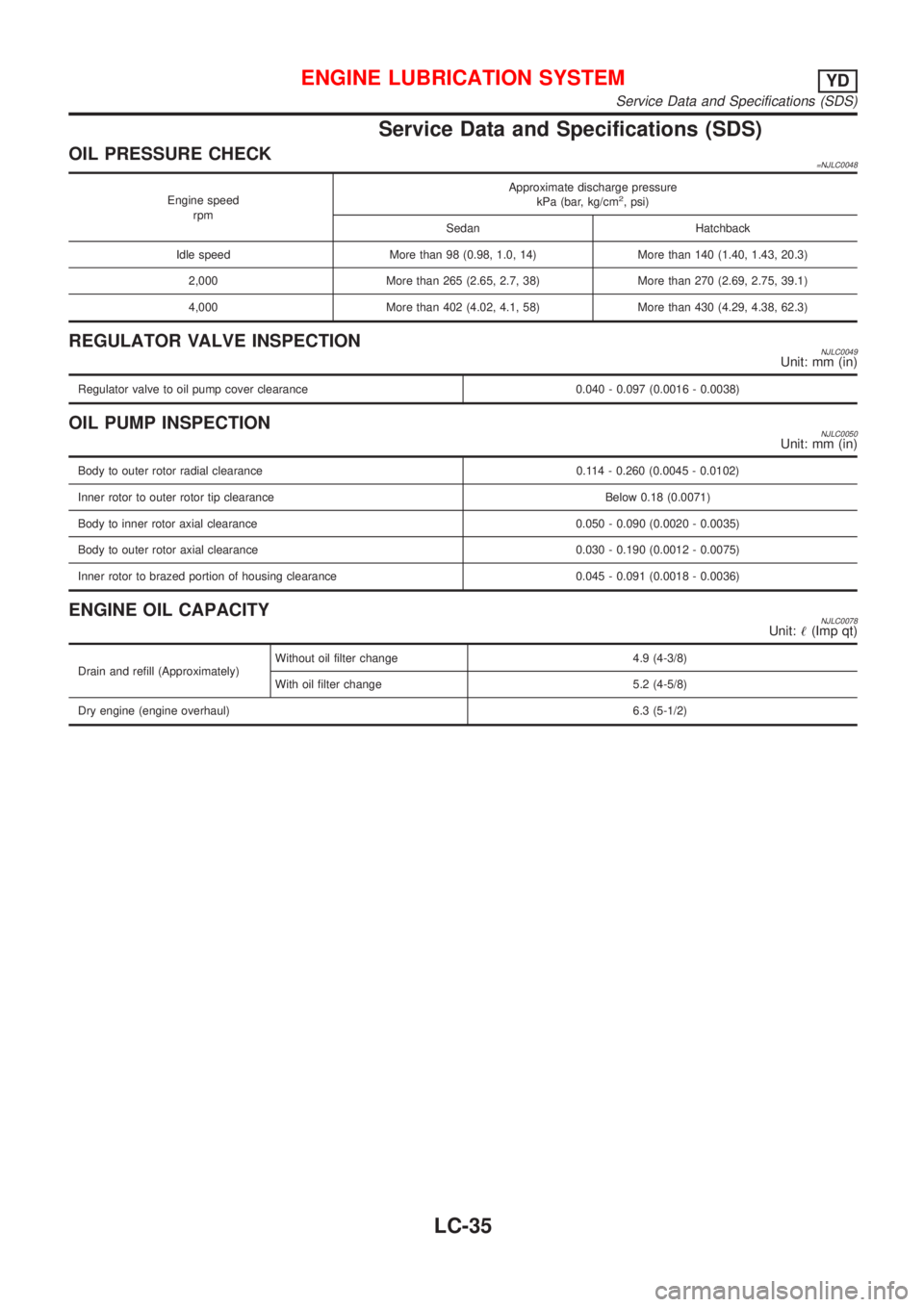
Service Data and Specifications (SDS)
OIL PRESSURE CHECK=NJLC0048
Engine speed
rpmApproximate discharge pressure
kPa (bar, kg/cm2, psi)
Sedan Hatchback
Idle speed More than 98 (0.98, 1.0, 14) More than 140 (1.40, 1.43, 20.3)
2,000 More than 265 (2.65, 2.7, 38) More than 270 (2.69, 2.75, 39.1)
4,000 More than 402 (4.02, 4.1, 58) More than 430 (4.29, 4.38, 62.3)
REGULATOR VALVE INSPECTIONNJLC0049Unit: mm (in)
Regulator valve to oil pump cover clearance 0.040 - 0.097 (0.0016 - 0.0038)
OIL PUMP INSPECTIONNJLC0050Unit: mm (in)
Body to outer rotor radial clearance 0.114 - 0.260 (0.0045 - 0.0102)
Inner rotor to outer rotor tip clearance Below 0.18 (0.0071)
Body to inner rotor axial clearance 0.050 - 0.090 (0.0020 - 0.0035)
Body to outer rotor axial clearance 0.030 - 0.190 (0.0012 - 0.0075)
Inner rotor to brazed portion of housing clearance 0.045 - 0.091 (0.0018 - 0.0036)
ENGINE OIL CAPACITYNJLC0078Unit:!(Imp qt)
Drain and refill (Approximately)Without oil filter change 4.9 (4-3/8)
With oil filter change 5.2 (4-5/8)
Dry engine (engine overhaul)6.3 (5-1/2)
ENGINE LUBRICATION SYSTEMYD
Service Data and Specifications (SDS)
LC-35
Page 2542 of 2898
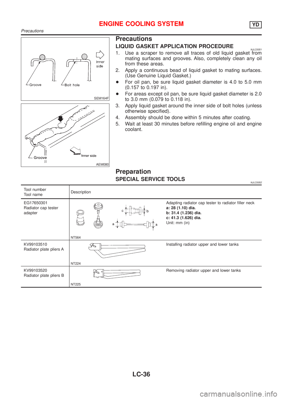
SEM164F
AEM080
Precautions
LIQUID GASKET APPLICATION PROCEDURENJLC00511. Use a scraper to remove all traces of old liquid gasket from
mating surfaces and grooves. Also, completely clean any oil
from these areas.
2. Apply a continuous bead of liquid gasket to mating surfaces.
(Use Genuine Liquid Gasket.)
+For oil pan, be sure liquid gasket diameter is 4.0 to 5.0 mm
(0.157 to 0.197 in).
+For areas except oil pan, be sure liquid gasket diameter is 2.0
to 3.0 mm (0.079 to 0.118 in).
3. Apply liquid gasket around the inner side of bolt holes (unless
otherwise specified).
4. Assembly should be done within 5 minutes after coating.
5. Wait at least 30 minutes before refilling engine oil and engine
coolant.
Preparation
SPECIAL SERVICE TOOLSNJLC0052
Tool number
Tool nameDescription
EG17650301
Radiator cap tester
adapter
NT564
Adapting radiator cap tester to radiator filler neck
a: 28 (1.10) dia.
b: 31.4 (1.236) dia.
c: 41.3 (1.626) dia.
Unit: mm (in)
KV99103510
Radiator plate pliers A
NT224
Installing radiator upper and lower tanks
KV99103520
Radiator plate pliers B
NT225
Removing radiator upper and lower tanks
ENGINE COOLING SYSTEMYD
Precautions
LC-36
Page 2543 of 2898
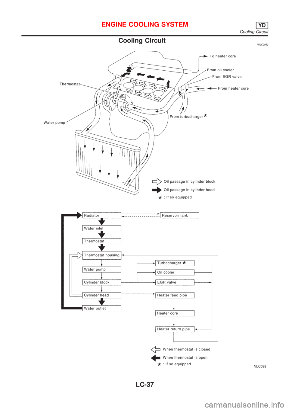
Cooling CircuitNJLC0053
NLC098
ENGINE COOLING SYSTEMYD
Cooling Circuit
LC-37
Page 2544 of 2898
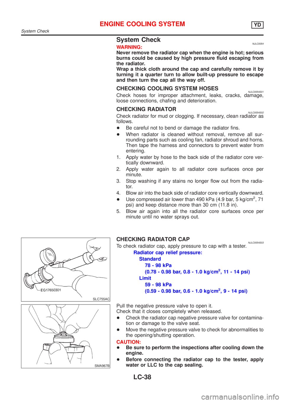
System CheckNJLC0054WARNING:
Never remove the radiator cap when the engine is hot; serious
burns could be caused by high pressure fluid escaping from
the radiator.
Wrap a thick cloth around the cap and carefully remove it by
turning it a quarter turn to allow built-up pressure to escape
and then turn the cap all the way off.
CHECKING COOLING SYSTEM HOSESNJLC0054S01Check hoses for improper attachment, leaks, cracks, damage,
loose connections, chafing and deterioration.
CHECKING RADIATORNJLC0054S02Check radiator for mud or clogging. If necessary, clean radiator as
follows.
+Be careful not to bend or damage the radiator fins.
+When radiator is cleaned without removal, remove all sur-
rounding parts such as cooling fan, radiator shroud and horns.
Then tape the harness and connectors to prevent water from
entering.
1. Apply water by hose to the back side of the radiator core ver-
tically downward.
2. Apply water again to all radiator core surfaces once per
minute.
3. Stop washing if any stains no longer flow out from the radia-
tor.
4. Blow air into the back side of radiator core vertically downward.
+Use compressed air lower than 490 kPa (4.9 bar, 5 kg/cm
2,71
psi) and keep distance more than 30 cm (11.8 in).
5. Blow air again into all the radiator core surfaces once per
minute until no water sprays out.
SLC755AC
CHECKING RADIATOR CAPNJLC0054S03To check radiator cap, apply pressure to cap with a tester.
Radiator cap relief pressure:
Standard
78-98kPa
(0.78 - 0.98 bar, 0.8 - 1.0 kg/cm
2, 11 - 14 psi)
Limit
59-98kPa
(0.59 - 0.98 bar, 0.6 - 1.0 kg/cm
2,9-14psi)
SMA967B
Pull the negative pressure valve to open it.
Check that it closes completely when released.
+Check the radiator cap negative pressure valve for contamina-
tion or damage to the valve seat.
+Move the negative pressure valve to check for abnormalities to
the opening/shutting operation.
CAUTION:
+Be sure to perform the inspections after cooling down the
engine.
+Before connecting the radiator cap to the tester, apply
water or LLC to the cap sealing.
ENGINE COOLING SYSTEMYD
System Check
LC-38
Page 2545 of 2898
+Replace the radiator cap if abnormalities are found with the
negative pressure valve, or if the valve opening pressure is out
of the standard range.
SLC756AA
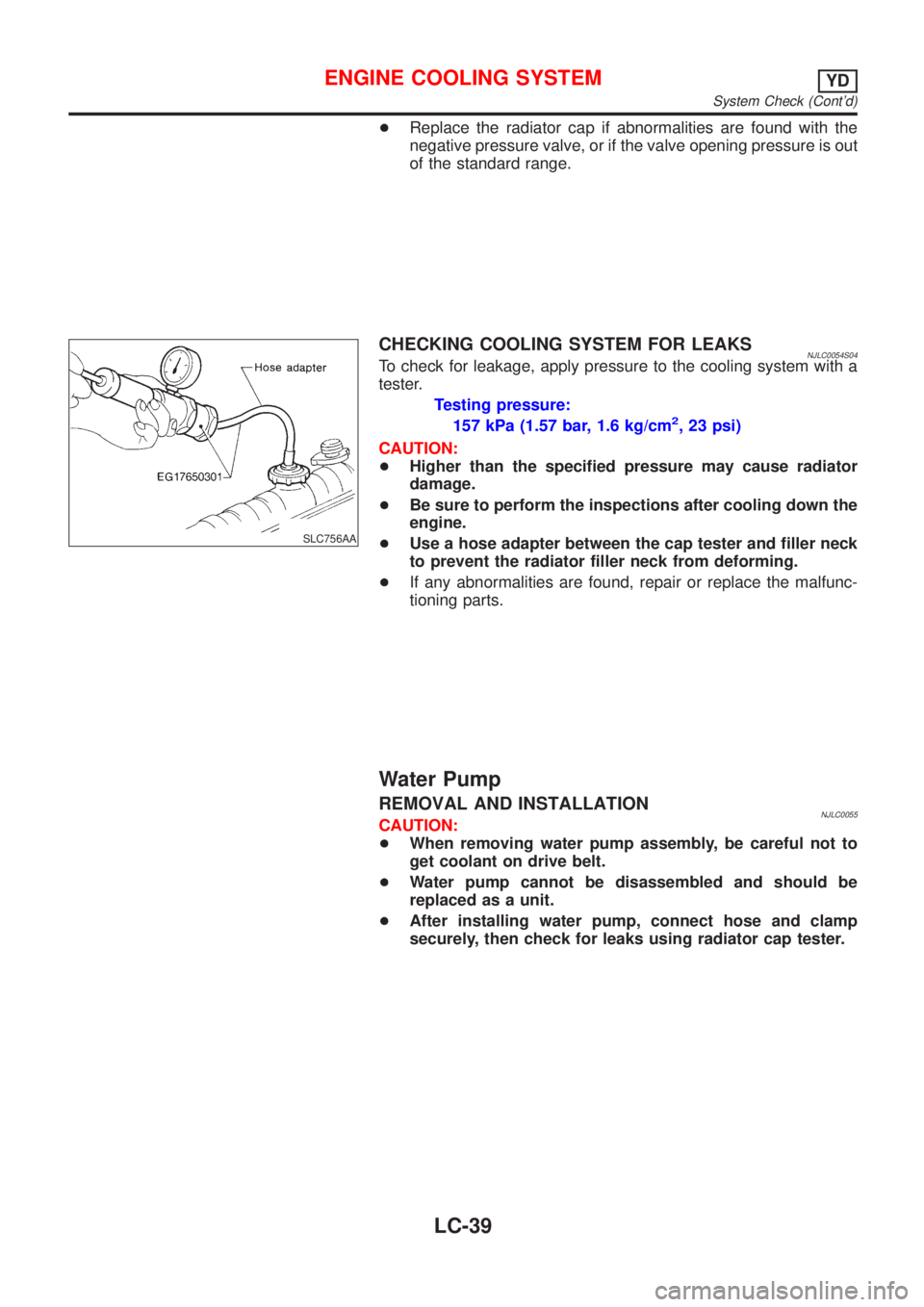
CHECKING COOLING SYSTEM FOR LEAKSNJLC0054S04To check for leakage, apply pressure to the cooling system with a
tester.
Testing pressure:
157 kPa (1.57 bar, 1.6 kg/cm
2, 23 psi)
CAUTION:
+Higher than the specified pressure may cause radiator
damage.
+Be sure to perform the inspections after cooling down the
engine.
+Use a hose adapter between the cap tester and filler neck
to prevent the radiator filler neck from deforming.
+If any abnormalities are found, repair or replace the malfunc-
tioning parts.
Water Pump
REMOVAL AND INSTALLATIONNJLC0055CAUTION:
+When removing water pump assembly, be careful not to
get coolant on drive belt.
+Water pump cannot be disassembled and should be
replaced as a unit.
+After installing water pump, connect hose and clamp
securely, then check for leaks using radiator cap tester.
ENGINE COOLING SYSTEMYD
System Check (Cont'd)
LC-39
Page 2546 of 2898
JLC294B
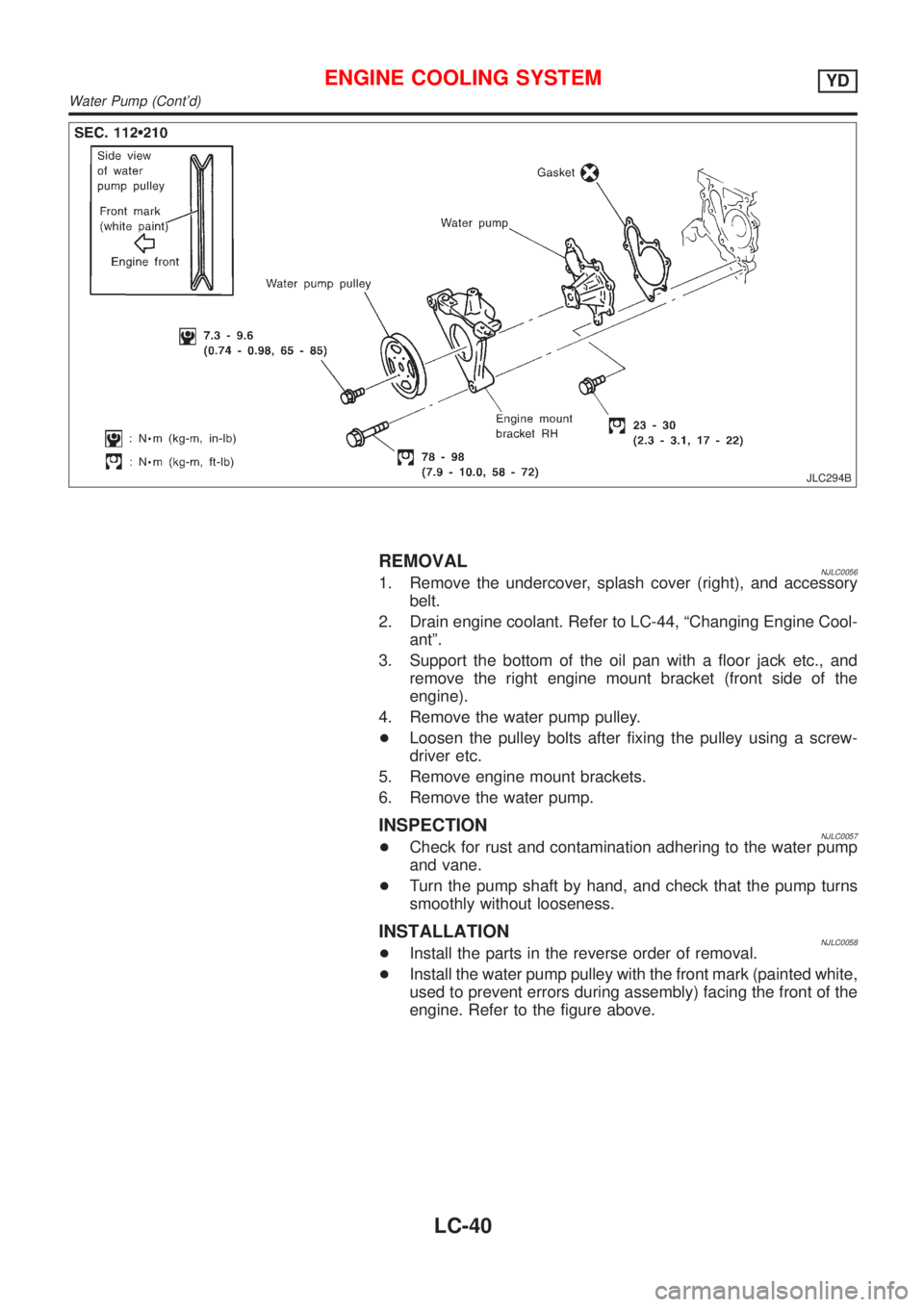
REMOVALNJLC00561. Remove the undercover, splash cover (right), and accessory
belt.
2. Drain engine coolant. Refer to LC-44, ªChanging Engine Cool-
antº.
3. Support the bottom of the oil pan with a floor jack etc., and
remove the right engine mount bracket (front side of the
engine).
4. Remove the water pump pulley.
+Loosen the pulley bolts after fixing the pulley using a screw-
driver etc.
5. Remove engine mount brackets.
6. Remove the water pump.
INSPECTIONNJLC0057+Check for rust and contamination adhering to the water pump
and vane.
+Turn the pump shaft by hand, and check that the pump turns
smoothly without looseness.
INSTALLATIONNJLC0058+Install the parts in the reverse order of removal.
+Install the water pump pulley with the front mark (painted white,
used to prevent errors during assembly) facing the front of the
engine. Refer to the figure above.
ENGINE COOLING SYSTEMYD
Water Pump (Cont'd)
LC-40
Page 2547 of 2898
Thermostat
REMOVAL AND INSTALLATIONNJLC0059
NLC099
+Be careful not to spill coolant over engine compartment.
Use a rag to absorb coolant.
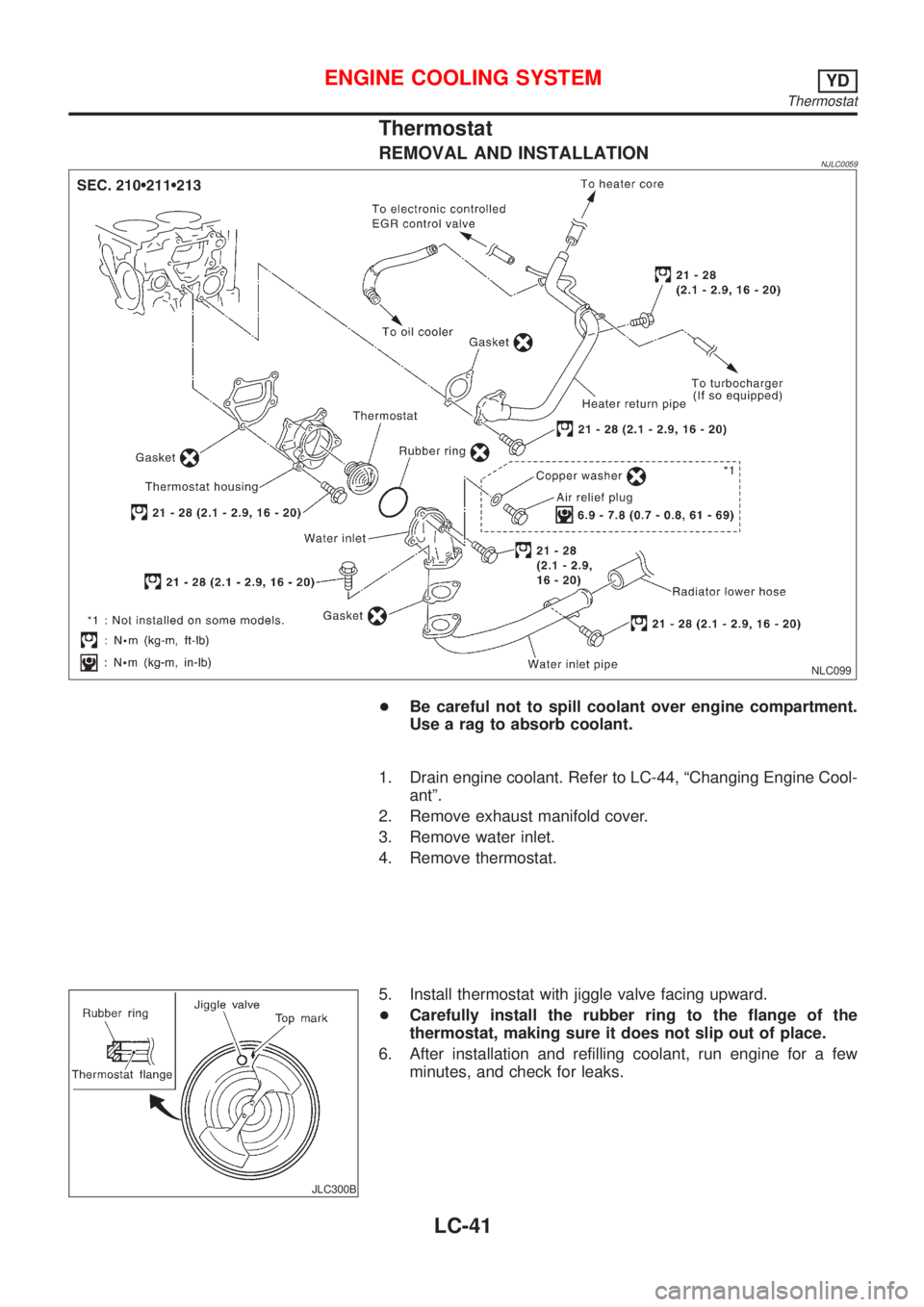
1. Drain engine coolant. Refer to LC-44, ªChanging Engine Cool-
antº.
2. Remove exhaust manifold cover.
3. Remove water inlet.
4. Remove thermostat.
JLC300B
5. Install thermostat with jiggle valve facing upward.
+Carefully install the rubber ring to the flange of the
thermostat, making sure it does not slip out of place.
6. After installation and refilling coolant, run engine for a few
minutes, and check for leaks.
ENGINE COOLING SYSTEMYD
Thermostat
LC-41
Page 2548 of 2898
SLC252B
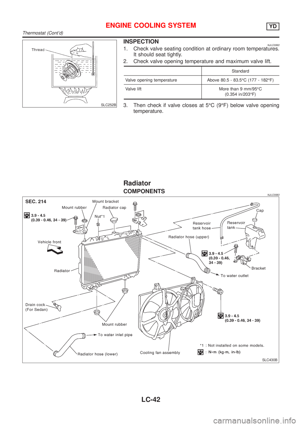
INSPECTIONNJLC00601. Check valve seating condition at ordinary room temperatures.
It should seat tightly.
2. Check valve opening temperature and maximum valve lift.
Standard
Valve opening temperature Above 80.5 - 83.5ÉC (177 - 182ÉF)
Valve lift More than 9 mm/95ÉC
(0.354 in/203ÉF)
3. Then check if valve closes at 5ÉC (9ÉF) below valve opening
temperature.
Radiator
COMPONENTSNJLC0083
SLC430B
ENGINE COOLING SYSTEMYD
Thermostat (Cont'd)
LC-42
Page 2549 of 2898
REMOVAL AND INSTALLATION=NJLC00631. Remove under cover.
2. For Sedan, drain coolant from radiator by drain cock, and for
Hatchback, drain coolant by removing lower radiator hose.
3. Disconnect radiator upper and lower hoses.
4. Remove radiator shroud.
5. Disconnect reservoir tank hose.
6. Remove radiator mounting bracket.
7. Remove radiator.
8. After repairing or replacing radiator, install any part removed in
reverse order of removal.
When filling radiator with coolant, refer to LC-44, ªChanging
Engine Coolantº.
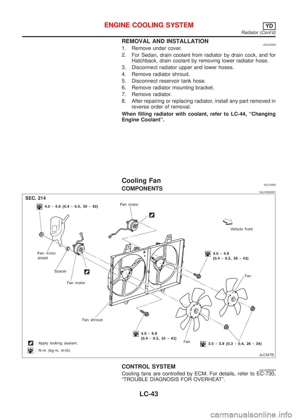
Cooling FanNJLC0064COMPONENTSNJLC0064S01
JLC347B
CONTROL SYSTEMNJLC0064S02Cooling fans are controlled by ECM. For details, refer to EC-730,
ªTROUBLE DIAGNOSIS FOR OVERHEATº.
ENGINE COOLING SYSTEMYD
Radiator (Cont'd)
LC-43
Page 2550 of 2898
SLC344B
JLC295B
Changing Engine CoolantNJLC0079WARNING:
To avoid the danger of being scalded, never change the cool-
ant when the engine is hot.
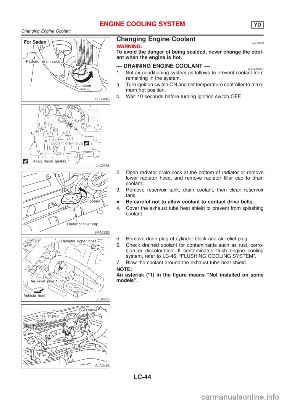
Ð DRAINING ENGINE COOLANT ÐNJLC0079S011. Set air conditioning system as follows to prevent coolant from
remaining in the system.
a. Turn ignition switch ON and set temperature controller to maxi-
mum hot position.
b. Wait 10 seconds before turning ignition switch OFF.
SMA033D
2. Open radiator drain cock at the bottom of radiator or remove
lower radiator hose, and remove radiator filler cap to drain
coolant.
3. Remove reservoir tank, drain coolant, then clean reservoir
tank.
+Be careful not to allow coolant to contact drive belts.
4. Cover the exhaust tube heat shield to prevent from splashing
coolant.
JLC429B
SLC341B
5. Remove drain plug of cylinder block and air relief plug.
6. Check drained coolant for contaminants such as rust, corro-
sion or discoloration. If contaminated flush engine cooling
system, refer to LC-46, ªFLUSHING COOLING SYSTEMº.
7. Blow the coolant around the exhaust tube heat shield.
NOTE:
An asterisk (*1) in the figure means ªNot installed on some
modelsº.
ENGINE COOLING SYSTEMYD
Changing Engine Coolant
LC-44