NISSAN ALMERA 2001 Service Manual
Manufacturer: NISSAN, Model Year: 2001, Model line: ALMERA, Model: NISSAN ALMERA 2001Pages: 2898, PDF Size: 60.76 MB
Page 341 of 2898
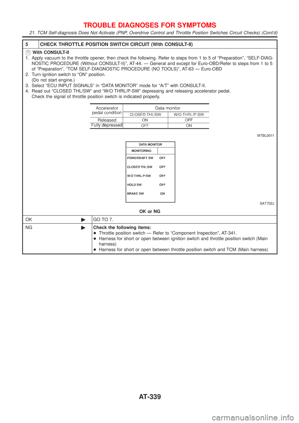
5 CHECK THROTTLE POSITION SWITCH CIRCUIT (With CONSULT-II)
With CONSULT-II
1. Apply vacuum to the throttle opener, then check the following. Refer to steps from 1 to 5 of ªPreparationº, ªSELF-DIAG-
NOSTIC PROCEDURE (Without CONSULT-II)º, AT-44. Ð General and except for Euro-OBD/Refer to steps from 1 to 5
of ªPreparationº, ªTCM SELF-DIAGNOSTIC PROCEDURE (NO TOOLS)º, AT-63 Ð Euro-OBD
2. Turn ignition switch to ªONº position.
(Do not start engine.)
3. Select ªECU INPUT SIGNALSº in ªDATA MONITORº mode for ªA/Tº with CONSULT-II.
4. Read out ªCLOSED THL/SWº and ªW/O THRL/P-SWº depressing and releasing accelerator pedal.
Check the signal of throttle position switch is indicated properly.
MTBL0011
SAT702J
OK or NG
OK©GO TO 7.
NG©Check the following items:
+Throttle position switch Ð Refer to ªComponent Inspectionº, AT-341.
+Harness for short or open between ignition switch and throttle position switch (Main
harness)
+Harness for short or open between throttle position switch and TCM (Main harness)
TROUBLE DIAGNOSES FOR SYMPTOMS
21. TCM Self-diagnosis Does Not Activate (PNP, Overdrive Control and Throttle Position Switches Circuit Checks) (Cont'd)
AT-339
Page 342 of 2898
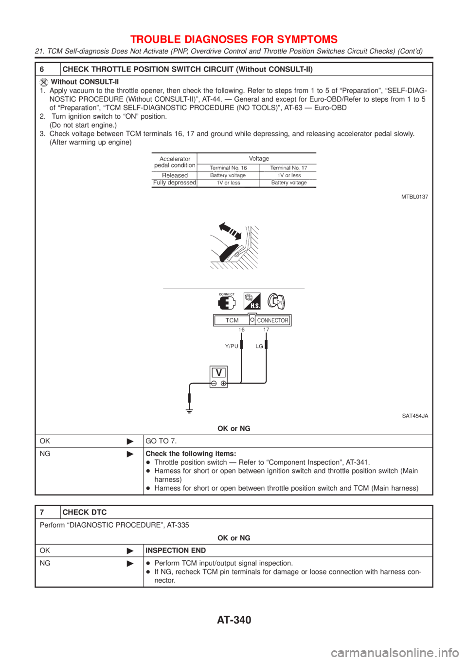
6 CHECK THROTTLE POSITION SWITCH CIRCUIT (Without CONSULT-II)
Without CONSULT-II
1. Apply vacuum to the throttle opener, then check the following. Refer to steps from 1 to 5 of ªPreparationº, ªSELF-DIAG-
NOSTIC PROCEDURE (Without CONSULT-II)º, AT-44. Ð General and except for Euro-OBD/Refer to steps from 1 to 5
of ªPreparationº, ªTCM SELF-DIAGNOSTIC PROCEDURE (NO TOOLS)º, AT-63 Ð Euro-OBD
2. Turn ignition switch to ªONº position.
(Do not start engine.)
3. Check voltage between TCM terminals 16, 17 and ground while depressing, and releasing accelerator pedal slowly.
(After warming up engine)
MTBL0137
SAT454JA
OK or NG
OK©GO TO 7.
NG©Check the following items:
+Throttle position switch Ð Refer to ªComponent Inspectionº, AT-341.
+Harness for short or open between ignition switch and throttle position switch (Main
harness)
+Harness for short or open between throttle position switch and TCM (Main harness)
7 CHECK DTC
Perform ªDIAGNOSTIC PROCEDUREº, AT-335
OK or NG
OK©INSPECTION END
NG©+Perform TCM input/output signal inspection.
+If NG, recheck TCM pin terminals for damage or loose connection with harness con-
nector.
TROUBLE DIAGNOSES FOR SYMPTOMS
21. TCM Self-diagnosis Does Not Activate (PNP, Overdrive Control and Throttle Position Switches Circuit Checks) (Cont'd)
AT-340
Page 343 of 2898
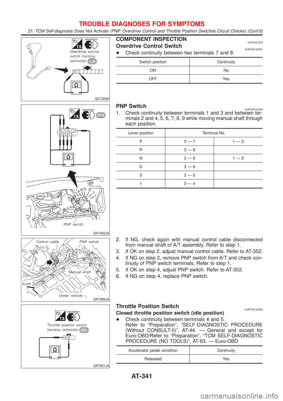
SAT005K
COMPONENT INSPECTIONNJAT0351S03Overdrive Control SwitchNJAT0351S0301+Check continuity between two terminals 7 and 8.
Switch position Continuity
ON No
OFF Yes
SAT402JA
PNP SwitchNJAT0351S03021. Check continuity between terminals 1 and 3 and between ter-
minals 2 and 4, 5, 6, 7, 8, 9 while moving manual shaft through
each position.
Lever position Terminal No.
P 3Ð7 1Ð2
R 3Ð8
N 3Ð9 1Ð2
D 3Ð6
2 3Ð5
1 3Ð4
SAT089JA
2. If NG, check again with manual control cable disconnected
from manual shaft of A/T assembly. Refer to step 1.
3. If OK on step 2, adjust manual control cable. Refer to AT-352.
4. If NG on step 2, remove PNP switch from A/T and check con-
tinuity of PNP switch terminals. Refer to step 1.
5. If OK on step 4, adjust PNP switch. Refer to AT-352.
6. If NG on step 4, replace PNP switch.
SAT851JA
Throttle Position SwitchNJAT0351S0303Closed throttle position switch (idle position)
+Check continuity between terminals 4 and 5.
Refer to ªPreparationº, ªSELF-DIAGNOSTIC PROCEDURE
(Without CONSULT-II)º, AT-44. Ð General and except for
Euro-OBD/Refer to ªPreparationº, ªTCM SELF-DIAGNOSTIC
PROCEDURE (NO TOOLS)º, AT-63. Ð Euro-OBD
Accelerator pedal condition Continuity
Released Yes
TROUBLE DIAGNOSES FOR SYMPTOMS
21. TCM Self-diagnosis Does Not Activate (PNP, Overdrive Control and Throttle Position Switches Circuit Checks) (Cont'd)
AT-341
Page 344 of 2898
Accelerator pedal condition Continuity
Depressed No
+To adjust closed throttle position switch, refer to EC-100,
ªBasic Inspectionº.
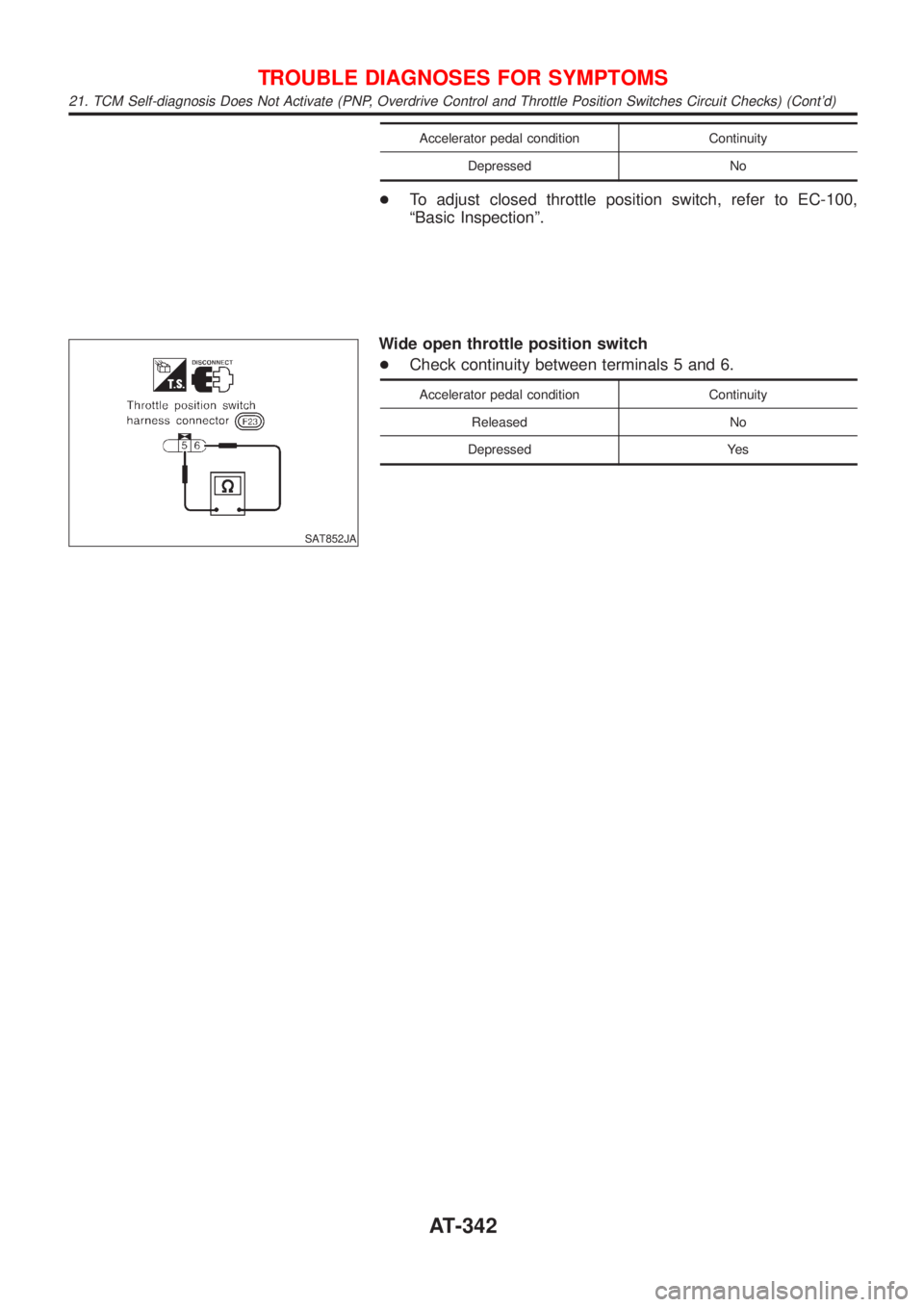
SAT852JA
Wide open throttle position switch
+Check continuity between terminals 5 and 6.
Accelerator pedal condition Continuity
Released No
Depressed Yes
TROUBLE DIAGNOSES FOR SYMPTOMS
21. TCM Self-diagnosis Does Not Activate (PNP, Overdrive Control and Throttle Position Switches Circuit Checks) (Cont'd)
AT-342
Page 345 of 2898
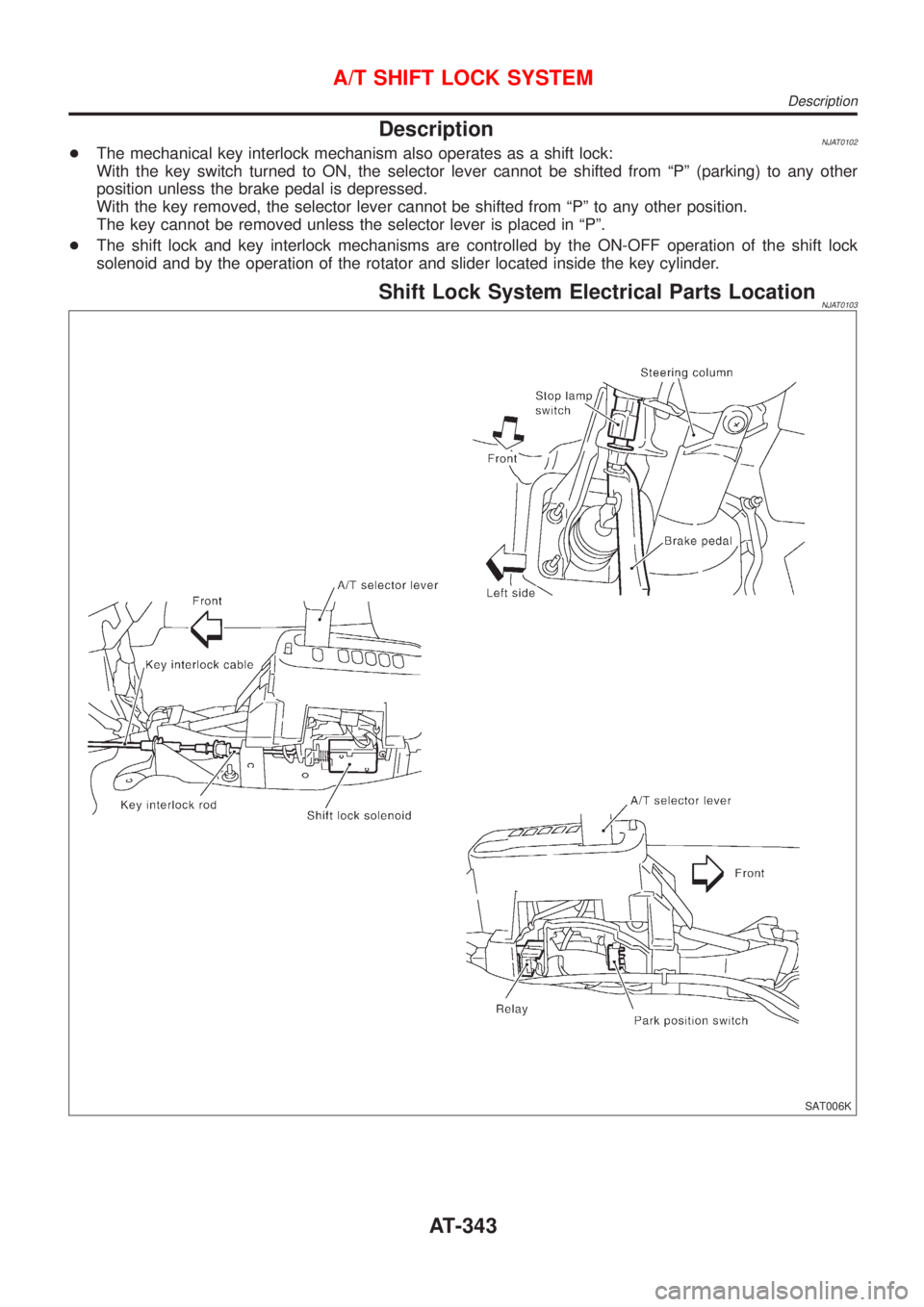
DescriptionNJAT0102+The mechanical key interlock mechanism also operates as a shift lock:
With the key switch turned to ON, the selector lever cannot be shifted from ªPº (parking) to any other
position unless the brake pedal is depressed.
With the key removed, the selector lever cannot be shifted from ªPº to any other position.
The key cannot be removed unless the selector lever is placed in ªPº.
+The shift lock and key interlock mechanisms are controlled by the ON-OFF operation of the shift lock
solenoid and by the operation of the rotator and slider located inside the key cylinder.
Shift Lock System Electrical Parts LocationNJAT0103
SAT006K
A/T SHIFT LOCK SYSTEM
Description
AT-343
Page 346 of 2898
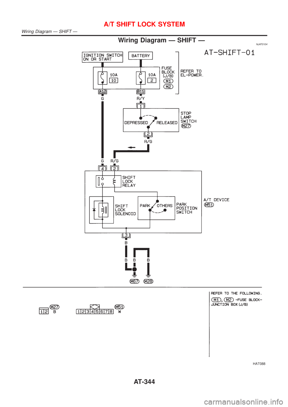
Wiring Diagram Ð SHIFT ÐNJAT0104
HAT088
A/T SHIFT LOCK SYSTEM
Wiring Diagram Ð SHIFT Ð
AT-344
Page 347 of 2898
Diagnostic ProcedureNJAT0105SYMPTOM 1:
+Selector lever cannot be moved from ªPº position with key
in ON position and brake pedal applied.
+Selector lever can be moved from ªPº position with key in
ON position and brake pedal released.
+Selector lever can be moved from ªPº position when key
is removed from key cylinder.
SYMPTOM 2:
Ignition key cannot be removed when selector lever is set to
ªPº position. It can be removed when selector lever is set to
any position except ªPº.
1 CHECK KEY INTERLOCK CABLE
Check key interlock cable for damage.
OK or NG
OK©GO TO 2.
NG©Repair key interlock cable. Refer to AT-349.
2 CHECK SELECTOR LEVER POSITION
Check selector lever position for damage.
OK or NG
OK©GO TO 3.
NG©Check selector lever. Refer to ªON-VEHICLE SERVICE Ð PNP Switch and Control
Cable Adjustmentº, AT-352.
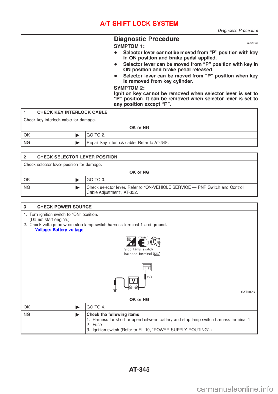
3 CHECK POWER SOURCE
1. Turn ignition switch to ªONº position.
(Do not start engine.)
2. Check voltage between stop lamp switch harness terminal 1 and ground.
Voltage: Battery voltage
SAT007K
OK or NG
OK©GO TO 4.
NG©Check the following items:
1. Harness for short or open between battery and stop lamp switch harness terminal 1
2. Fuse
3. Ignition switch (Refer to EL-10, ªPOWER SUPPLY ROUTINGº.)
A/T SHIFT LOCK SYSTEM
Diagnostic Procedure
AT-345
Page 348 of 2898
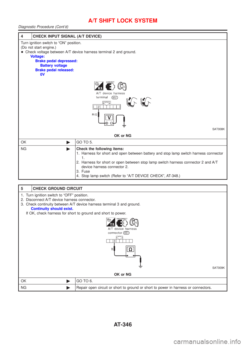
4 CHECK INPUT SIGNAL (A/T DEVICE)
Turn ignition switch to ªONº position.
(Do not start engine.)
+Check voltage between A/T device harness terminal 2 and ground.
Voltage:
Brake pedal depressed:
Battery voltage
Brake pedal released:
0V
SAT008K
OK or NG
OK©GO TO 5.
NG©Check the following items:
1. Harness for short and open between battery and stop lamp switch harness connector
1.
2. Harness for short or open between stop lamp switch harness connector 2 and A/T
device harness connector 2.
3. Fuse
4. Stop lamp switch (Refer to ªA/T DEVICE CHECKº, AT-348.)
5 CHECK GROUND CIRCUIT
1. Turn ignition switch to ªOFFº position.
2. Disconnect A/T device harness connector.
3. Check continuity between A/T device harness terminal 3 and ground.
Continuity should exist.
If OK, check harness for short to ground and short to power.
SAT009K
OK or NG
OK©GO TO 6.
NG©Repair open circuit or short to ground or short to power in harness or connectors.
A/T SHIFT LOCK SYSTEM
Diagnostic Procedure (Cont'd)
AT-346
Page 349 of 2898
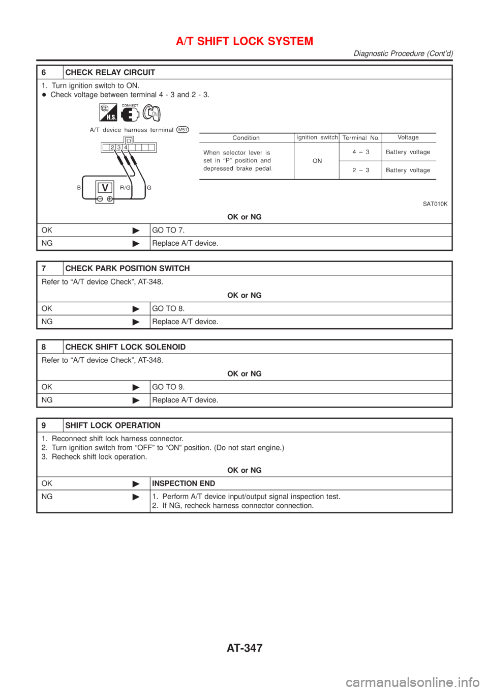
6 CHECK RELAY CIRCUIT
1. Turn ignition switch to ON.
+Check voltage between terminal4-3and2-3.
SAT010K
OK or NG
OK©GO TO 7.
NG©Replace A/T device.
7 CHECK PARK POSITION SWITCH
Refer to ªA/T device Checkº, AT-348.
OK or NG
OK©GO TO 8.
NG©Replace A/T device.
8 CHECK SHIFT LOCK SOLENOID
Refer to ªA/T device Checkº, AT-348.
OK or NG
OK©GO TO 9.
NG©Replace A/T device.
9 SHIFT LOCK OPERATION
1. Reconnect shift lock harness connector.
2. Turn ignition switch from ªOFFº to ªONº position. (Do not start engine.)
3. Recheck shift lock operation.
OK or NG
OK©INSPECTION END
NG©1. Perform A/T device input/output signal inspection test.
2. If NG, recheck harness connector connection.
A/T SHIFT LOCK SYSTEM
Diagnostic Procedure (Cont'd)
AT-347
Page 350 of 2898
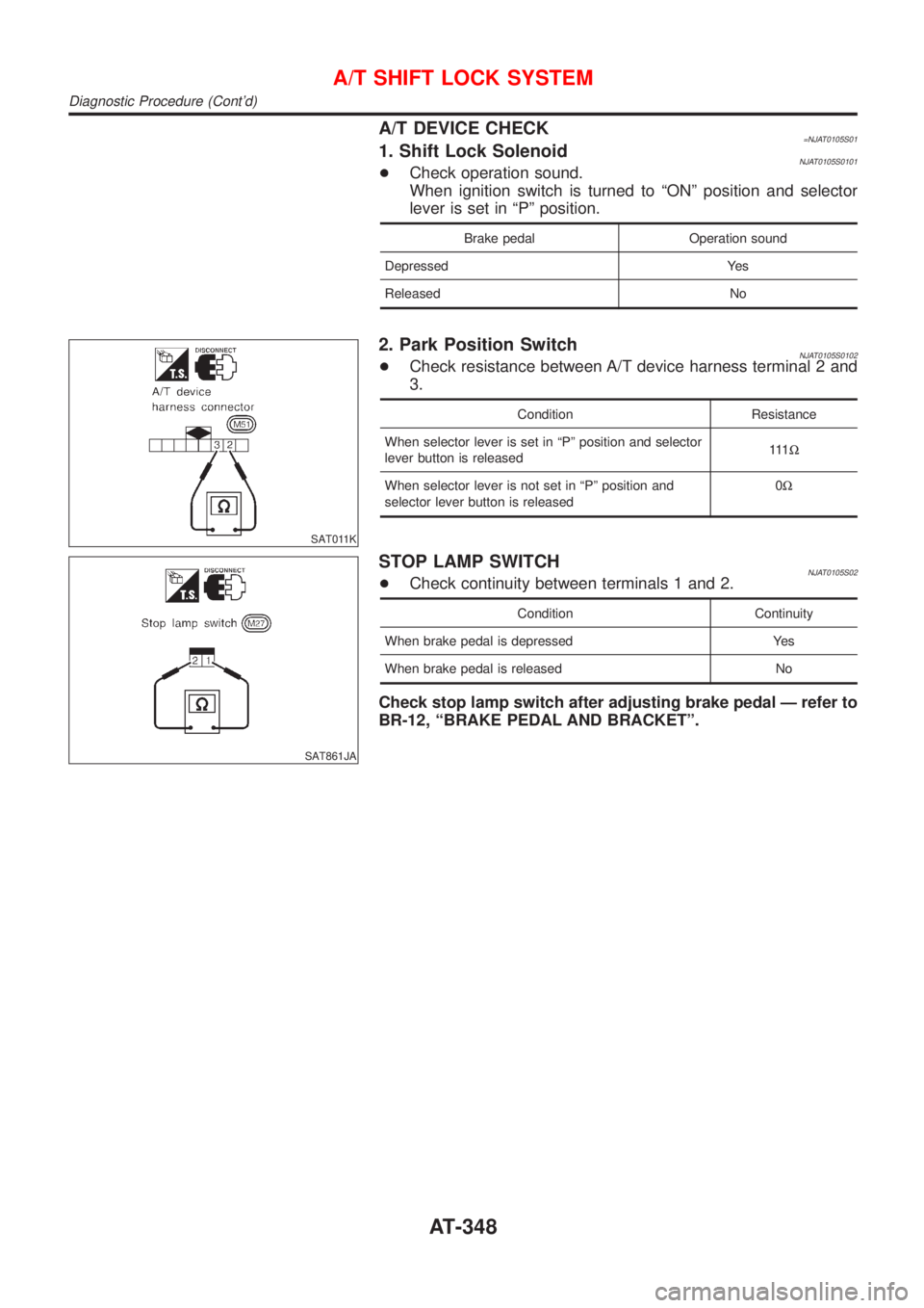
A/T DEVICE CHECK=NJAT0105S011. Shift Lock SolenoidNJAT0105S0101+Check operation sound.
When ignition switch is turned to ªONº position and selector
lever is set in ªPº position.
Brake pedal Operation sound
Depressed Yes
Released No
SAT011K
2. Park Position SwitchNJAT0105S0102+Check resistance between A/T device harness terminal 2 and
3.
Condition Resistance
When selector lever is set in ªPº position and selector
lever button is released111W
When selector lever is not set in ªPº position and
selector lever button is released0W
SAT861JA
STOP LAMP SWITCHNJAT0105S02+Check continuity between terminals 1 and 2.
Condition Continuity
When brake pedal is depressed Yes
When brake pedal is released No
Check stop lamp switch after adjusting brake pedal Ð refer to
BR-12, ªBRAKE PEDAL AND BRACKETº.
A/T SHIFT LOCK SYSTEM
Diagnostic Procedure (Cont'd)
AT-348