NISSAN ALMERA N15 1995 Service Manual
Manufacturer: NISSAN, Model Year: 1995, Model line: ALMERA N15, Model: NISSAN ALMERA N15 1995Pages: 1701, PDF Size: 82.27 MB
Page 1091 of 1701
VE-TVPEINJECTION PUMP
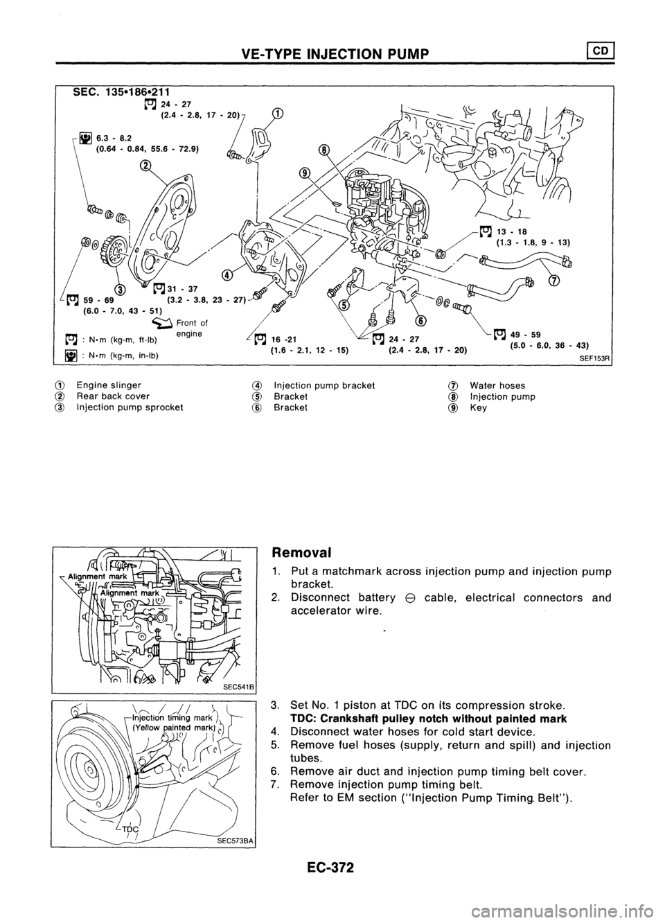
G)
Engine slinger
@
Rear backcover
@
Injection pumpsprocket
@
Injection pumpbracket
@
Bracket
@
Bracket
(J)
Water hoses
@
Injection pump
@ Key
Removal
1. Put amatchmark acrossinjection pumpandinjection pump
bracket.
2. Disconnect battery
e
cable, electrical connectors and
accelerator wire.
3. Set No.1 piston atTDe onitscompression stroke.
TOC: Crankshaft pulleynotchwithout painted mark
4. Disconnect waterhoses forcold start device.
5. Remove fuelhoses (supply, returnandspill) andinjection
tubes.
6. Remove airduct andinjection pumptiming beltcover.
7. Remove injection pumptiming belt.
Refer toEM section ("Injection PumpTiming. Belt").
EC-372
Page 1092 of 1701
VE-TVPEINJECTION PUMP ~
Removal (Cont'd)
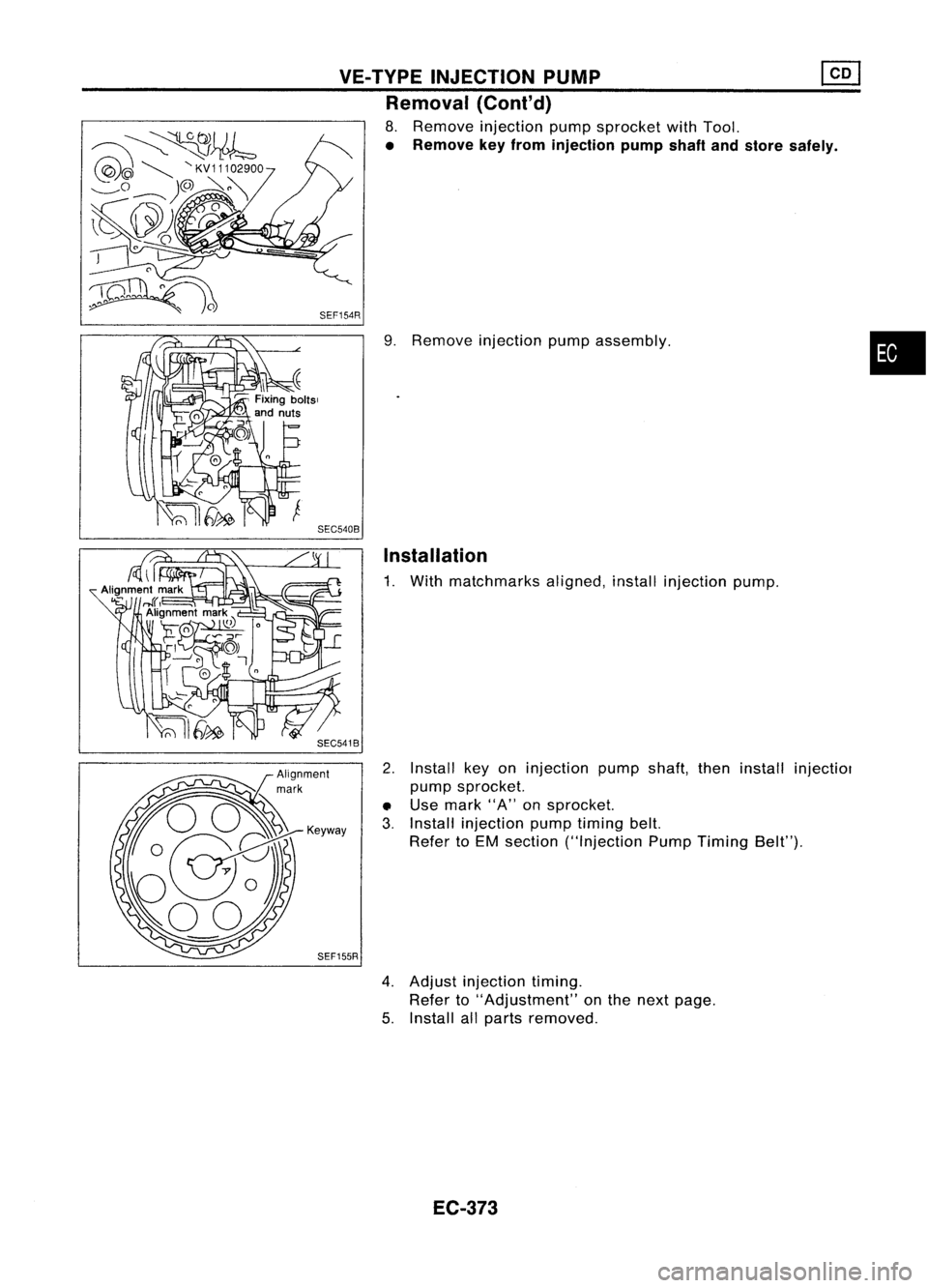
8. Remove injection pumpsprocket withTool.
• Remove keyfrom injection pumpshaftandstore safely .
9. Remove injection pumpassembly.
Installation
1. With matchmarks aligned,installinjection pump.
2. Install keyoninjection pumpshaft,theninstall injectiol
pump sprocket.
• Use mark "A"onsprocket.
3. Install injection pumptiming belt.
Refer toEM section ("Injection PumpTiming Belt").
SEF155R
4.Adjust injection timing.
Refer to"Adjustment" onthe next page.
5. Install allparts removed.
EC-373
•
Page 1093 of 1701
VE-TYPE INJECTION PUMP
SEF779A
Adjustment
INJECTION TIMINGADJUSTMENT (Plunger
lift
adjustment)
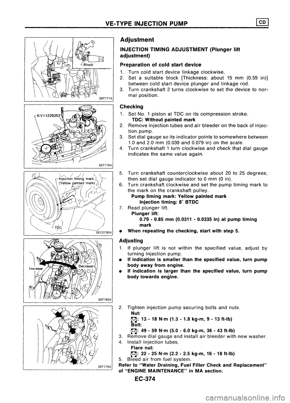
Preparation ofcold start device
1. Turn coldstart device linkage clockwise.
2. Set asuitable block[Thickness: about15mm (0.59 in)]
between coldstart device plunger andlinkage rod.
3. Turn crankshaft 2turns clockwise toset the device tonor-
mal position.
Checking
1. Set NO.1 piston atTDC onitscompression stroke.
TDC: Without paintedmark
2. Remove injection tubesandairbleeder onthe back ofinjec-
tion pump.
3. Set dial gauge soitsindicator pointstosomewhere between
1.0 and 2.0mm (0.039 and0.079 in)onthe scale.
4. Turn crankshaft 1turn clockwise andcheck thatdialgauge
indicates thesame value again.
5. Turn crankshaft counterclockwise about20to25 degrees,
then setdial gauge indicator to0mm (0in).
6. Turn crankshaft clockwiseandsetthe pump timing markto
the mark onthe crankshaft pulley.
Pump timing mark:Yellow painted mark
Injection timing:8
0
BTDC
7. Read plunger lift.
Plunger lift:
0.79 -0.85 mm(0.0311 -0.0335 in)atpump timing
mark
• When repeating thechecking, startwithstep 5.
Adjusting
1. Ifplunger liftisnot within thespecified value,adjust by
turning injection pump.
• Ifindication issmaller thanthespecified value,turnpump
body away fromengine.
• Ifindication islarger thanthespecified value,turnpump
body towards engine.
2. Tighten injection pumpsecuring boltsandnuts.
Nut:
~: 13-18 N.m (1.3-1.8 kg-m, 9-13 ft-Ib)
Bolt:
~: 49-59 N.m (5.0-6.0 kg-m, 36-43 ft-Ib)
3. Remove dialgauge andinstall airbleeder withnewwasher.
4. Install injection tubes.
Flare nut:
~: 22-25 N.m (2.2-2.5 kg-m, 16-18 ft-Ib)
5. Bleed airfrom fuelsystem.
Refer to"Water Draining, FuelFilter Check andReplacement"
of "ENGINE MAINTENANCE" inMA section.
EC-374
Page 1094 of 1701
VE-TVPEINJECTION PUMP ~
Adjustment (Cont'd)
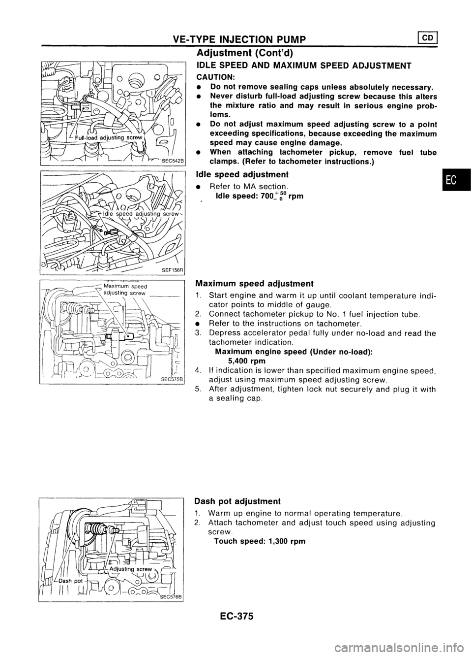
IDLE SPEED ANDMAXIMUM SPEEDADJUSTMENT
CAUTION:
• Donot remove sealingcapsunless absolutely necessary.
• Never disturb full-load adjusting screwbecause thisalters
the mixture ratioandmay result inserious engineprob-
lems.
• Donot adjust maximum speedadjusting screwtoapoint
exceeding specifications, becauseexceeding themaximum
speed maycause engine damage.
• When attaching tachometer pickup,remove fueltUbe
clamps. (Refertotachometer instructions.)
Idle speed adjustment •
• Refer toMA section.
Idle speed:
700~
~o
rpm
SEF156R Maximum speedadjustment
1. Start engine andwarm itup until coolant temperature indi-
cator points tomiddle ofgauge.
2. Connect tachometer pickuptoNO.1 fuelinjection tube.
• Refer tothe instructions ontachometer.
3. Depress accelerator pedalfullyunder no-load andread the
tachometer indication.
Maximum enginespeed(Under no-load):
5,400 rpm
4.
If
indication islower thanspecified maximum enginespeed,
adjust usingmaximum speedadjusting screw.
5. After adjustment, tightenlocknutsecurely andplug itwith
a sealing cap.
Dash potadjustment
1. Warm upengine tonormal operating temperature.
2. Attach tachometer andadjust touchspeed usingadjusting
screw.
Touch speed: 1,300rpm
EC-375
Page 1095 of 1701
Nozzleside
Combustion
chamber side
SEF668A
SEF781A
SEF669A
:S
older ~Adiusting shim
c:,
Nozzlespring
~ '~[;{~I:,""'
pi,",
Nozzle needle~~(''''-
Nozzle bOdyr ~
Nozzle nut)
SEF670A INJECTION
NOZZLE
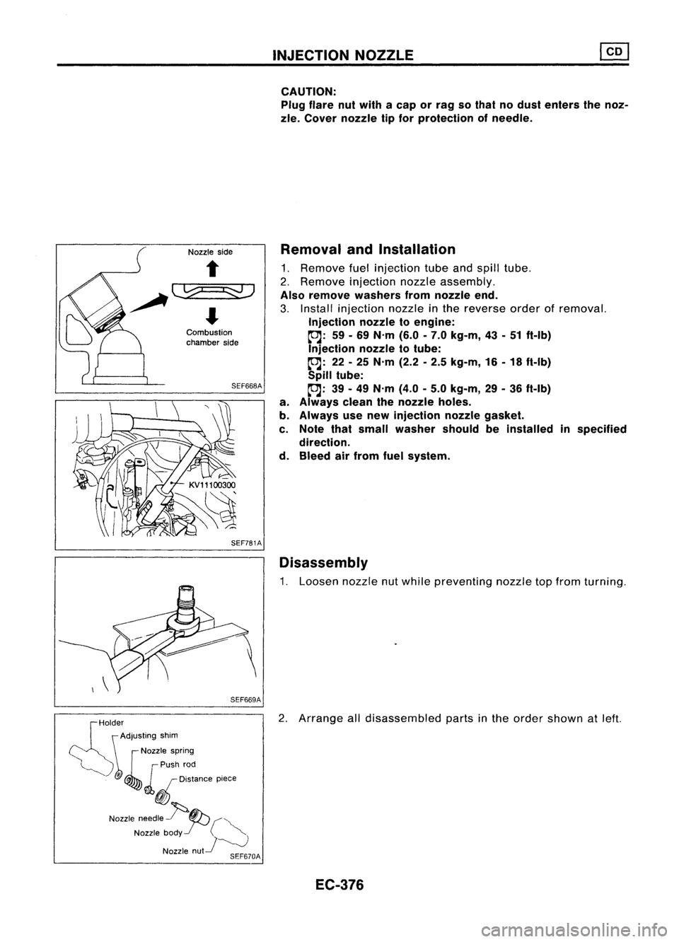
CAUTION: Plug flare nutwith acap orrag sothat nodust enters thenoz-
zle. Cover nozzle tipfor protection ofneedle.
Removal andInstallation
1. Remove fuelinjection tubeandspill tube.
2. Remove injection nozzleassembly.
Also remove washers fromnozzle end.
3. Install injection nozzleinthe reverse orderofremoval.
Injection nozzletoengine:
~: 59-69 N'm (6.0-7.0 kg-m, 43-51 ft-Ib)
Injection nozzletotube:
~: 22-25 N'm (2.2-2.5 kg-m, 16-18 ft-Ib)
Spill tube:
~: 39-49 N'm (4.0-5.0 kg-m, 29-36 ft-Ib)
a. Always cleanthenozzle holes.
b. Always usenew injection nozzlegasket.
c. Note thatsmall washer shouldbeinstalled inspecified
direction.
d. Bleed airfrom fuelsystem.
Disassembly
1. Loosen nozzlenutwhile preventing nozzletopfrom turning.
2. Arrange alldisassembled partsinthe order shown atleft.
EC-376
Page 1096 of 1701
SEF830INJECTION
NOZZLE
Inspection
Thoroughly cleanalldisassembled partswithfresh kerosene or
solvent.
• Ifnozzle needle isdamaged orfused, replace nozzle
assembly withanew one.
• Ifend ofnozzle needle isseized orexcessively discolored,
replace nozzleassembly.
• Check nozzle bodyanddistance pieceforproper contact. If
excessively wornordamaged, replacenozzleassembly or
distance piece.
• Check distance pieceandnozzle holderforproper contact.
If
excessively wornordamaged, replacedistance pieceor•
nozzle holder.
• Check nozzle springforexcessive wearordamage. If
excessively wornordamaged, replaceitwith anew spring.
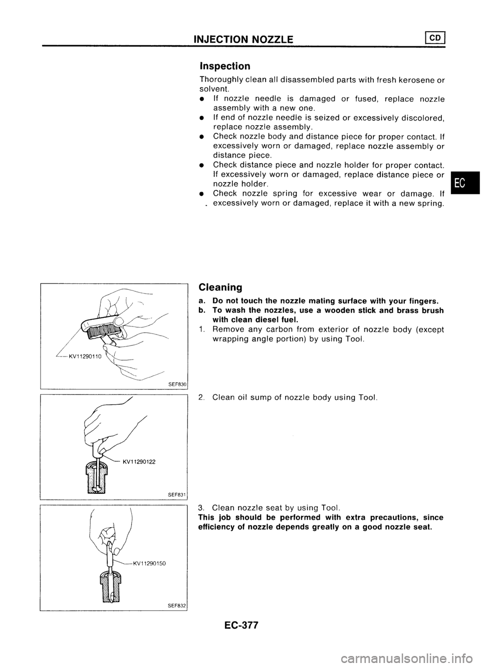
Cleaning
a. Donot touch thenozzle mating surface withyour fingers.
b. Towash thenozzles, useawooden stickandbrass brush
with clean diesel fuel.
1. Remove anycarbon fromexterior ofnozzle body(except
wrapping angleportion) byusing Tool.
2. Clean oilsump ofnozzle bodyusing Tool.
KV11290150 SEF831
SEF832
3.
Clean nozzle seatbyusing Tool.
This jobshould beperformed withextra precautions, since
efficiency ofnozzle depends greatlyonagood nozzle seat.
EC-377
Page 1097 of 1701
KV11290220SEF833
SEF834
SEF835 INJECTION
NOZZLE ~
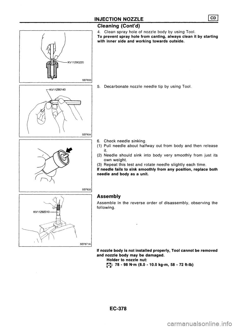
Cleaning (Coni'd)
4. Clean sprayholeofnozzle bodybyusing Tool.
To prevent sprayholefrom canting, alwayscleanitby starting
with inner sideandworking towardsoutside.
5. Decarbonate nozzleneedle tipbyusing Tool.
6. Check needle sinking.
(1) Pull needle abouthalfway outfrom body andthen release
it.
(2) Needle shouldsinkintobody verysmoothly fromjustits
own weight.
(3) Repeat thistestand rotate needle slightly eachtime.
If
needle failstosink smoothly fromanyposition, replaceboth
needle andbody asaunit.
KV11292010 SEF671AAssembly
Assemble inthe reverse orderofdisassembly, observingthe
following.
If
nozzle bodyisnot installed properly, Toolcannot beremoved
and nozzle bodymaybedamaged.
Holder tonozzle nut:
(OJ:
78-98 N'm (8.0-10.0 kg-m, 58-72 ft-Ib)
EC-378
Page 1098 of 1701
EF791AINJECTION
NOZZLE
Test andAdjustment
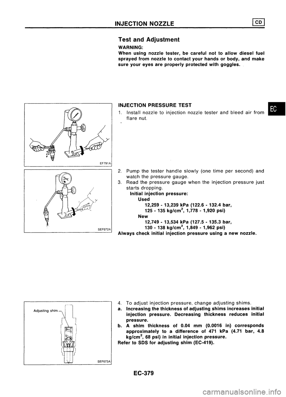
WARNING:
When usingnozzle tester,becareful nottoallow diesel fuel
sprayed fromnozzle tocontact yourhands orbody, andmake
sure your eyes areproperly protected withgoggles .
INJECTION PRESSURE TEST
1. Install nozzle toinjection nozzletesterandbleed airfrom
flare nut.
•
SEF672A
2.
Pump thetester handle slowly(onetime persecond) and
watch thepressure gauge.
3. Read thepressure gaugewhentheinjection pressure just
starts dropping.
Initial injection pressure:
Used 12,259 -13,239 kPa(122.6 -132.4 bar,
125 -135 kg/cm
2,
1,778•1,920 psi)
New 12,749 -13,534 kPa(127.5 -135.3 bar,
130 -138 kg/cm
2,
1,849•1,962 psi)
Always checkinitialinjection pressure usinganew nozzle.
Adjusting shim
SEF673A
4.
Toadjust injection pressure, changeadjusting shims.
a. Increasing thethickness ofadjusting shimsincreases initial
injection pressure. Decreasing thicknessreducesinitial
pressure.
b. Ashim thickness of0.04 mm(0.0016 in)corresponds
approximately toadifference of471 kPa (4.71 bar,4.8
kg/cm
2,
68psi) ininitial injection pressure.
Refer toSDS foradjusting shim(EC-419).
EC-379
Page 1099 of 1701
INJECTIONNOZZLE ~
Test andAdjustment (Cont'd)
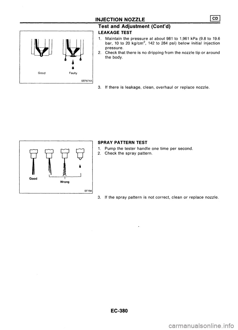
LEAKAGE TEST
1. Maintain thepressure atabout 981to1,961 kPa(9.8to19.6
bar, 10to20 kg/cm
2,
142to284 psi) below initialinjection
pressure.
2. Check thatthere isno dripping fromthenozzle tiporaround
the body.
Good
Faulty
SEF674A
3.Ifthere isleakage, clean,overhaul orreplace nozzle.
Good
I
Wrong
•
EF794 SPRAY
PATTERN TEST
1. Pump thetester handle onetime persecond.
2. Check thespray pattern .
3. Ifthe spray pattern isnot correct, cleanorreplace nozzle.
EC-380
Page 1100 of 1701
FUELSYSTEM CHECK
2. Check fuelcutsolenoid valveforcircuit continuity.
3. Remove fuelcutsolenoid valveandcheck thatplunger
moves smoothly andthat spring isnormal.
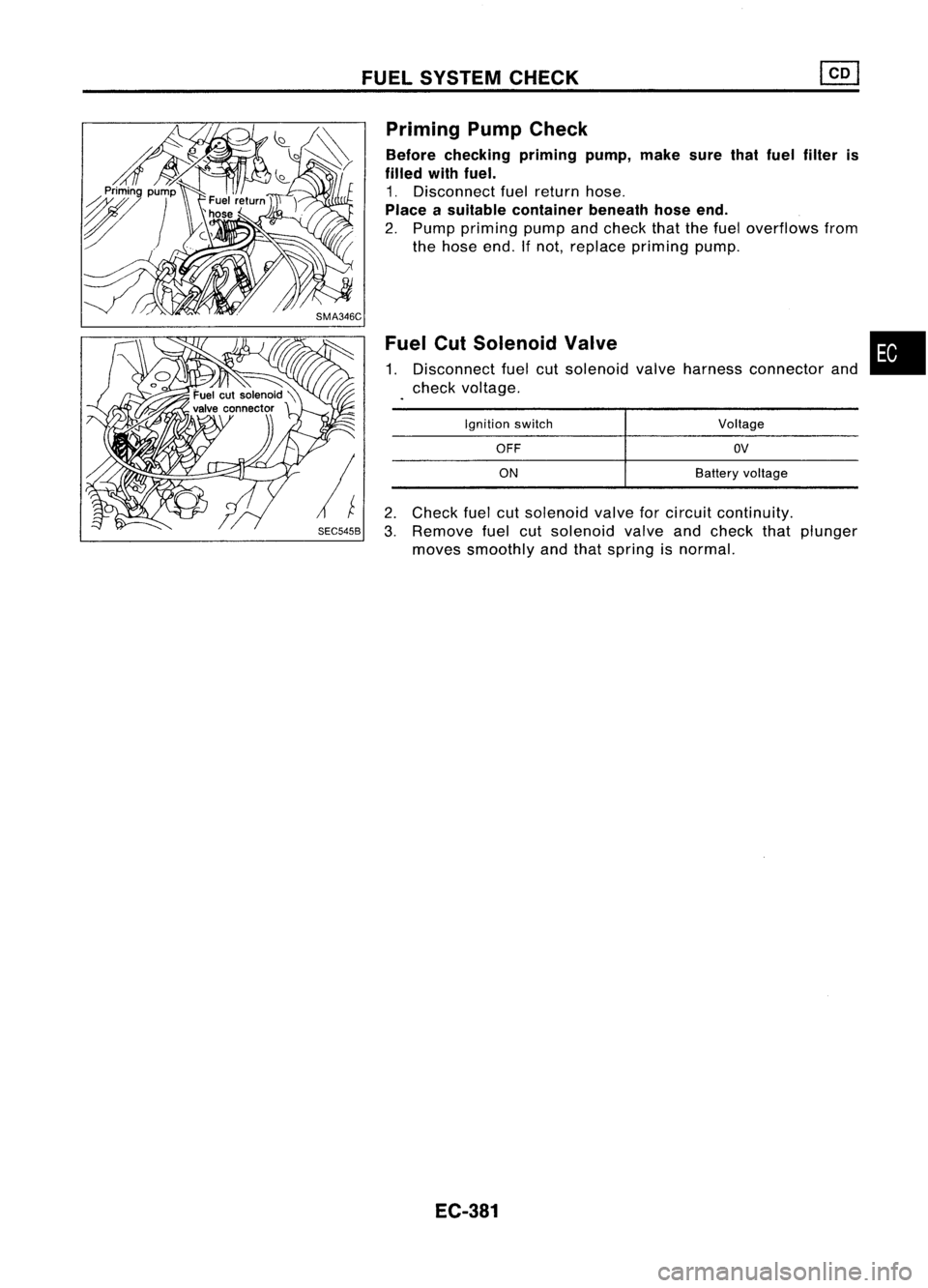
Fuel
CutSolenoid Valve
1. Disconnect fuelcutsolenoid valveharness connector and
check voltage.
Priming
PumpCheck
Before checking primingpump,makesurethatfuel filter is
filled withfuel.
1. Disconnect fuelreturn hose.
Place asuitable container beneathhoseend.
2. Pump priming pumpandcheck thatthefuel overflows from
the hose end.Ifnot, replace priming pump.
•
Voltage
OV
Battery voltage
OFF
ON
Ignition
switch
EC-381