NISSAN ALMERA N15 1995 Service Manual
Manufacturer: NISSAN, Model Year: 1995, Model line: ALMERA N15, Model: NISSAN ALMERA N15 1995Pages: 1701, PDF Size: 82.27 MB
Page 1061 of 1701
~i5
cf0
TROUBLE
DIAGNOSIS FORNON-DETECTABLE ITEMS
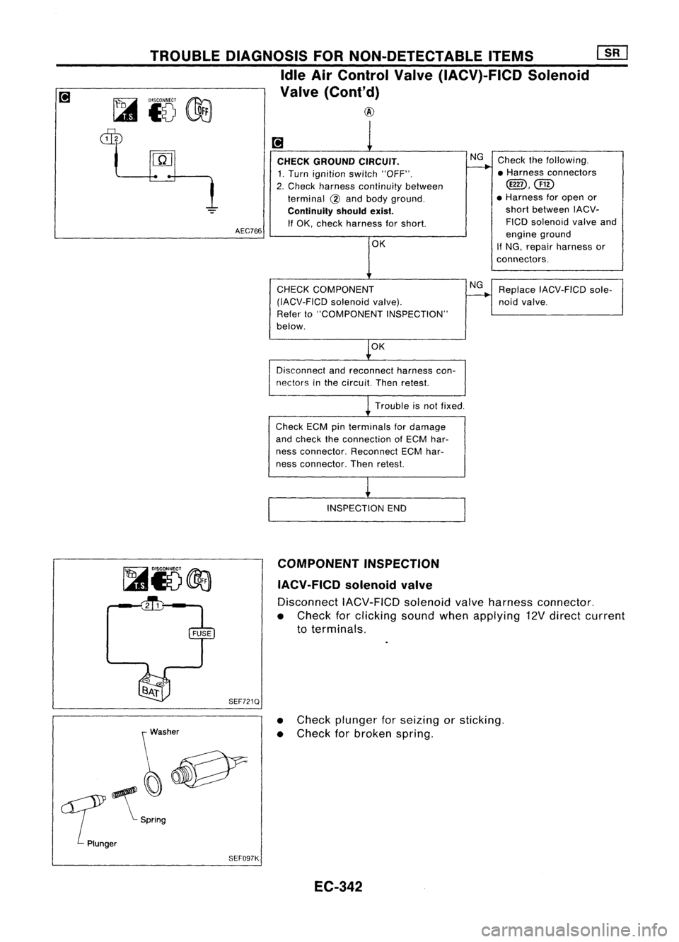
Idle AirControl Valve(IACV)-FICD Solenoid
Valve (Cont'd)
@
AEC766 CHECK
GROUND CIRCUIT.
1. Turn ignition switch"OFF".
2. Check harness continuity between
terminal
@
and body ground.
Continuity shouldexist.
If OK, check harness forshort.
OK
CHECK COMPONENT
(IACV-FICD solenoidvalve).
Refer to"COMPONENT INSPECTION"
below.
OK
Disconnect andreconnect harnesscon-
nectors inthe circuit. Thenretest.
Trouble isnot fixed.
Check ECMpinterminals fordamage
and check theconnection ofECM har-
ness connector. ReconnectECMhar-
ness connector. Thenretest.
INSPECTION END
NG
NG
Check
thefollowing.
• Harness connectors
cmD,@
• Harness foropen or
short between IACV-
FICO solenoid valveand
engine ground
If NG, repair harness or
connectors.
Replace IACV-FICD sole-
noid valve.
~i5@d
~
SEF721Q
\ Washer
~~v
err
~S~log
Plunger SEF097K:COMPONENT
INSPECTION
IACV-FICD solenoidvalve
Disconnect IACV-F1CDsolenoidvalveharness connector.
• Check forclicking soundwhenapplying 12Vdirect current
to terminals.
• Check plunger forseizing orsticking.
• Check forbroken spring.
EC-342
Page 1062 of 1701
TROUBLEDIAGNOSIS FORNON-DETECTABLE ITEMS
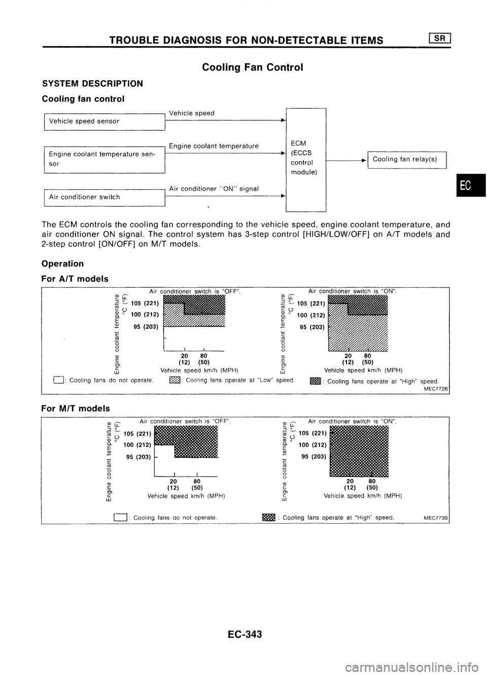
Cooling FanControl
SYSTEM DESCRIPTION
Cooling fancontrol
I
Vehicle speedsensor
I
Vehicle speed
Engine coolant temperature EGM
Engine coolant temperature sen- (EGGS
~
sor control
module)
I
Air conditioner switch
I
Air conditio~er "ON"signal
I
Goaling fanrelay(s)
•
The ECM controls thecooling fancorresponding tothe vehicle speed,engine coolant temperature, and
air conditioner ONsignal. Thecontrol system has3-step control [HIGH/LOW/OFF] onA/T models and
2-step control [ON/OFF] onM/T models.
Operation
For AIT models
Airconditioner switchis"ON".
20 80
(12) (50)
Vehicle speedkm/h(MPH)
m!lll:
Cooling fansoperate at"High" speed.
MEC772B
~u:
~ ?-
105 (221)
~ 0
2i
0
100 (212)
E
2
95(203)
C
'"
o
o
o
20 80
OJ
(12) (50) .~
Vehicle speedkm/h(MPH) ~
~: Cooling fansoperate at"Low" speed.
~LL
.3
?-
105 (221)
~o
2i
0
100 (212)
E
2
95(203)
C
'"
o
o
o
OJ
c:
.0,
c
w
0:
Cooling fansdonot operate.
For MIT models
Airconditioner switchis"OFF".
2080
(12) (50)
Vehicle speedkm/h(MPH)
~
u:
Airconditioner switchis"ON".
::J
0
1il
Z;
105 (221)
OJ
0
E
100(212)
OJ
- 95(203)
C
'"
o
o
o
OJ
c
0,
c
ill
I
20 80
(12) (50)
Vehicle speedkm/h(MPH)
~u:
::J
0
1il ;-
105 (221)
OJ
0
~ 100(212)
<1>
- 95(203)
C
'"
o
o
o
OJ
c
.0,
c
ill
0:
COOling fansdonot operate. m
:Cooling fansoperate at"High" speed.
MEC773B
EC-343
Page 1063 of 1701
TROUBLEDIAGNOSIS FORNON-DETECTABLE ITEMS~
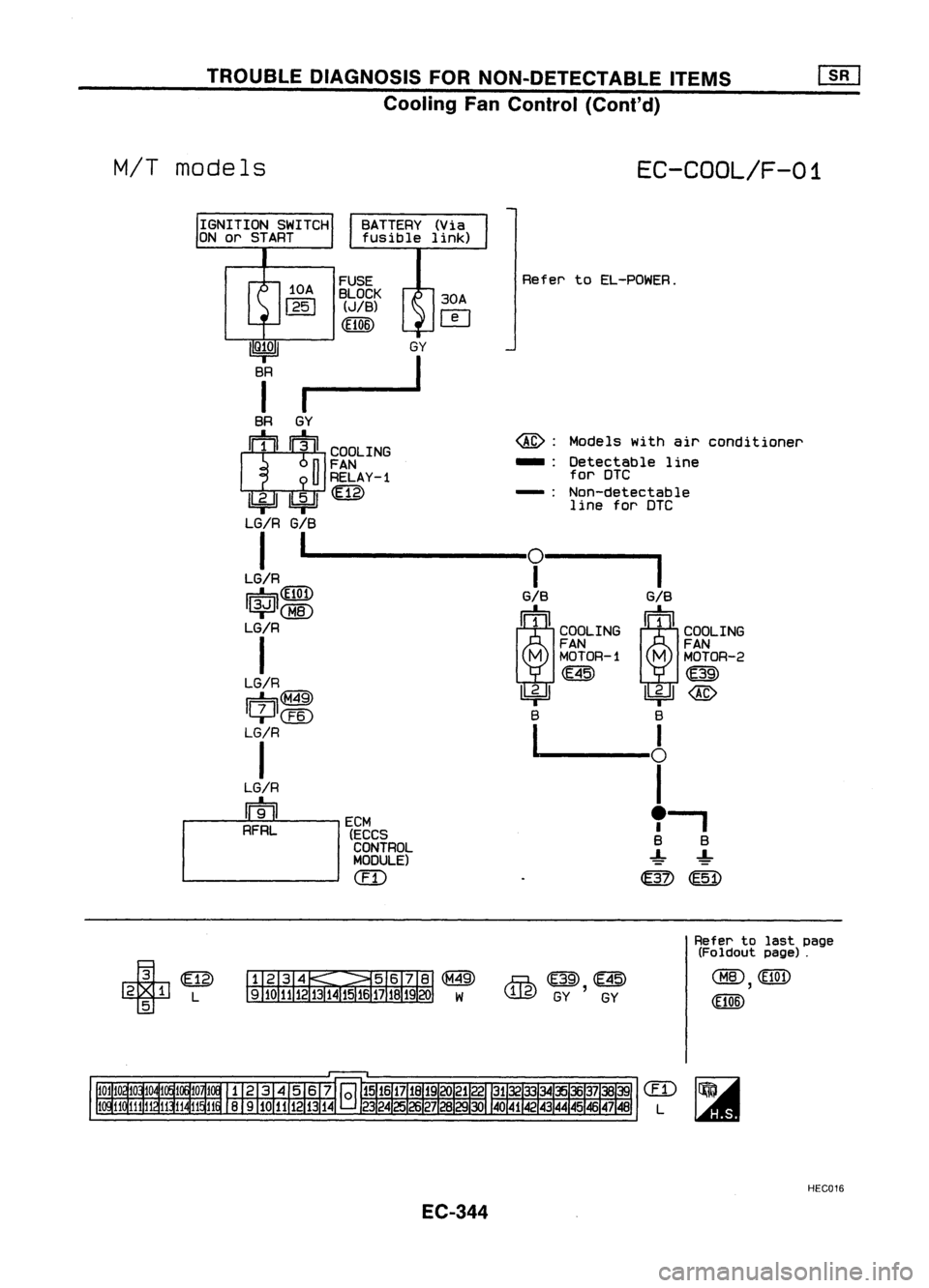
Cooling FanControl (Cont'd)
BATTERY (Via
fusible link)
M/T
models
FUSE
BLOCK
(JIB)
(El06) 30A
o
EC-COOL/F-01
Refer toEL-POWER.
@:
Models withairconditioner
... :Detectable line
for DIC
-: Non-detectable
line forOle
IIQ~OI
GY
BR
I
I
1--
BR GY
II!
]11
COOLING
n
FAN
u
RELAY-1
1biJ1bi=Jl@
LG/R
G/B
I
1----
0--
1
LG/R
I
r=::!=
I~I(][)
mm
LG/R ~COOLING ~COOLING
I
FANFAN
M
MOTOR-l
M
MOTOR-2
LG/R (E45)
rn
II-t-JI(M49) ~~
@
+@
BB
LrR
l-------6
LG/R
I
m
e.
1
- I
ECM
RFRL
(ECCS BB
CONTROL
..L_..L_
MODULE)
------ em
ern>
@D
+
2 1 L
5
~@~
lJ.l.g)
GY,GY
Refer
tolast page
(Foldout page).
@
(El0t)
,
(El06)
EC-344
em
L
HEC016
Page 1064 of 1701
![NISSAN ALMERA N15 1995 Service Manual TROUBLEDIAGNOSIS FORNON-DETECTABLE ITEMS[][]
Cooling FanControl (Cont'd)
•
t
t
EC-COOL/F-02
COOLING
FAN
MOTOR-2
rn
@
tt
@:
Models withair
conditioner
... :Detectable line
for DTC
-: N NISSAN ALMERA N15 1995 Service Manual TROUBLEDIAGNOSIS FORNON-DETECTABLE ITEMS[][]
Cooling FanControl (Cont'd)
•
t
t
EC-COOL/F-02
COOLING
FAN
MOTOR-2
rn
@
tt
@:
Models withair
conditioner
... :Detectable line
for DTC
-: N](/img/5/57349/w960_57349-1063.png)
TROUBLEDIAGNOSIS FORNON-DETECTABLE ITEMS[][]
Cooling FanControl (Cont'd)
•
t
t
EC-COOL/F-02
COOLING
FAN
MOTOR-2
rn
@
tt
@:
Models withair
conditioner
... :Detectable line
for DTC
-: Non-detectable
line forDTC
____ r~-,
S S
-!- -!-
~
Refer
to
EL-POWEA.
ECM (ECCS
CONTROL
MODULE)
(IT)
i0A
FUSE
~.jffil
I
25
I
~~9~f
30A30A
(El06)
IT]
IT]
GY G/W
• --1
-~-,-I-FO~=-_I
I
SR GYG/W SRGYLG/S SAG/WLG/R
COOLINGII:!:I :!i':]JII COOLINGI':}:' ':f]1I:[]II COOLING/I:!:I 1:f]1':[]II
~~~AY-i ~~~~~AY-2 ~~~~~AY-3 ~~
(ffi) ~~ ~
rn ~
lbiJ
U+!J
~iC8) ~
lbiJ~
LG/R G/8G/A LGG/Y 8
@
LGG/OR S
I~ -
-tr=-
!-.J
_I _
I--~
LG ~LG/R
I
r:::::k,{jQj;r:::::k,
114.J
I~---
-l13.J
II
G/R
LG ~LG/R
wT1
I I
~~~LING~)
MOTOR-1
LG (M49) LG/R ~
1t!J~
-F6-
~cPl
LG
CEID
LG/R
I ~
1~
LG LG/R
rrToi1
rm
AFAH RFRL
AIT
models
IGNITION SWITCH
ON
or
STAAT
~ (Ei2),(Ei7),(Ei8)
~ SRSRSR ~
(E40),(E46)
t::mJ
GYGY
Refer
tolast page
(Foldout page).
~ (El0!)
,
(El06)
em
L
HEC017
EC-345
Page 1065 of 1701
TROUBLEDIAGNOSIS FORNON-DETECTABLE ITEMS
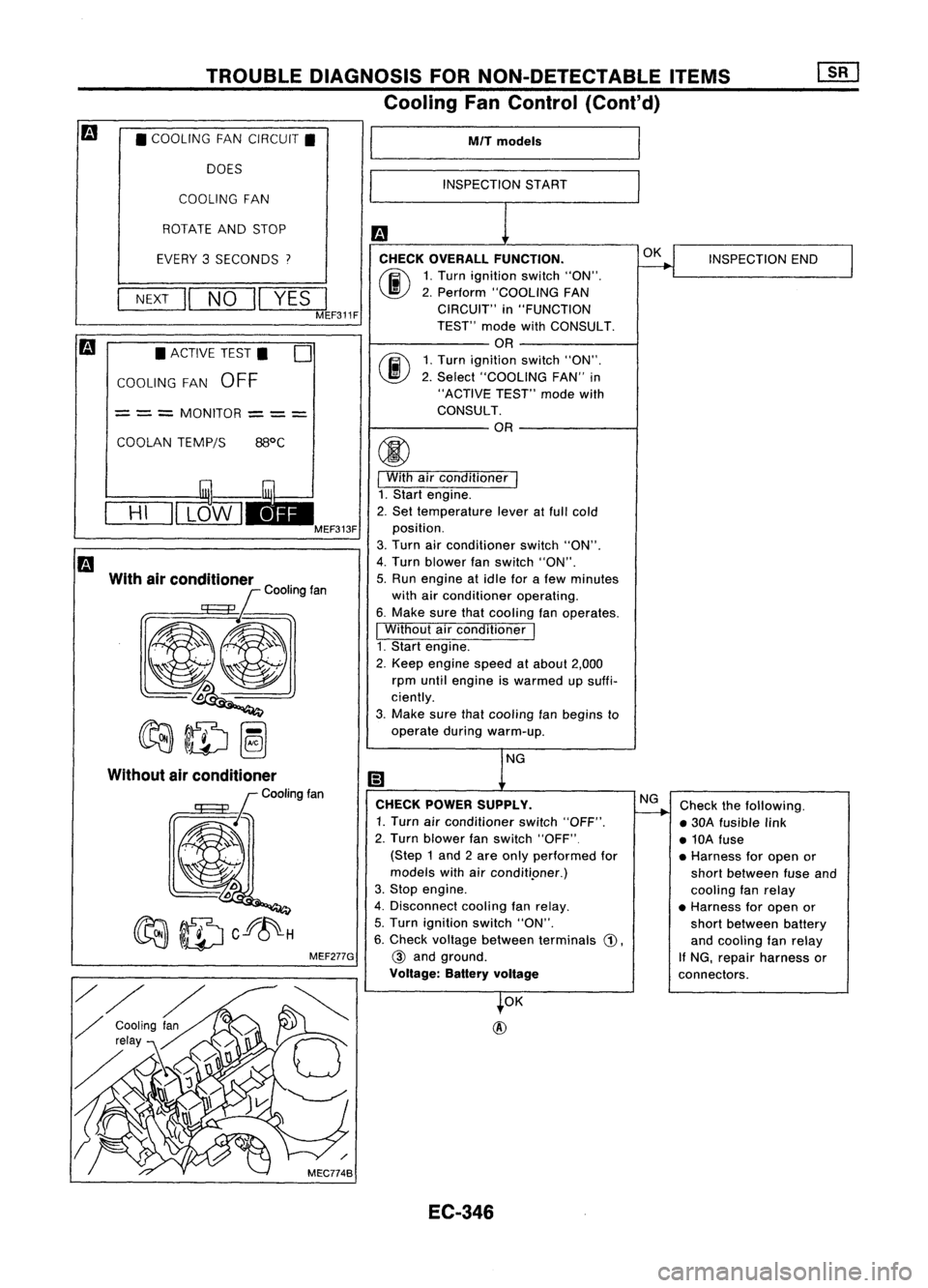
Cooling FanControl (Cont'd)
• COOLING FANCIRCUIT.
DOES
COOLING FAN
ROTATE ANDSTOP
EVERY 3SECONDS
7
NEXT
II
NO
II
YES
I
MEF311F
• ACTIVE TEST.
0
COOLING FAN
OFF
= ==
MONITOR
==
=
COOLAN TEMP/S
HI
With airconditioner
C
k
00lin9fan
Q
~ID~
MEF277G
M/T
models
INSPECTION START
CHECK OVERALL FUNCTION.
(ij\
1.Turn ignition switch"ON".
~ 2.Perform "COOLING FAN
CIRCUIT" in"FUNCTION
TEST" modewithCONSULT.
OR
rij\
1.Turn ignition switch"ON".
\J!V
2.Select "COOLING FAN"in
"ACTIVE TEST"modewith
CONSULT.
OR
I
With airconditioner
I
1. Start engine.
2. Set temperature leveratfull cold
position.
3. Turn airconditioner switch"ON".
4. Turn blower fanswitch "ON".
5. Run engine atidle forafew minutes
with airconditioner operating.
6. Make surethatcooling fanoperates.
I
Without airconditioner
I
1. Start engine.
2. Keep engine speedatabout 2,000
rpm until engine iswarmed upsuffi-
ciently.
3. Make surethatcooling fanbegins to
operate duringwarm-up.
NG
CHECK POWER SUPPLY.
1. Turn airconditioner switch"OFF".
2. Turn blower fanswitch "OFF"
(Step 1and 2are only performed for
models withairconditi.oner.)
3. Stop engine.
4. Disconnect coolingfanrelay.
5. Turn ignition switch"ON".
6. Check voltage between terminals
G),
@
and ground.
Voltage: Batteryvoltage
OK
@
EC-346 OK
NG
INSPECTION
END
Check thefollowing.
• 30A fusible link
• 10A fuse
• Harness foropen or
short between fuseand
cooling fanrelay
• Harness foropen or
short between battery
and cooling fanrelay
If NG, repair harness or
connectors.
Page 1066 of 1701
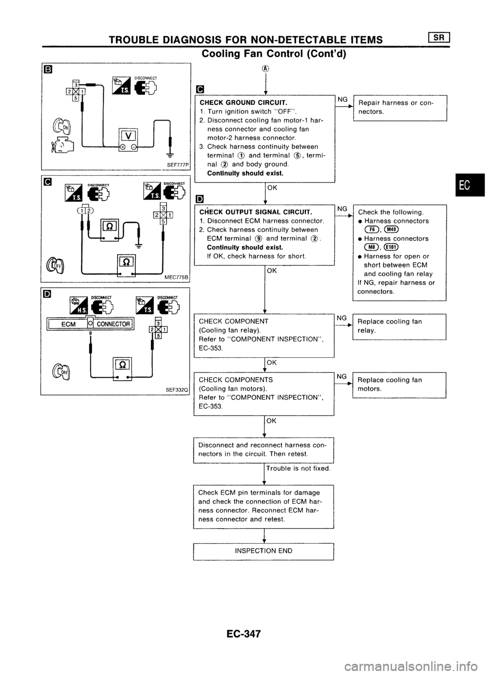
TROUBLEDIAGNOSIS FORNON-DETECTABLE ITEMS
Cooling FanControl (Cont'd)
@
SEF777P
MEC775B
~io ~i5
1=1
=EC=M=W
CONNECTOR
II~
CHECK
GROUND CIRCUIT.
1. Turn ignition switch"OFF".
2. Disconnect coolingfanmotor-1 har-
ness connector andcooling fan
motor-2 harness connector.
3. Check harness continuity between
terminal
G)
and terminal
@,
termi-
nal
@
and body ground.
Continuity shouldexist.
(!] CHECK OUTPUT SIGNALCIRCUIT.
1. Disconnect ECMharness connector.
2. Check harness continuity between
ECM terminal
@
and terminal
@.
Continuity shouldexist.
If OK, check harness forshort.
OK
CHECK COMPONENT
(Cooling fanrelay).
Refer to"COMPONENT INSPECTION",
EC-353.
OK NG
NG
NG
Repair
harness orcon-
nectors.
Check thefollowing.
• Harness connectors
(]D,@
• Harness connectors
@,@D
• Harness foropen or
short between ECM
and cooling fanrelay
If NG, repair harness or
connectors.
Replace coolingfan
relay.
•
CHECK COMPONENTS
SEF332Q
(Coolingfanmotors).
Refer to"COMPONENT INSPECTION",
EC-353.
Disconnect andreconnect harnesscon-
nectors inthe circuit. Thenretest.
Trouble isnot fixed.
Check ECMpinterminals fordamage
and check theconnection ofECM har-
ness connector. ReconnectECMhar-
ness connector andretest.
INSPECTION END
EC-347 NG
Replace coolingfan
motors.
Page 1067 of 1701
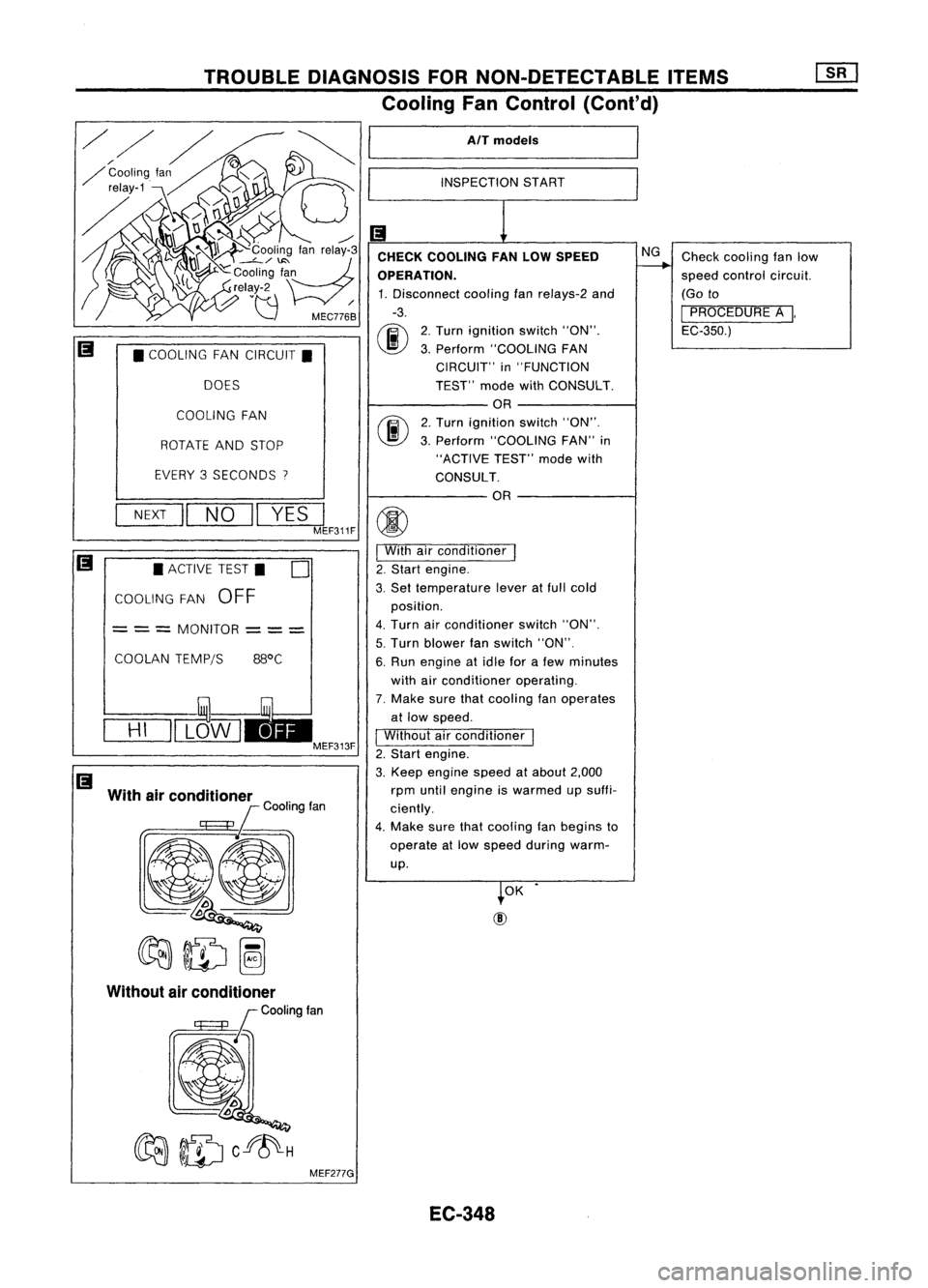
TROUBLEDIAGNOSIS FORNON-DETECTABLE ITEMS
Cooling FanControl (Cont'd)
AlT models
INSPECTION START
Checkcooling fanlow
speed control circuit.
(Go to
I
PROCEDURE A
I,
EC-350.)
NG
2. Turn ignition switch"ON".
3. Perform "COOLING FAN
CIRCUIT" in"FUNCTION
TEST" modewithCONSULT.
OR
2. Turn ignition switch"ON".
3. Perform "COOLING FAN"in
"ACTIVE TEST"modewith
CONSULT. OR
CHECK
COOLING FANLOW SPEED
OPERATION. 1. Disconnect coolingfan
re/ays-2
and
-3.
00
COOLING FAN
ROTATE ANDSTOP
EVERY 3SECONDS
I
•
COOLING FANCIRCUIT.
DOES
OK
NEXT
II
NO
II
YES
JF311F
(j)
I
With airconditioner
I
2. Start engine.
3. Set temperature leveratfull cold
position.
4. Turn airconditioner switch"ON".
5. Turn blower fanswitch "ON".
6. Run engine atidle forafew minutes
with airconditioner operating.
7. Make surethatcooling fanoperates
at low speed.
I
Without airconditioner
1
2. Start engine.
3. Keep engine speedatabout 2,000
rpm until engine iswarmed upsuffi-
ciently.
4. Make surethatcooling fanbegins to
operate atlow speed during warm-
up.
COOLAN
TEMPjS 88°C
•
ACTIVE TEST.
0
COOLING FAN
OFF
= ==
MONITOR
===
With airconditioner
lCOOtingfan
@l
~ID~
==H=I
=11L~W I
EC-348
Page 1068 of 1701
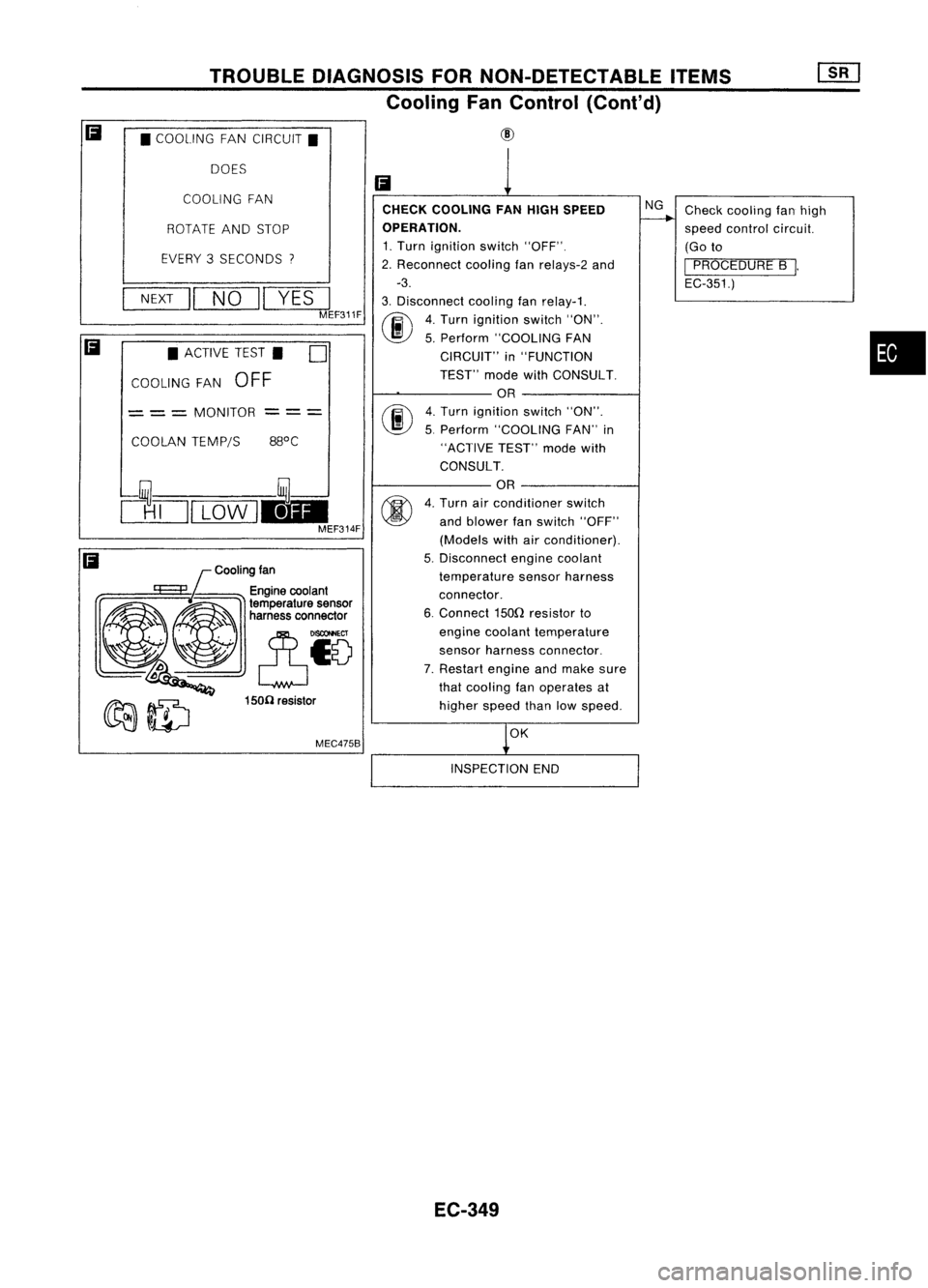
TROUBLEDIAGNOSIS FORNON-DETECTABLE ITEMS
Cooling FanControl (Cont'd)
• COOLING FANCIRCUIT.
DOES
Cooling fan
MEC475B
COOLING
FAN
•
Check
cooling fanhigh
speed control circuit.
(Go to
I
PROCEDURE B
I.
EC-351.)
NG
OK
CHECK
COOLING FANHIGH SPEED
OPERATION.
1. Turn ignition switch"OFF".
2. Reconnect coolingfanrelays-2 and
-3.
3. Disconnect coolingfanrelay-1.
(ij\
4.Turn ignition switch"ON".
~ 5.Perform "COOLING FAN
CIRCUIT" in"FUNCTION
TEST" modewithCONSULT.
OR
fiii\
4.Turn ignition switch"ON".
~ 5.Perform "COOLING FAN"in
"ACTIVE TEST"modewith
CONSULT.
OR
4. Turn airconditioner switch
and blower fanswitch "OFF"
(Models withairconditioner).
5. Disconnect enginecoolant
temperature sensorharness
connector.
6. Connect 150Qresistor to
engine coolant temperature
sensor harness connector.
7. Restart engineandmake sure
that cooling fanoperates at
higher speedthanlowspeed.
Ii
--- ---
150(1 resistor
ROTATE
ANDSTOP
EVERY 3SECONDS
"I
NEXT
II
NO
II
YES
I
MEF311F
COOLAN TEMP/S
•
ACTIVE TEST. D
COOLING FAN
OFF
= ==
MONITOR
clTJI
LOW
1.1-
MEF314F
Ii
Ii
INSPECTIONEND
EC-349
Page 1069 of 1701
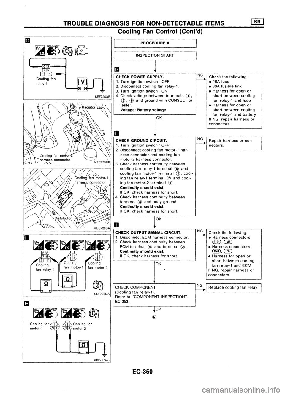
TROUBLEDIAGNOSIS FORNON-DETECTABLE ITEMS
Cooling FanControl (Cont'd)
PROCEDURE A
INSPECTION START
Checkthefollowing.
• 10A fuse
• 30A fusible link
• Harness foropen or
short between cooling
fan relay-1 andfuse
• Harness foropen or
short between cooling
fan relay-1 andbattery
If
NG, repair harness or
connectors.
Repair harness orcon-
nectors.
Replace coolingfanrelay.
Check
thefollowing.
• Harness connectors
@D,@
• Harness connectors
@,QD
• Harness foropen or
short between cooling
fan relay-1 andECM
If
NG, repair harness or
connectors.
NG
NG
NG
OK
OK
@
CHECK
GROUND CIRCUIT.
1. Turn ignition switch"OFF".
2. Disconnect coolingfanmotor-1 har-
ness connector andcooling fan
rnotor-2 harness connector.
3. Check harness continuity between
cooling fanrelay-1 terminal
@
and
cooling fanmotor-1 terminal
CD,
cool-
ing fan relay-1 terminal
(J)
and cool-
ing fan motor-2 terminal
CD.
Continuity shouldexist.
If OK, check harness forshort.
4. Check harness continuity between
terminal
@
and body ground.
Continuity shouldexist.
If
OK, check harness forshort.
CHECK COMPONENT
(Cooling fanrelay-1).
Refer to"COMPONENT INSPECTION",
EC-353.
/
0
CHECK OUTPUT SIGNALCIRCUIT.
1. Disconnect ECMharness connector.
2. Check harness continuity between
ECM terminal
@
and terminal
@.
Continuity shouldexist.
If
OK, check harness forshort.
~
I
CHECK POWER SUPPLY.
1. Turn ignition switch"OFF".
2. Disconnect coolingfanrelay-1.
3. Turn ignition switch"ON".
SEF725QB
4.Check voltage between terminals
CD,
@, @
and ground withCONSULT or
tester.
Voltage: Batteryvoltage
OK
~ SEF723QA
IJ;
3
7 5
2 1
Cooling fan
relay-1
~io~io~io
~3 .~
.-fT1
7 5 ~ ~
21.
C ,. Cooling Cooling
00
Ing
f
I1 fanmotor-1 fanmotor-2
an reay-
Cooling. fan
S S
Cooling fan
motor-1
\lliJ
~motor-2
SEF727QA EC-350
Page 1070 of 1701
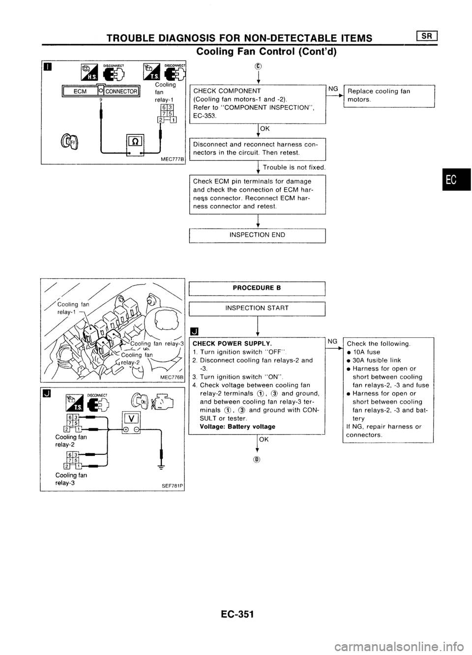
Replacecoolingfan
motors.
CHECK
COMPONENT
(Cooling fanmotors-1 and-2).
Refer to"COMPONENT INSPECTION",
EC-353.
~
INNEer
Cooling
fan
relay-1
illi
3
7
5
2 1
TROUBLE
DIAGNOSIS FORNON-DETECTABLE ITEMS
Cooling FanControl (Cont'd)
@
~
~15
ECM
~CONNECTORII
9
II
o
OK
Disconnect andreconnect harnesscon-
nectors inthe circuit. Thenretest.
Trouble isnot fixed.
Check ECMpinterminals fordamage
and check theconnection ofECM har-
ne&s connector. ReconnectECMhar-
ness connector andretest.
•
[ INSPECTION END
~i5
~-
clf:tb
Cooling fan
relay-2
~-
ffi:b
Cooling fan
relay-3
SEF781PPROCEDURE
B
INSPECTION START
CHECK POWER SUPPLY.
1. Turn ignition switch"OFF"
2. Disconnect coolingfanrelays-2 and
-3.
3. Turn ignition switch"ON".
4. Check voltage between coolingfan
relay-2 terminals
CD,
@and ground,
and between coolingfanrelay-3 ter-
minals
CD,
@and ground withCON-
SUL Tor tester.
Voltage: Batteryvoltage
OK
@
NG
Check thefollowing.
• 10A fuse
• 30A fusible link
• Harness foropen or
short between cooling
fan relays-2, -3and fuse
• Harness foropen or
short between cooling
fan relays-2, -3and bat-
tery
If
NG, repair harness or
connectors.
EC-351