NISSAN ALMERA N15 1995 Service Manual
ALMERA N15 1995
NISSAN
NISSAN
https://www.carmanualsonline.info/img/5/57349/w960_57349-0.png
NISSAN ALMERA N15 1995 Service Manual
Trending: engine coolant, wheel bolt torque, EL-136, Motor oil, jump start, turn signal, check transmission fluid
Page 1101 of 1701
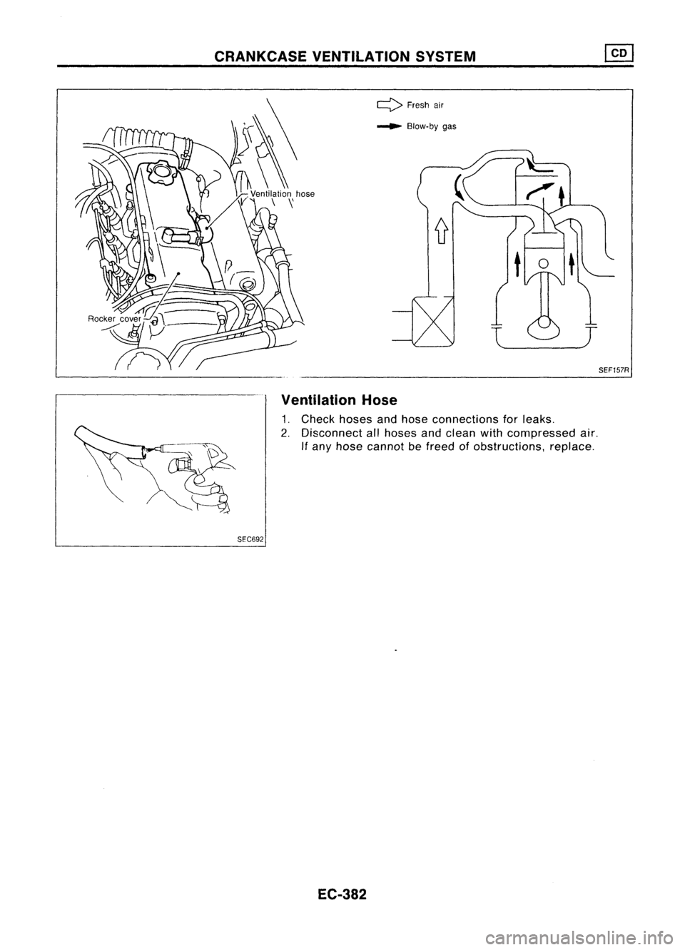
CRANKCASEVENTILATION SYSTEM
SEF157R
l
J
~
Blow-by gas
Q
Freshair
Ventilation Hose
1. Check hosesandhose connections forleaks.
2. Disconnect allhoses andclean withcompressed air.
If
any hose cannot befreed ofobstructions, replace.
SEC692
EC-382
Page 1102 of 1701
relay-2ENGINE
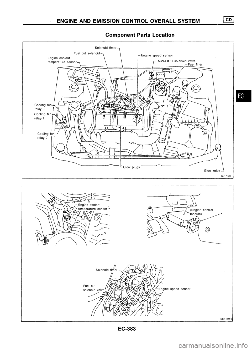
ANDEMISSION CONTROLOVERALLSYSTEM
Component PartsLocation
Engine coolant
temperature sensor
Glowplugs
•
EC-383 SEF159R
Page 1103 of 1701
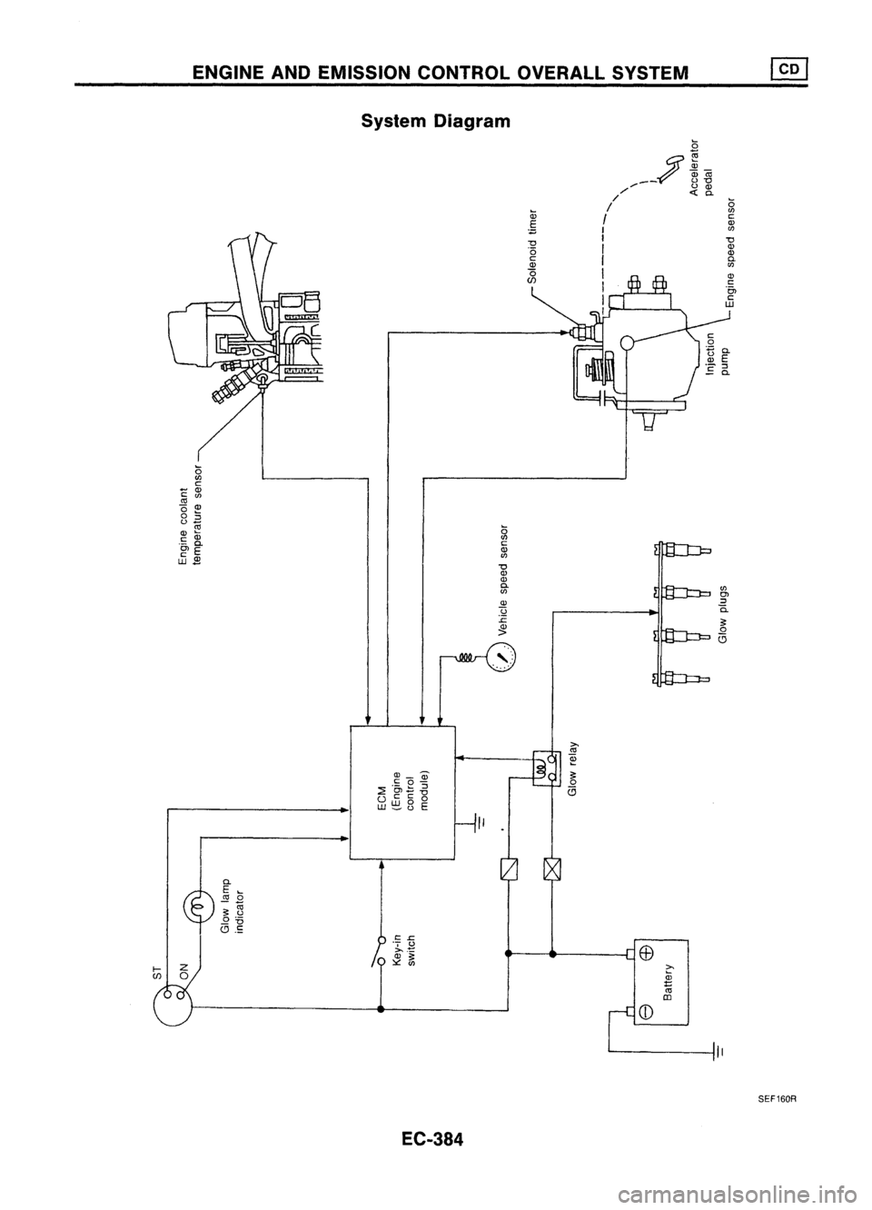
ENGINEANDEMISSION CONTROLOVERALLSYSTEM
System Diagram
~
/
~
OlCii
__ 0"'0
/' 0
OJ
//
c.
I
g
I ~
I (/)
I
"0
I
OJ
I ~
I
OJ
I
"5,
I Jj
I
c:
o
:+=:a.
~ E
'- ::l
E
c.
o
f/)
c:
- OJ
c: (/)
"0 ~
o
::l
0_
OJ ~
c:
OJ
.- c.
OlE
c:
OJ
w_
I
$
C.
E~
0
i .~
_ "0
(9.S
EC-384
g
c:
OJ
f/)
"0
OJ
OJ
C.
f/)
OJ
u
:c
~
,:
Ii .
f/)
Ol
::l
0.
SEF160R
Page 1104 of 1701
ENGINEANDEMISSION CONTROLOVERALLSYSTEM
Circuit Diagram
•
I
--:c-
~
-
U
U U I-
'"
l- I-
-
soL
H
I L
~)~
H
H
.Y.
3:
U
(T)
0-.J
3:1- 3:
roc
D
-0 ~
UJ
I- Ul
00
UlIT Ul
.rl
.M
Q
H
Ul:LIT
4 Z>
..... U
3:
N
ill
ITI-
ZI- ZO
"'-
Ul
LWZO-
Oul
0
>-ill
4
D.
IO:L
~~
H
HLIT.....
Z
~
E
I-U4
I-L 1-0
WD
4
0
HO H
I--rl
LL
LL
U
I-
Z ZUI-Ul
LL
CDZ CDU4::J
0
I
0
HO H4
CO-.-
I-
----y- L
'---11'
Ql
0 0
C
0
-rl
....,
>-
-rl
4
D
U-.J
C
"'-W
0
4IT
u
= GL
I,L
-rl
I~I
L::::::::::J
ro
vvv
0
.c
uo
....,
HH L
rl
0-
LLO
Ql
~
:L I-
IZW
....,
4 Z
>W>
Ql
Ul
-.J
.--
4
U-.J-.J
E
.....
---11' -.JW
404
0
Ql
IT lIT
OIT
HUl>
.c
TI
0 OW
0-
1-0 0 O::J
u
0
I- WI-
:L
=>H H UI-
ro
:L
8Q
WW
==0
::J
UO 0
WIT 4
....,
0
-
81t5 ;:
0-
ZW ZIT
zoo
WITIT
,-
-.JW>
ww
HWUJ ZWO W
0
0 '--W Z
W-.J-.J -.J:L
CDWZ HO-Ul IT
I-
Z 0
::J04 OH
ZO-W
CD:LZ
U
::JI
U
H -.J
IT H
LLUl> Ull-
WUlUl ZWW lUlU
4
UOO I-
WI-Ul-.JUlI-
3: HWUl
U
,-11'
I'
(
~
4
WI-<
0
IWZ
W
=>IT3:
-.J WO-W
J
~
~
V
OO-ul
CD >Ulul
Z
H
I
IT
LO
(D
OJr--
~
0'1
(D
OJ
....
r--
....
LO
....
s:
....
(\j
0'1 0'1
(\j
SS
~ r--
0'1
ECM(ENGINECONTROLMODULE)
H
~ LO
(\j
(D
OJ
0
OJ
0
010
(D
01
(\j
0'10'1
....
(\j
0'1
I
j
CD
....
Z I
H
>-
-.J
~0
OZ-.J
O
ULLIT
~-
=
=
~
CD
(\j
t-
ZI
Ul
H
>-
2:
z
-.J
0
ZI
OZ-.J
:1
1
HU
~
04W
u
II- ULLITCD
....
U
>-1-<
~
Z
I
W3: H
IT
LL
'Y.UJ
~
-.J0
LL
>-
-f-o
0
3:4 OZI-
O-.J
=
~I'
040
-.JW
~
-
f-o
0-
ULL:L
CD IT
I'
=
~
6
CD
~
::J
~
I'
-.J
m
6
0-
CD
(Y]
=
Z
I
3: H
>-
I'
0
-.J
-
I'
6
-.J
OZ-.J@ CD
(\j
19
8L;':~
I
~~ ~~~
~
H
IT:
I'
~
-.J
0
L..:..'J
-I'
000,
OZI-
(g)
>-
8L;':~
4
IT:
=
~
W
I~~I'
"-'
I'
l-
I-
4
ill
I
U
I-
H
3:
UJ
Z
o
H
I-
H
Z
CD
I-<
W
-.J
ill
H
Ul
::J
LL
HEeD8?
EC-385
Page 1105 of 1701
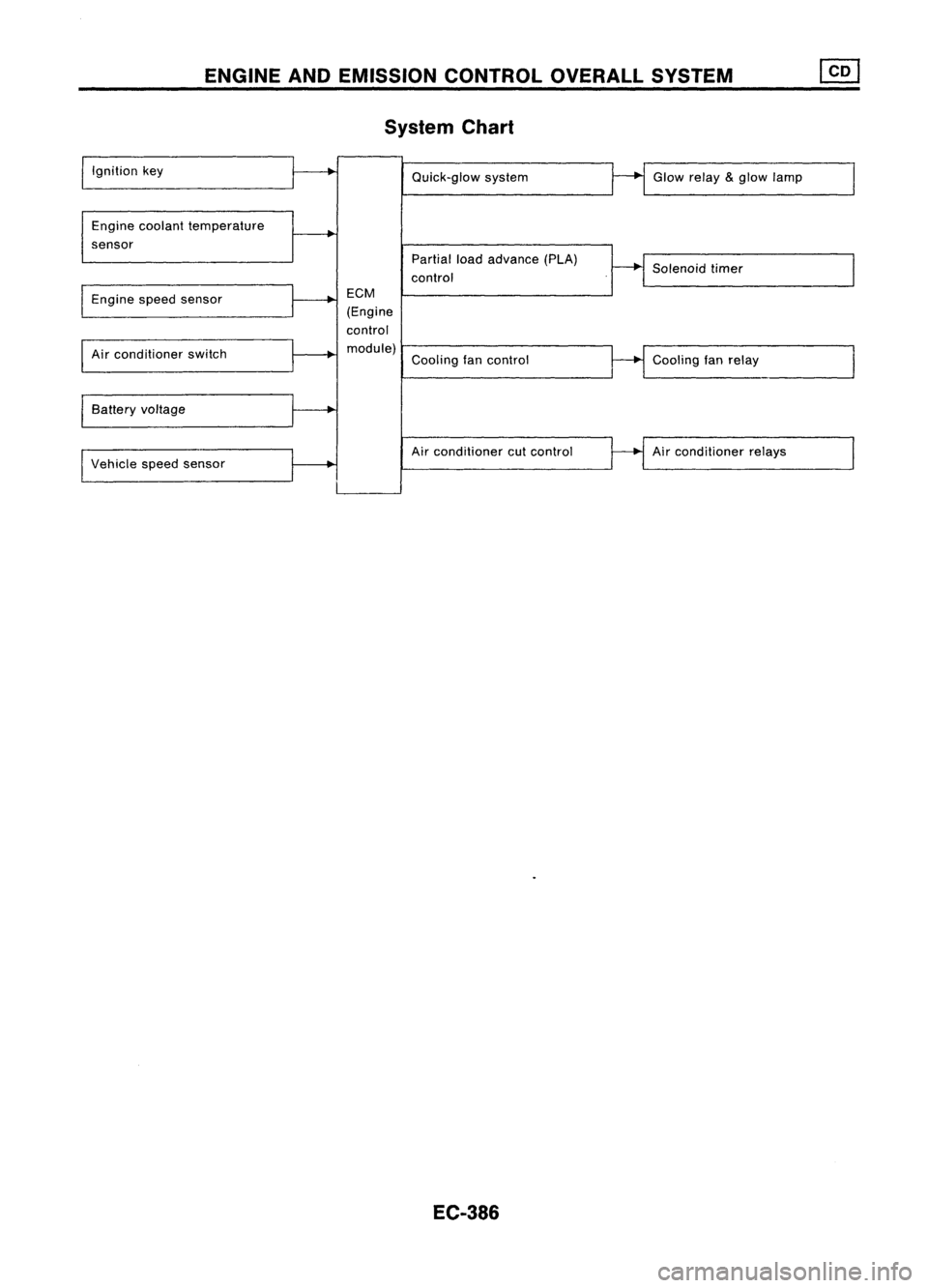
ENGINEANDEMISSION CONTROL OVERALLSYSTEM
System Chart
Ignition key
Engine coolant temperature
sensor Quick-glow
system
Partial loadadvance (PLA)
control Glow
relay
&
glow lamp
Solenoid timer
Engine speedsensor
Air conditioner switch
Battery voltage
Vehicle speedsensor
ECM
(Engine
control module) Coolingfancontrol
Air conditioner cutcontrol
EC-386
Cooling
fanrelay
Air conditioner relays
Page 1106 of 1701
TROUBLEDIAGNOSES
ECM Terminals andReference Values
PREPARATION
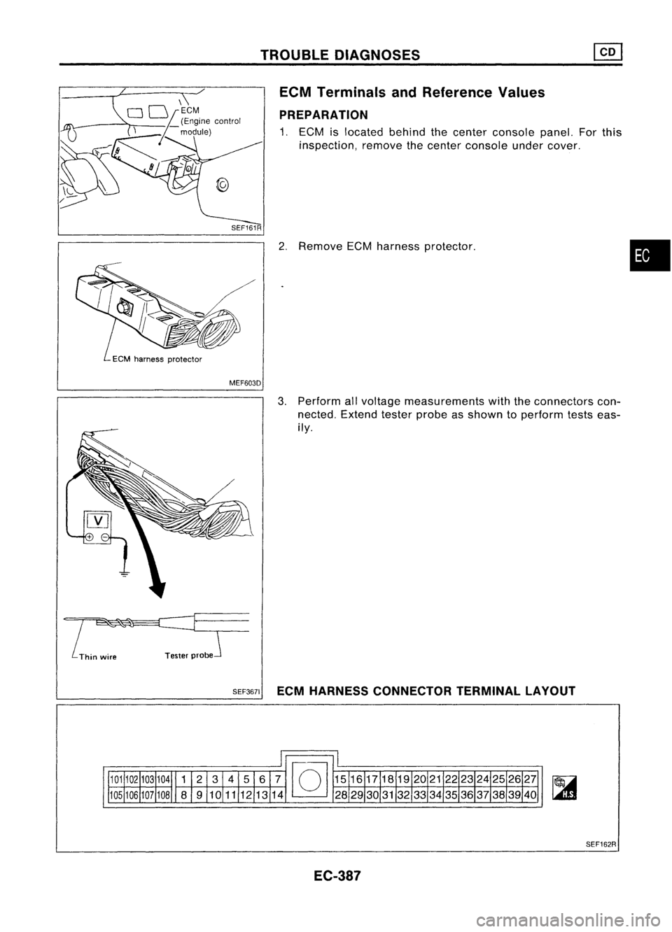
1. ECM islocated behindthecenter console panel.Forthis
inspection, removethecenter console undercover.
2. Remove ECMharness protector.
•
MEF603D
!~
Thin wire TesterprobeJ 3.
Perform allvoltage measurements withtheconnectors con-
nected. Extendtesterprobeasshown toperform testseas-
ily.
SEF3671 ECMHARNESS CONNECTOR TERMINALLAYOUT
SEF162R
EC-387
Page 1107 of 1701
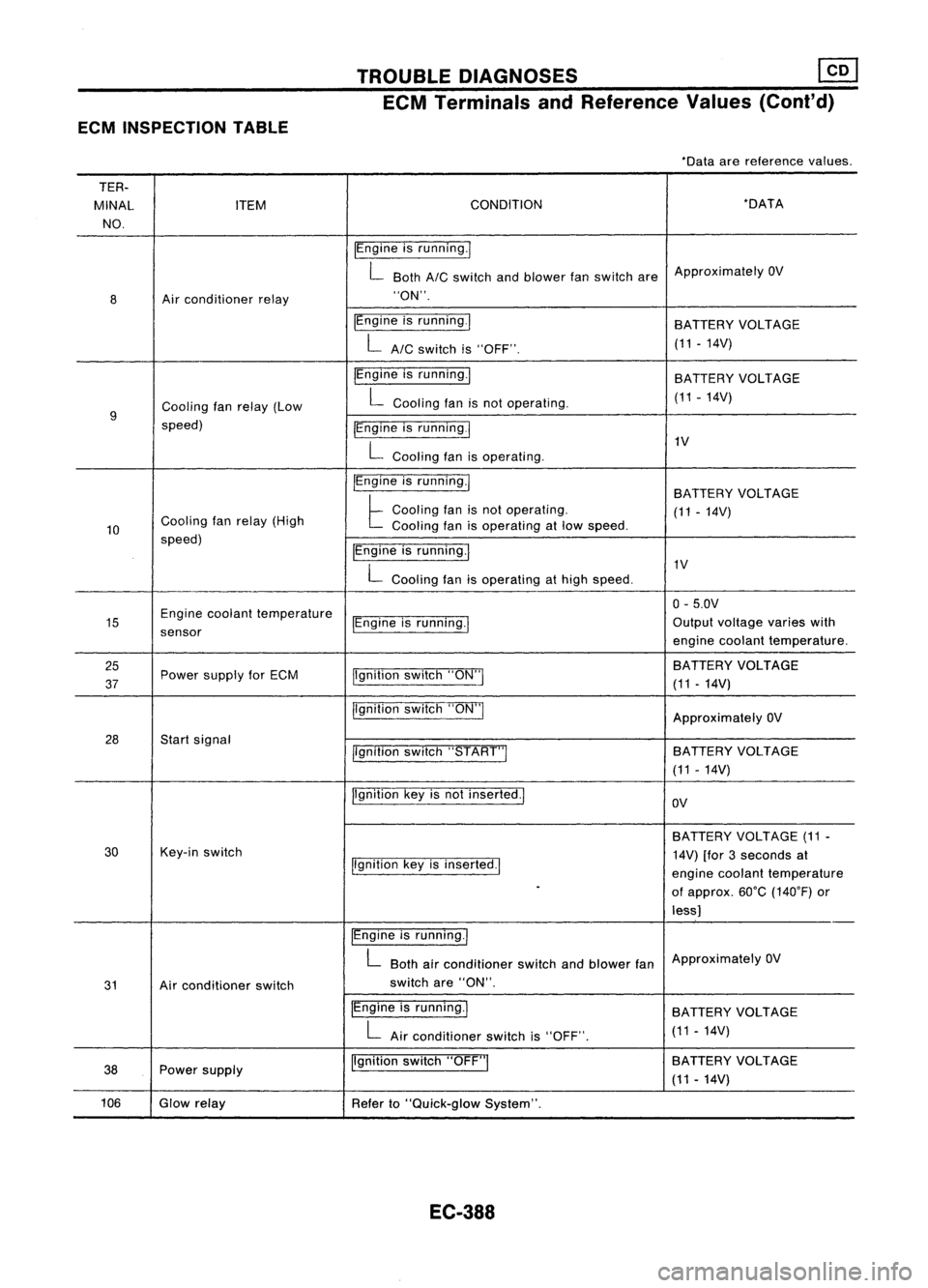
ECMINSPECTION TABLE TROUBLE
DIAGNOSES ~
ECM Terminals andReference Values(Coni'd)
-Data arereference values.
TER-
MINAL ITEM CONDITION -DATA
NO.
IEngineisrunning.1
L Both
AIC
switch andblower fanswitch areApproximately
OV
8 Air
conditioner relay "ON".
IEngine isrunning.1
BATTERYVOLTAGE
LAIC switchis"OFF". (11
-14V)
IEngine isrunning.1
BATTERY VOLTAGE
Cooling fanrelay (Low L
Cooling fanisnot operating. (11-14V)
9
speed) IEngineisrunning
I
L
Cooling fanisoperating. 1V
IEngine isrunning.1
BATTERYVOLTAGE
Cooling fanrelay (High
t
Cooling fanisnot operating.
(11-14V)
10 Cooling
fanisoperating atlow speed.
speed) IEngineisrunning.1
L
Cooling fanisoperating athigh speed. 1V
0- 5.0V
15 Engine
coolant temperature
IEngineisrunning.1 Output
voltage varieswith
sensor enginecoolant temperature.
25 jlgnitionswitch"ON"I BATTERY
VOLTAGE
37 Power
supply forECM
(11-14V)
jlgnition switch"ON"I
ApproximatelyOV
28 Startsignal
llgnitionswitch"START"I SA
TTERY VOLTAGE
(11 -14V)
Ilgnition keyisnot inserted.1
OV
BATTERY VOLTAGE (11-
30 Key-in
switch
14V)[for3seconds at
Ilgnition keyisinserted.1
enginecoolant temperature
-
ofapprox. 60°C(140°F) or
less)
IEngine isrunning.1
L
Both airconditioner switchandblower fanApproximately
OV
31 Airconditioner switch switch
are"ON".
IEngine isrunning.1
BATTERYVOLTAGE
L
Airconditioner switchis"OFF". (11
-14V)
38 Power
supply Ilgnition
switch"OFF"I BATTERY
VOLTAGE
(11 -14V)
106 Glowrelay
Referto"Quick-glow System".
EC-388
Page 1108 of 1701
TROUBLEDIAGNOSES ~
ECM Terminals andReference Values(Cont'd)
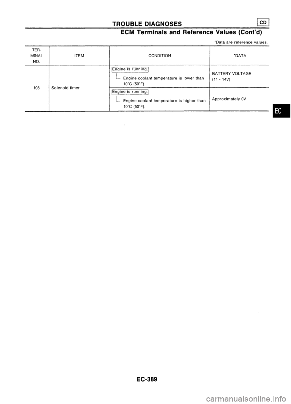
*Data arereference values.
TER-
MINAL ITEM CONDITION
*DATA
NO.
IEngineisrunning.1
BATTERYVOLTAGE
L
Engine coolant temperature islower than
(11-14V)
we
(50'F).
108 Solenoid timer
/Engineisrunning.1
L
Engine coolant temperature ishigher than Approximately
OV
we
(50'F).
EC-389
•
Page 1109 of 1701
TROUBLEDIAGNOSES
Quick-glow System
SYSTEM DESCRIPTION
Ignition key
Engine coolant temperature sensorKey-in
switch andkeyposition
Engine coolant temperature
ECM
(Engine
control
module) Glow
relay
Glow lamp Glow
plugs
Ignition START[~
~
switch
~~[ I
11
I
1iI
Key
~
switch OUT
-II-
T,
I
!
I
I-l
Key ONe
n
Hn
JTl-
.1"l....!:.1L-
~
timer
OFF
Ir1
To
I
UL
HTo
HT'o
Lamp ON
[
..Lfl
o~~
I
I-.J
TL
I
~
I
I-l
TL
I
I
I
I
I
HTL
I-l
T'L
Relay OFF
[j
I_
L-
r--L
.f"l.-.JL
~
T.
"'
II
I
II
~
1r;,1
I II I
I,
Glow plug
temperature
Normaloperation
Operationafter
key timer isOFF Leaving
keyin
ON position Repeating
keyIN
and OUT Repeating
keyON
and OFF
TL
=
T,-T,
when T,-0.5 >T,
TL
= T,
when T,-0.5 ~T,
;a;
To
TL
=.
T,
when To
<
T, T'o
~80% ofTo
when T.
5':
3sec.
T',
=.
T,
T',
=.
T,
SEC550B
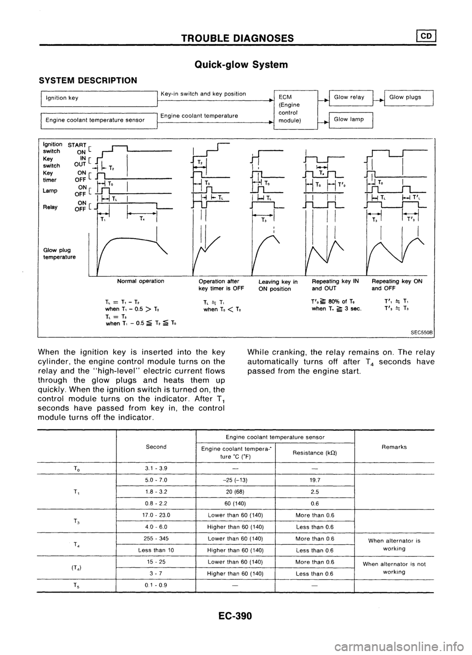
When theignition keyisinserted intothekey
cylinder, theengine control module turnsonthe
relay andthe"high-level" electriccurrentflows
through theglow plugs andheats themup
quickly. Whentheignition switchisturned on,the
control module turnsonthe indicator. AfterT
1
seconds havepassed fromkeyin,the control
module turnsoffthe indicator. While
cranking, therelay remains on.The relay
automatically turnsoffafter T
4
seconds have
passed fromtheengine start.
Engine coolant temperature sensor
Second Enginecoolant tempera-' Remarks
ture 'C('F) Resistance
(kQ)
To
3.1
-3.9
- -
5.0 -7.0 -25(-13)
19.7
T,
1.8
-3.2
20(68)
2.5
0.8 -2.2 60(140)
0.6
17.0 -23.0
Lowerthan
60(140)
Morethan
0.6
T
3
40-6.0
Higherthan
60(140)
Lessthan
0.6
255 -345
Lowerthan
60(140)
Morethan
0.6
Whenalternator is
T
4
working
Less than
10
Higherthan
60(140)
Lessthan
0.6
15 -25
Lowerthan
60(140)
Morethan
0.6
Whenalternator isnot
(T
4)
working
3 -7
Higherthan
60(140)
Lessthan
0.6
T
5
0.1-0.9
- -
EC-390
Page 1110 of 1701
TROUBLEDIAGNOSES
Quick-glow System(Cont'd)
DESCRIPTION
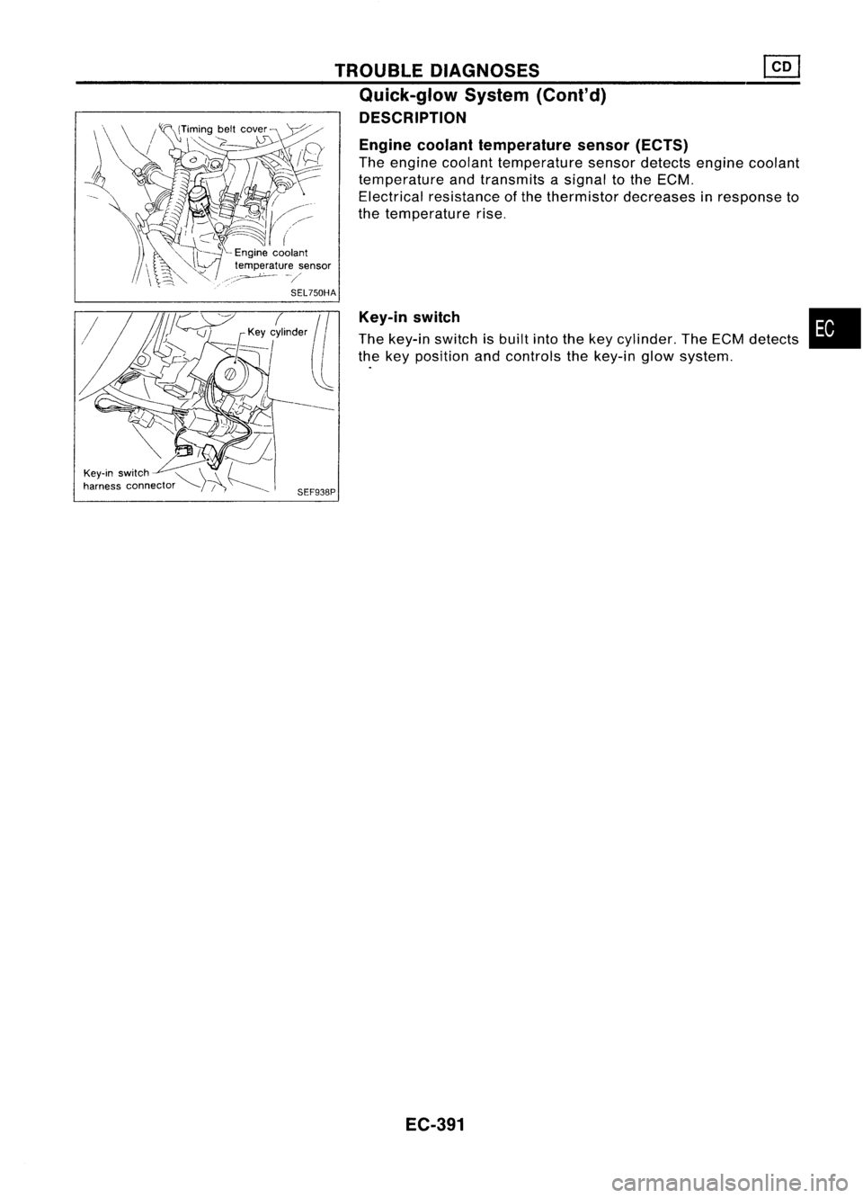
Engine coolant temperature sensor(ECTS)
The engine coolant temperature sensordetects enginecoolant
temperature andtransmits asignal tothe ECM.
Electrical resistance ofthe thermistor decreases inresponse to
the temperature rise.
Key-in switch
The key-in switch isbuilt intothekey cylinder. TheECM detects
the key position andcontrols thekey-in glowsystem.
SEF938P
EC-391
•
Trending: airbag connector, belt, jump start, rear view mirror, Tachome, wheel, reset
