NISSAN ALMERA N15 1995 Service Manual
Manufacturer: NISSAN, Model Year: 1995, Model line: ALMERA N15, Model: NISSAN ALMERA N15 1995Pages: 1701, PDF Size: 82.27 MB
Page 1191 of 1701
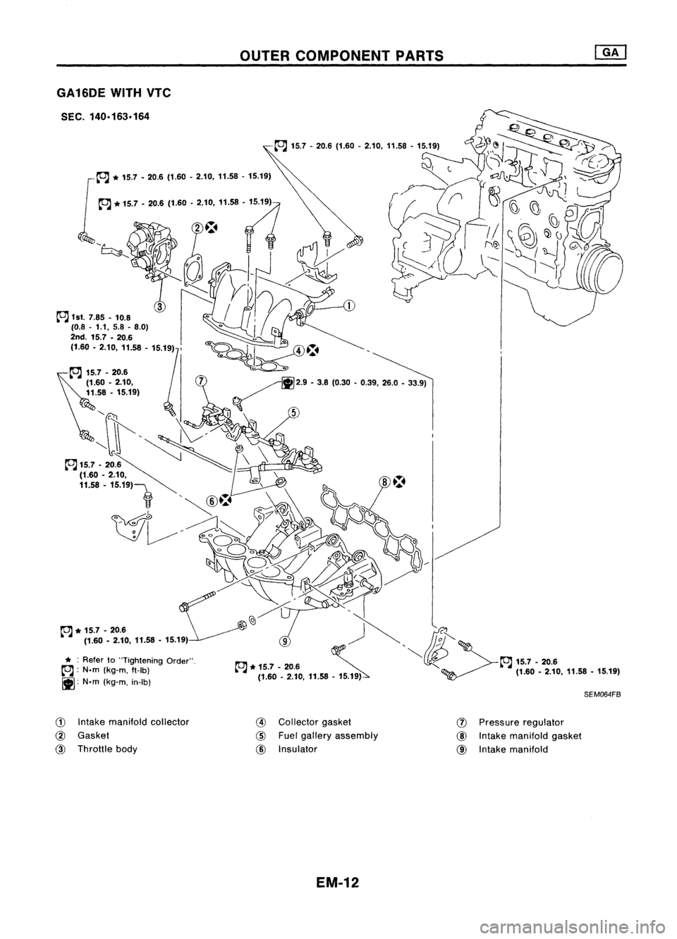
GA16DEWITHVTC
SEC. 140.163.164
~ 1st.
7.85 •10.8
(0.8. 1.1,5.8.8.0)
G)
Intake manifold collector
@
Gasket
@
Throttle body
OUTER
COMPONENT PARTS
@
Collector gasket
@
Fuelgallery assembly
@
Insulator
EM-12
(J)
Pressure regulator
@
Intake manifold gasket
@
Intake manifold
SEM064FB
Page 1192 of 1701
OUTERCOMPONENT PARTS
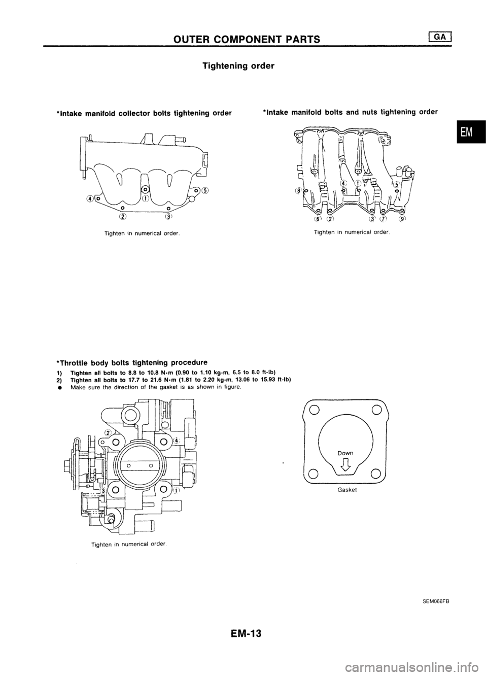
Tightening order
*
Intake manifold collector boltstightening order
Tighten innumerical order.
*Intake
manifold boltsandnuts tightening order
Tighten innumerical order.
•
*Throttle bodybolts tightening procedure
1) Tighten allbolts to8.8 to10.8 N.m (0.90 to1.10 kg-m, 6.5to8.0 ft-Ib)
2) Tighten allbolts to17.7 to21.6 N.m (1.81 to2.20 kg-m, 13.06to15.93 ft-Ib)
• Make surethedirection ofthe gasket isas shown infigure.
Tighten innumerical order
EM-13
o
,,-0
Gasket
o
SEM066FB
Page 1193 of 1701
OUTERCOMPONENT PARTS
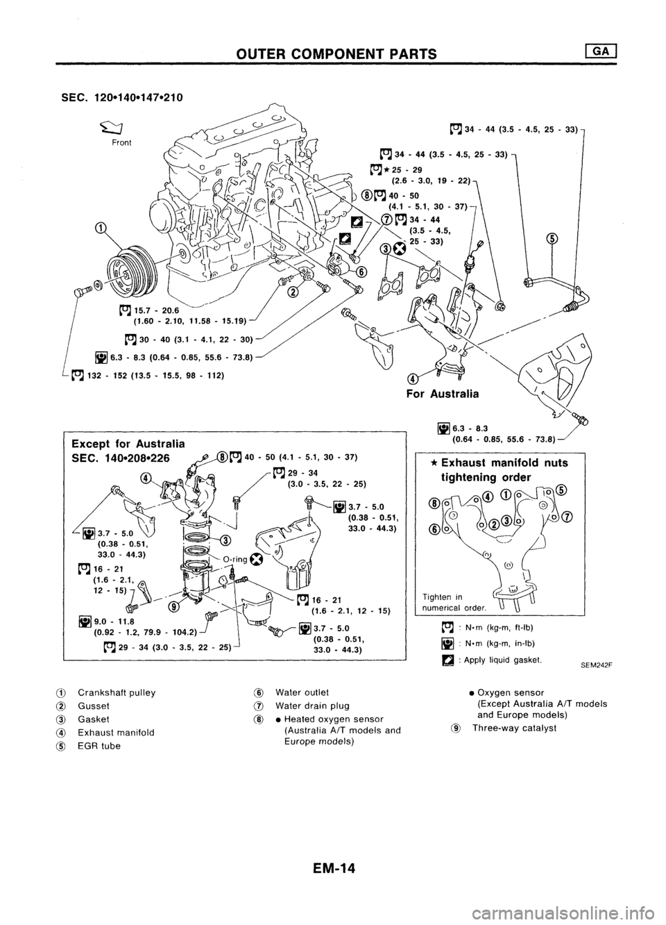
SEC. 120-140-147-210
Front
Except forAustralia
SEC. 140-208-226
P::~
40•50 (4.1 •5.1, 30•37)
~ ~~29-34
L
'r•,
t::~
(3.0-3.5, 22-25)
I'! - ~
r.e.t
r r
tf------- ~
3.7 -5.0
c -____
J
~l
(0.38•0.51,
~37'~
f'~~~
330-4431
(0.38 -0.51, ~
~Q;f;~
330 -443)
Ji
O'
L"'}.
J)
~ -rlng~
r
[O;J
16-21 _
y-' "
(1.6 -2.1, ~ ---
~~~I
12 •15) '\ ,-"
-- - .•to.]
16-21
!il',0 _
,,+ ·<1J1'>:t;)
(1.• -
2.1,
12-15)
(0.92 -1.2, 79.9_104.2).../ ~1iI3.7-5.0
rrTl
(0.38•0.51,
~-~ 29-34 (3.0 •3.5, 22•25) 33.0•44.3)
4
For Australia
Tighten in
numerical order.
~ :N.m (kg-m, ft-Ib)
1iI :N'm (kg-m, in-Ib)
a :
Apply
liquidgasket.
5
SEM242F
G)
Crankshaft pulley
@
Gusset
@
Gasket
@
Exhaust manifold
@
EGR tube
@
Water outlet
IJ)
Water drainplug
@ •
Heated oxygen sensor
(Australia
AIT
models and
Europe models)
EM-14
•
Oxygen sensor
(Except Australia
AIT
models
and Europe models)
@
Three-way catalyst
Page 1194 of 1701
COMPRESSIONPRESSURE
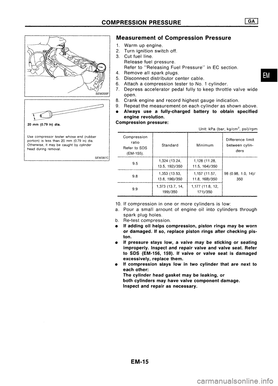
20
mm
(O.79 In)dls.
Use compressor testerwhose end(rubber
portion) isless than 20mm (0.79 in)dia.
Otherwise, itmay becaught bycylinder
head during removal.
SEM387CMeasurement
ofCompression Pressure
1. Warm upengine.
2. Turn ignition switchoff.
3. Cut fuel line.
Release fuelpressure.
Refer to"Releasing FuelPressure" inEC section. •
4. Remove allspark plugs.
5. Disconnect distributorcentercable.
6. Attach acompression testertoNO.1 cylinder.
7. Depress accelerator pedalfullytokeep throttle valvewide
open.
8. Crank engine andrecord highest gaugeindication.
9. Repeat themeasurement oneach cylinder asshown above.
• Always useafully-charged batterytoobtain specified
engine revolution.
Compression pressure:
Unit:kPa(bar, kg/cm
2,
psi)/rpm
Compression Differencelimit
ratio
Standard
Refer toSOS Minimum
betweencylin-
(EM-155). ders
9.5 1,324
(13.24, 1,128(11.28,
13.5, 192)/350 11.5,164)/350
9.8 1,353
(1353, 1,157(11.57, 98(0.98, 1.0,14)/
13.8, 196)/350 11.8,168)/350
350
9.9 1,373
(13.7, 14, 1,177(11.8,12,
199)/350 171)/350
10.
If
compression inone ormore cylinders islow:
a. Pour asmall amount ofengine oilinto cylinders through
spark plugholes.
b. Re-test compression,
• Ifadding oilhelps compression, pistonringsmaybeworn
or damaged. Ifso, replace pistonringsafterchecking pis-
ton.
• Ifpressure stayslow,avalve maybesticking orseating
improperly. Inspectandrepair valveandvalve seat.Refer
to SOS (EM-156, 159).Ifvalve orvalve seatisdamaged
excessively, replacethem.
• Ifcompression stayslowintwo cylinder thatarenext to
each other:
The cylinder headgasket maybeleaking, or
both cylinders mayhave valve component damage.
Inspect andrepair asnecessary.
EM-15
Page 1195 of 1701
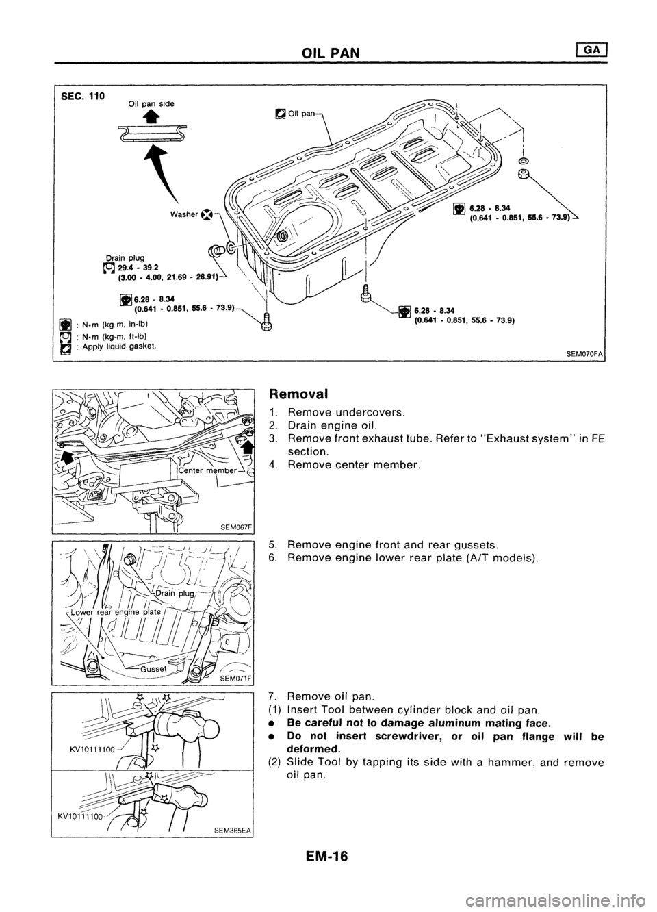
SEC.110
OIL
PAN
SEM070FA
Removal
1. Remove undercovers.
2. Drain engine oil.
3. Remove frontexhaust tube.Refer to"Exhaust system"inFE
section.
4. Remove centermember.
5. Remove enginefrontandrear gussets.
6. Remove enginelowerrearplate (AfTmodels).
7. Remove oilpan.
(1) Insert Toolbetween cylinderblockandoilpan.
• Becareful nottodamage aluminum matingface.
• Do not insert screwdriver, oroil pan flange willbe
deformed.
(2) Slide Toolbytapping itsside withahammer, andremove
oil pan.
EM-16
Page 1196 of 1701
OilPAN
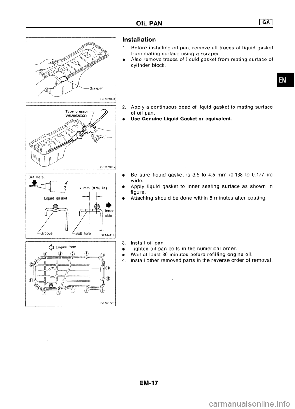
SEM295C Installation
1. Before installing oilpan,
remove
alltraces ofliquid gasket
from mating surface usingascraper.
• Also
remove
tracesofliquid gasket frommating surface of
cylinder block.
•
Cut here.
liquid gasket
7
mm
(0.28
in)
-1 ~
•
Inner
side
2.
Apply acontinuous beadofliquid gasket tomating surface
of oil pan.
• Use Genuine LiquidGasket orequivalent.
• Besure liquid gasket is3.5 to4.5 mm (0.138 to0.177 in)
wide.
• Apply liquidgasket toinner sealing surface asshown in
figure.
• Attaching shouldbedone within 5minutes aftercoating.
Q
Engine front
@
@
CV
@
@
~ ==O=O=O~o
@o~L-J~\
I
%
~ ~C:;;;}Oc=J/
I
_/o@
~ =:J
Of
i~
([Do
:=JODI
I
o@
~\I
JL.-=o=o
0
~ =
0~---
<:::::==
(j)
CIDCDW
@
SEM072F
3.
Install oilpan.
• Tighten oilpan bolts inthe numerical order.
• Wait atleast 30minutes beforerefilling engineoil.
4. Install other
removed
partsinthe reverse orderof
removal.
EM-17
Page 1197 of 1701
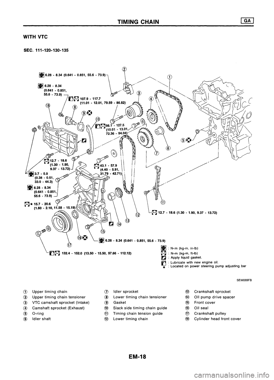
TIMINGCHAIN
WITH VTC
SEC. 111.120.130.135
~~
\£It''J
132.'.152.•(13 .... 15.... 97.&6 .112.12)
SEM069FB
CD
Upper timing chain
@
Upper timing chaintensioner
@
VTCcamshaft sprocket(Intake)
@
Camshaft sprocket(Exhaust)
@
O-ring
@
Idler shaft
(J)
Idlersprocket
@
Lower timing chaintensioner
@
Gasket
@)
Slack sidetiming chainguide
@
Timing chaintension guide
@
Lower timing chain
EM-18 @
Crankshaft sprocket
@
Oilpump drivespacer
@
Front cover
@
Oilseal
@
Crankshaft pulley
@
Cylinder headfrontcover
Page 1198 of 1701
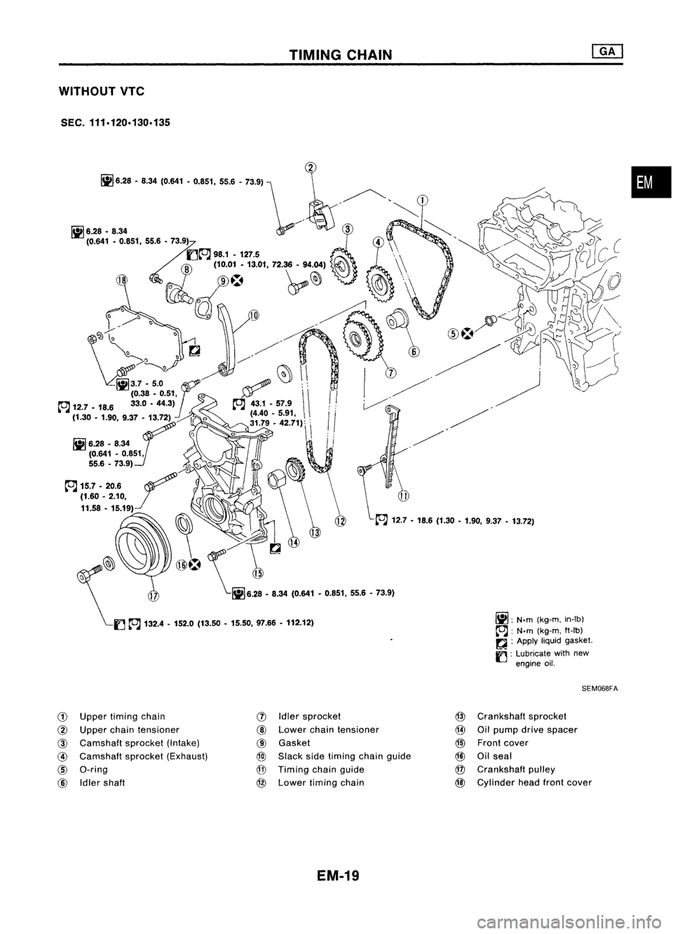
WITHOUT VTC
SEC. 111.120.130.135
G)
Upper timing chain
@
Upper chaintensioner
@
Camshaft sprocket(Intake)
@
Camshaft sprocket(Exhaust)
@)
a-ring
@
Idler shaft
TIMING
CHAIN
(j)
Idler sprocket
@
Lower chaintensioner
@
Gasket
@
Slack sidetiming chaingUide
@
Timing chainguide
@
Lower timing chain
EM-19
~:
N.m
(kg-m,
in-lb)
~ :N'm
(kg-m, ft-Ib)
~ :Apply
liquidgasket.
fJ :
Lubricate withnew
engine oil.
SEM068FA
@
Crankshaft sprocket
@
Oilpump drivespacer
@)
Front cover
@
Oilseal
@
Crankshaft pulley
@
Cylinder headfrontcover
•
Page 1199 of 1701
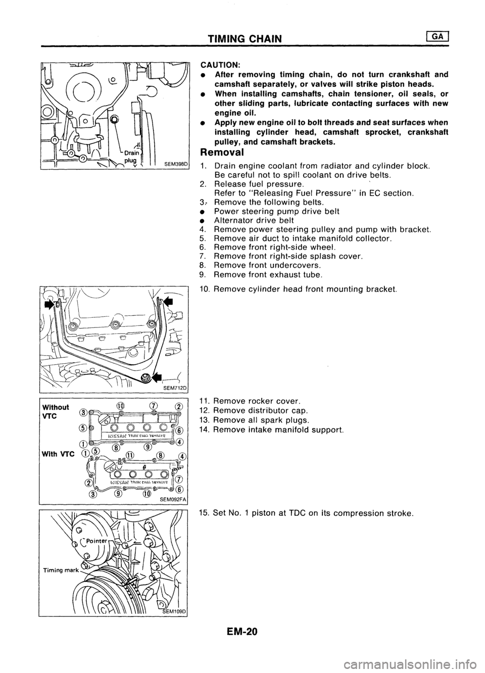
TIMINGCHAIN
Without
VTC
CAUTION:
• After removing timingchain,donot turn crankshaft and
camshaft separately, orvalves willstrike piston heads.
• When installing camshafts, chaintensioner, oilseals, or
other sliding parts,lubricate contacting surfaceswithnew
engine oil.
• Apply newengine oiltobolt threads andseat surfaces when
installing cylinderhead,camshaft sprocket,crankshaft
pulley, andcamshaft brackets.
Removal
1. Drain engine coolant fromradiator andcylinder block.
Be careful nottospill coolant ondrive belts.
2. Release fuelpressure. '
Refer to"Releasing FuelPressure" inEG section.
3.. Remove thefollowing belts.
• Power steering pumpdrivebelt
• Alternator drivebelt
4. Remove powersteering pulleyandpump withbracket.
5. Remove airduct tointake manifold collector.
6. Remove frontright-side wheel.
7. Remove frontright-side splashcover.
8. Remove frontundercovers.
9. Remove frontexhaust tube.
10. Remove cylinderheadfrontmounting bracket.
11. Remove rockercover.
12. Remove distributor cap.
13. Remove allspark plugs.
14. Remove intakemanifold support.
15. Set NO.1 piston at
TOG
onitscompression stroke.
EM-20
Page 1200 of 1701
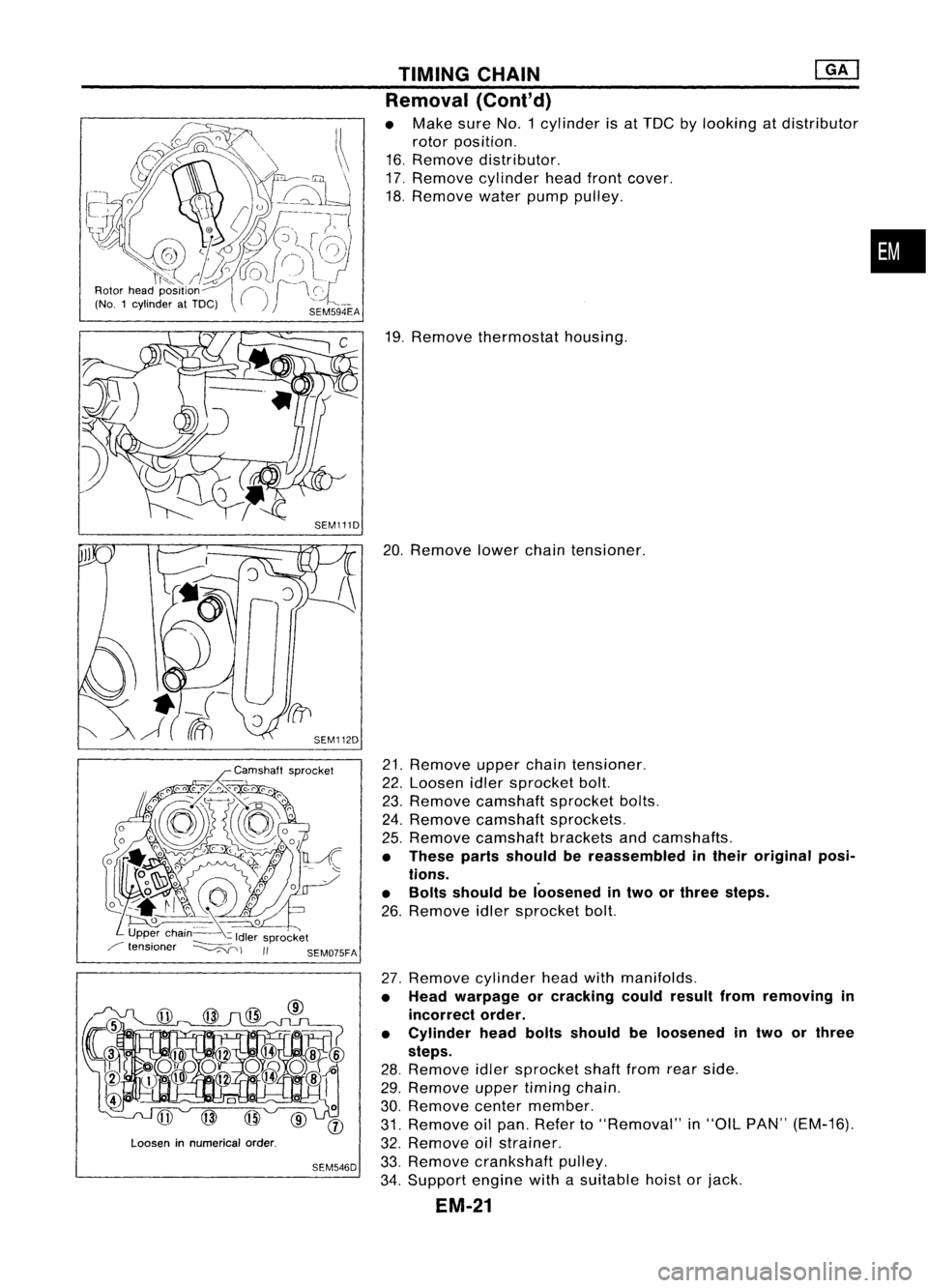
Looseninnumerical order.
SEM546D TIMING
CHAIN @KJ
Removal (Cont'd)
• Make sureNo.1 cylinder isat TDC bylooking atdistributor
rotor position.
16. Remove distributor.
17. Remove cylinder headfrontcover.
18. Remove waterpumppulley.
19. Remove thermostat housing.
20. Remove lowerchaintensioner.
21. Remove upperchaintensioner.
22. Loosen idlersprocket bolt.
23. Remove camshaft sprocketbolts.
24. Remove camshaft sprockets.
25. Remove camshaft bracketsandcamshafts.
• These partsshould bereassembled intheir original posi-
tions.
• Bolts should beloosened intwo orthree steps.
26. Remove idlersprocket bolt.
27. Remove cylinderheadwithmanifolds.
• Head warpage orcracking couldresult fromremoving in
incorrect order.
• Cylinder headboltsshould beloosened intwo orthree
steps.
28. Remove idlersprocket shaftfromrearside.
29. Remove uppertiming chain.
30. Remove centermember.
31. Remove oilpan. Refer to"Removal" in"OIL PAN" (EM-16).
32. Remove oilstrainer.
33. Remove crankshaft pulley.
34. Support enginewithasuitable hoistorjack.
EM-21
•