NISSAN ALMERA N15 1995 Service Manual
ALMERA N15 1995
NISSAN
NISSAN
https://www.carmanualsonline.info/img/5/57349/w960_57349-0.png
NISSAN ALMERA N15 1995 Service Manual
Trending: engine coolant, B111, instrument panel, headlights, E211, oil capacity, brake rotor
Page 1161 of 1701
ENGINECOOLING SYSTEM ~
Water Pump(Cont'd)
INSTAllATION
1, Before installing, removealltraces ofliquid gasket from
mating surface ofwater pumpusingascraper.
• Also remove tracesofliquid gasket frommating surface of
cylinder block.
SLC433A
•
~ Liquid gasket
SLC434A
2.
Apply acontinuous beadofliquid gasket tomating surface
of water pump,
• Use Genuine LiquidGasket orequivalent.
Thermostat
\~to:J
16-21 (1.6 -2.1, 12-15)
oj;
[OJ .
N'm (kg-m, fHb)
~ :N'm (kg-m, in-Ib)
SEC.
210 ~--
!i1I6.3 •8.3 (0.64 -0.85, 55.6-73.8) -,
~'i;JJ;'
r;.~ ''(
m
63 •83 A'I'
f
1
I
Thermostat
7- /;;
III' .
IrreIe pug ,"
(0.64 .0.• 5,
55.•.
73.6)
I
(if"
,q";PP'dl'\~."_,, __
h~,O,
USIn~,-",
0,:'/
\ Thoem"t".,
~1r
J
[OJ
;:6- _2~.1,
12 -15)
, [OJ
16-21 (1.6 -2.1, 12-15)
O~ ,~,
,~)~~\-~~~ ~~~~~t~~~~~:t -\
I[~J ~'- -
--O~
/-..... 2.0-3.0mm I~
)!
~( a
(0.079 -0.118 in) (2.0-3.0 mm
2 -
/0
0
(0.079.0.118in)
~1
SLC050B
LC-23
Page 1162 of 1701

Upper REMOVALANDINSTAllATION
;::g=
Jigglevalve
1.Drain engine coolant.
2. Remove lowerradiator hose.
3. Remove waterinlet,thentake outthermostat.
4.")
ENGINECOOLING SYSTEM ~
Thermostat
(Cont'd)
Upper REMOVALANDINSTAllATION
;::g=
Jigglevalve
1.Drain engine coolant.
2. Remove lowerradiator hose.
3. Remove waterinlet,thentake outthermostat.
4. Install thermostat withjiggle valveorair bleeder facing
upward.
• After installation, runengine forafew minutes, andcheck
for leaks.
• Becareful nottospill coolant overengine compartment.
Use arag toabsorb coolant.
SLC767
INSPECTION
1. Check forvalve seating condition atordinary temperatures.
It
should seattightly.
2. Check valveopening temperature andvalve lift.
Valve opening temperature
°c
(OF) 76.5(170)
Valve lift mmrC(inrF) Morethan
8/90(0.31/194)
3. Then check ifvalve closes at5°C (9°F) below valveopening
temperature.
Water Outlet
INSPECTION
Visually inspectforwater leaks.
If
there isleakage, applyliq-
uid gasket.
SLC460A INSTAllATION
1. Before installing, removealltraces ofliquid gasket from
mating surface ofwater outlet usingascraper.
• Also remove tracesofliquid gasket frommating surface of
cylinder head.
2. Apply acontinuous beadofliquid gasket tomating surface
of water outlet. .
• Use Genuine LiquidGasket orequivalent.
~ Liquid gasket
SEM086D
LC-24
Page 1163 of 1701
SEC.214
10
ENGINE
COOLING SYSTEM
Radiator
SLC039BA
•
CD
Reservoir tank
@
Reservoir tankbracket
@
Radiator cap
@
Mounting bracket
CID
Upper hose
@
Washer
(J)
Drain plug
CID
Mounting rubber
@
Oilcooler hose
(AfT
models)
@)
Radiator
@
Lower hose
@
Cooling fan
@
Cooling fanmotor
Cooling fancontrol system
• Cooling fansarecontrolled bythe ECM. Fordetails, referto
EC section ("Cooling FanControl", "TROUBLE
DIAGNOSES").
Refilling enginecoolant
• For details onrefilling enginecoolant, refertoMA section
("REFILLING ENGINECOOLANT", "ChangingEngine
Coolant").
LC-25
Page 1164 of 1701
ENGINELUBRICATION SYSTEM
Lubrication Circuit
Note: .. :Oil gallery incylinder block
~ :Oil passage
.... -:By-pass passage
II
Hydraulic valve
lifter
Oil
cooler
Relief valve
0
Oil
filter
Oil
pump
SLC609AA
LC-26
Page 1165 of 1701

ENGINELUBRICATION SYSTEM
SLC926.A Ifdifference isextreme, checkoilpassage andoilpump foroil
leaks.
6. Install oilpressure switchwithsealant.
ST25052000
3.
Install pressure gauge.
4. Start engine andwarm itup tonormal operating tempera-
ture.
5 .. Check oilpressure withengine running underno-load.
•
Approximate dischargepressure
kPa (bar,
kg/cm
2,
psi)
More than59(0.59, 0.6,9)
294 (2.9, 3,43)
Idle
speed
2,000
Engine
rpm
Oil
Pressure Check
WARNING: • Becareful nottoburn yourself, asthe engine andoilmay
be hot.
• Oilpressure checkshould bedone in"Neutral" gearposi-
tion.
1. Check oillevel.
2. Remove oilpressure switch.
SLC461
Oil
pressure switch
ST25051 001
~ 12.16 N.m
(1.2 .1.6 kg-m, 9-
12 ft.lb) SLC462A
SLC463A Oil
Pump
REMOVAL ANDINSTAllATION
1. Drain engine coolant andengine oil.
2. Remove upperradiator hose,drivebelts, crank pulley, tim-
ing belt covers andtiming belt.
3. Remove exhaustfronttube, timing beltpulley andrear
engine gusset(bartype), thenremove oilpan.
4. Remove oilpump assembly withoilstrainer.
5. Reinstall anypart removed. Refillengine oiland engine
coolant.
• Apply liquidgasket tooil pump.
• Apply liquidgasket tooil pan.
• Apply liquidgasket toboth ends ofoil pan oilseals.
• Install oilpan, fitting oilseals inthe correct position.
LC-27
Page 1166 of 1701
SEC.150
2.5:t 0.5
(0.098
:t
0.020) dia.
Unit:m~
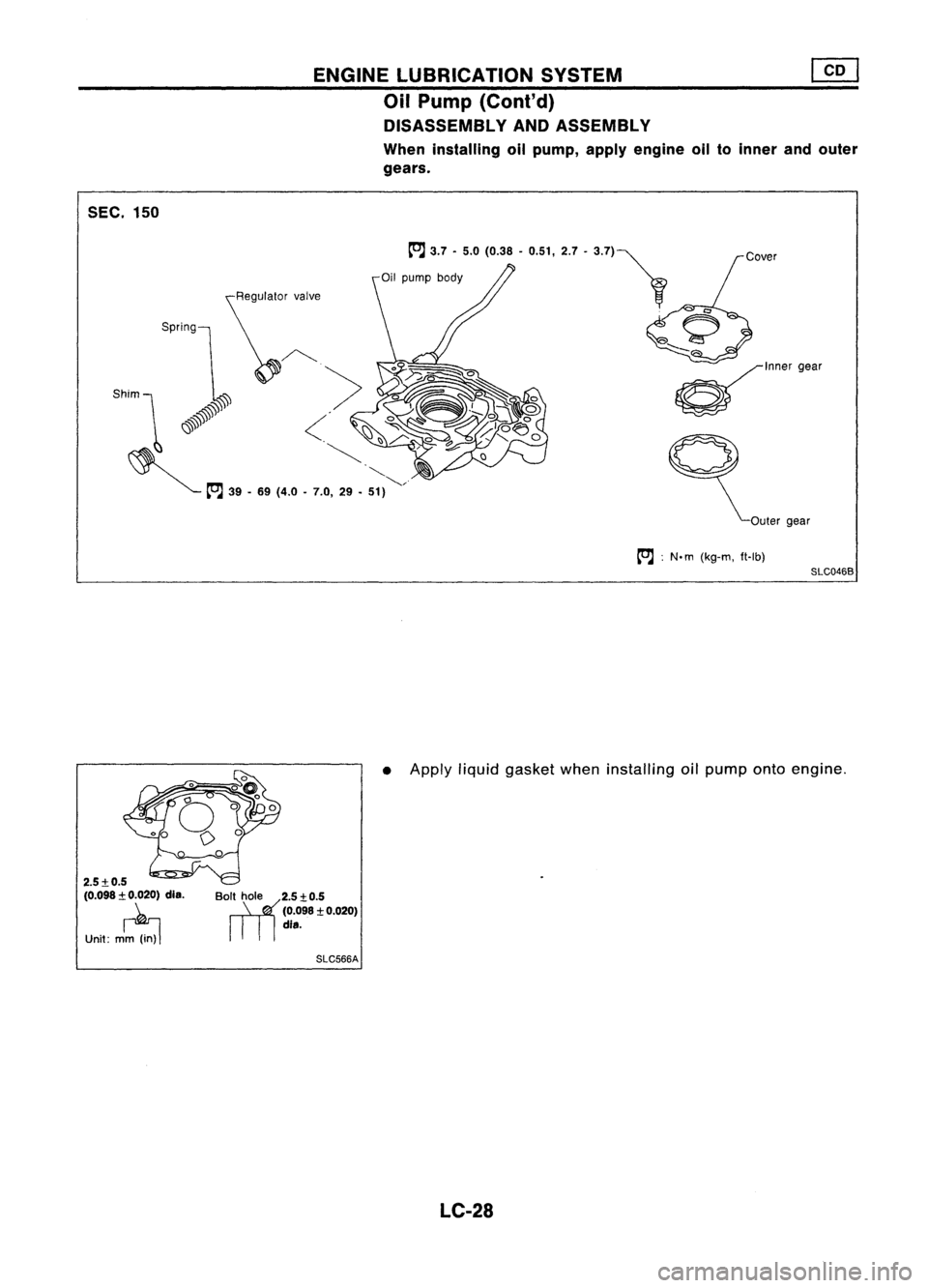
ENGINE
LUBRICATION SYSTEM
Oil Pump (Conl'd)
DISASSEMBLY ANDASSEMBLY
When installing oilpump, applyengine oiltoinner andouter
gears.
0'00"""
ct"",,,,
tt'.J :
N. m (kg-m, ft-Ib)
SlC0468
• Apply liquidgasket wheninstalling oilpump ontoengine.
BoriYl,t hole 2.5:t.O.5
(0.098
:t
0.020)
dis.
SlC566A
LC-28
Page 1167 of 1701
•
less
than 0.18(0.0071)
0.12
-0.20 (0.0047 -0.0079)
0.05 -0.09 (0.0020 -0.0035)
0.05 -0.11 (0.0020 -0.0043)
0.05 -0.09 (0.0020 -0.0035)
Body
toouter gearclearance
CD
Outer geartoinner gearclearance
@
Housing toinner gearclearance @
Housing toouter gearclearance
@
Inner geartohousing clearance @
If
itexceeds thelimit, replace gearsetorentire oilpump
assembly.
SLC560A
ENGINE
LUBRICATION SYSTEM
Oil Pump (Cont'd)
INSPECTION
Using afeeler gauge, checkthefollowing clearances.
Unit:mm(in)
SLC561C
SLC568A REGULATOR VALVEINSPECTION
1. Visually inspectcomponents forwear anddamage.
2. Check oilpressure regulator valvesliding surface andvalve
spring.
3. Coat regulator valvewithengine oil.Check that
it
falls freely
into thevalve holebyitsown weight.
If
damaged, replaceregulator valvesetoroil pump assembly.
SLC049B LC-29
Page 1168 of 1701
ENGINELUBRICATION SYSTEM
Oil Pump (Cont'd)
OIL PRESSURE RELIEFVALVEINSPECTION
Inspect oilpressure reliefvalve (indicated byarrow) for
movement, cracksandbreaks bypushing theball. Ifreplace-
ment isnecessary, removevalvebyprying itout with asuitable
tool. Install anew valve inplace bytapping it.
SLC446 OilCooler
SEC. 150-213
RHO
tOJ
16-21
(1.6. 2.1,12•15)
/
tOJ
34-44
11 ~
f:1
(3.5 -4.5, 25-33)
Front ~ LHO
:N.m (kg-m, ft-Ib)
Front
~
SLC047B
CD
Oilcooler
@
Connector
@
a-ring
@
Oilfilter bracket
@
Gasket
@
Cover
INSPECTION
1. Check oilcooler element andhousing forcracks.
2. Check coolant inletofoil cooler forclogging byblowing
through it.
Replace itifnecessary.
Oil cooler
SLC465A LC-30
Page 1169 of 1701
Oilcooler
Cold startdevice
ENGINE
COOLING SYSTEM
Cooling Circuit
_ ======
=.j
Reservoir tank
I
Oil cooler
Heater unit
~ :By-pass passage
LC-31 SLC407
•
Page 1170 of 1701

ENGINECOOLING SYSTEM
System Check
WARNING:
Never remove theradiator capwhen theengine ishot; serious
burns couldbecaused byhigh pressure fluidescaping fromthe
radiator.
Wrap athick cloth around capandcarefully loosenita quarter
turn torelease built-uppressure. Thenremove thecap com-
pletely.
CHECKING COOLINGSYSTEMHOSES
Check hosesforimproper attachment, leaks,cracks, damage,
loose connections, chafinganddeterioration.
CHECKING RADIATORCAP
To check radiator cap,apply pressure tocap with atester.
Radiator caprelief pressure:
Standard 78 -98 kPa
(0.78 -0.98 bar,0.8-1.0 kg/cm
2,
11-14 psi)
Limit 59 -98 kPa
(0.59 -0.98 bar, 0.6-1.0 kg/cm
2,
9-14 psi)
SLC613-A
Pullthenegative pressure valvetoopen
it.
Check thatitcloses
completely whenreleased.
CHECKING COOLINGSYSTEMFORLEAKS
To check forleakage, applypressure tothe cooling systemwith
a tester.
Testing pressure:
157 kPa (1.57 bar,1.6kg/cm
2,
23psi)
CAUTION:
Higher thanthespecified pressure maycause radiator damage.
SLC422A LC-32
Trending: belt, Head lamp, E211, EC-85, cooling, Fuel pressure regulato, glass

INSTAllATION
1, Before installing, removealltraces ofliquid gasket from
mating surface ofwater pumpusingascraper.
• Also remove tracesofliquid gasket f")

Drain plug
CID
Mounting")


0.12
-0.20 (0.0047 -0.0079)
0.05 -0.09 (0.0020 -0.0035)
0.05 -0.11 (0.0020 -0.0043)
0.05 -0.09 (0.0020 -0.0035)
Body
toouter gearclearance
CD
Outer geartoinner gearclear")

OIL PRESSURE RELIEFVALVEINSPECTION
Inspect oilpressure reliefvalve (indicated byarrow) for
movement, cracksandbreaks bypushing theball. Ifreplace-
ment")
