NISSAN ALMERA N15 1995 Service Manual
Manufacturer: NISSAN, Model Year: 1995, Model line: ALMERA N15, Model: NISSAN ALMERA N15 1995Pages: 1701, PDF Size: 82.27 MB
Page 1181 of 1701
CONTENTS(Conl'd.)
TIMING BELT
120
Camshaft TimingBelt 120
Injection PumpTiming Belt 124
OIL SEAL REPLACEMENT
126
CYLINDER HEAD 128
Removal 129
Disassembly 129
Inspection 130
Assembly 136
Installation 137
ENGINE REMOVAL
140
CYLINDER
BLOCK 143
Preparation 144
Disassembly 144
Inspection 145
Assembly 152
GA
SERVICE DATAANDSPECIFICATIONS
(505)
155
General Specifications ,155
Inspection andAdjustment. 156
SR
SERVICE DATAANDSPECIFICATIONS
(505)
163
General Specifications 163
Inspection andAdjustment. 163
CD
SERVICE DATAANDSPECIFICATIONS
(50S)
171
Inspection andAdjustment.. 171
Page 1182 of 1701
Innerside
SEM164F PRECAUTIONS
Parts Requiring AngularTightening
• Use anangle wrench forthe final tightening ofthe follow-
ing engine parts:
(1) Cylinder headbolts
(2) Main bearing capbolts (SRengine only)
(3) Connecting rodcap nuts (SRand CDengine)
• Donot use atorque valueforfinal tightening. •
• The torque values forthese partsareforapreliminary step.
• Ensure threadandseat surfaces areclean andcoated with
engine oil.
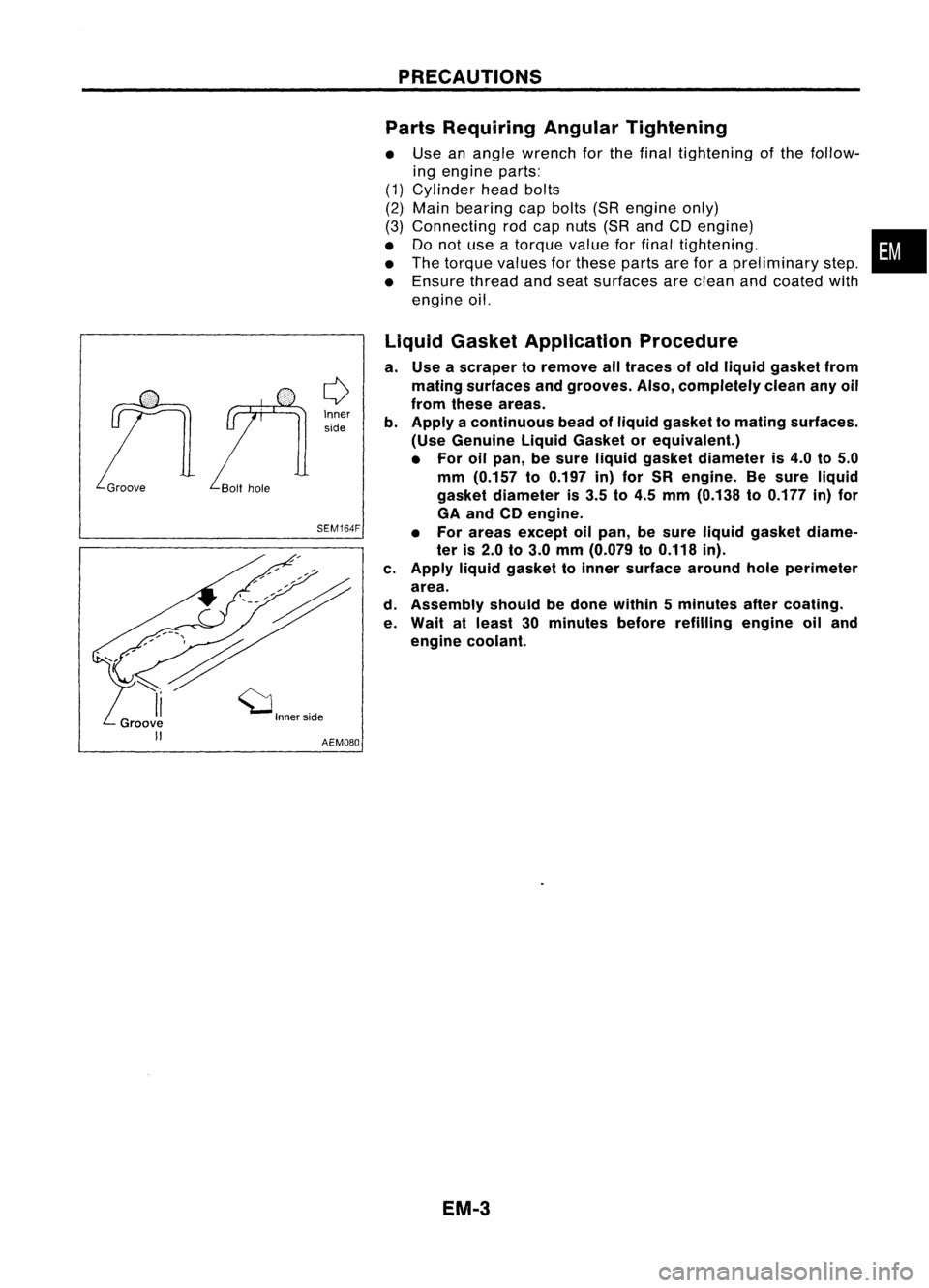
Liquid Gasket Application Procedure
a. Use ascraper toremove alltraces ofold liquid gasket from
mating surfaces andgrooves. Also,completely cleananyoil
from these areas.
b. Apply acontinuous beadofliquid gasket tomating surfaces.
(Use Genuine LiquidGasket orequivalent.)
• For oilpan, besure liquid gasket diameter is4.0 to5.0
mm (0.157 to0.197 in)for SR engine. Besure liquid
gasket diameter is3.5 to4.5 mm (0.138 to0.177 in)for
GA and CDengine.
• For areas except oilpan, besure liquid gasket diame-
ter is2.0 to3.0 mm (0.079 to0.118 in).
c. Apply liquidgasket toinner surface aroundholeperimeter
area.
d. Assembly shouldbedone within 5minutes aftercoating.
e. Wait atleast 30minutes beforerefilling engineoiland
engine coolant.
EM.3
Page 1183 of 1701
PREPARATION
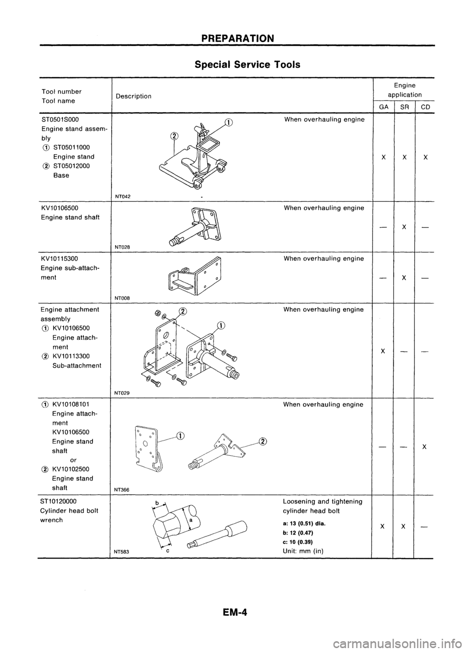
Special Service Tools
Engine
Tool number
Description application
Tool name
GA
SRCD
ST0501S000 When
overhauling engine
Engine standassem-
bly
G)
ST05011000
Engine stand
XX
X
@
ST05012000
Base
NT042
KV10106500
~
When
overhauling engine
Engine standshaft
X
NT028
KV10115300
~
When
overhauling engine
Engine sub-attach-
ment
X
NTOO8
Engine attachment When
overhauling engine
assembly
G)
KV10106500
Engine attach-
ment
X
@
KV10113300
Sub-attachment
NT029
G)
KV10108101 Whenoverhauling engine
Engine attach-
ment
KV10106500
1
~
Engine
stand
X
shaft
or
@
KV10102500
Engine stand
shaft
NT366
ST10120000
b
Loosening
andtightening
Cylinder headbolt
~~
cylinder
headbolt
wrench
a;13 (0.51) dia.
XX
b: 12 (0.47)
c: 10 (0.39)
NT583
C
Unit:mm(in)
EM.4
Page 1184 of 1701
PREPARATION
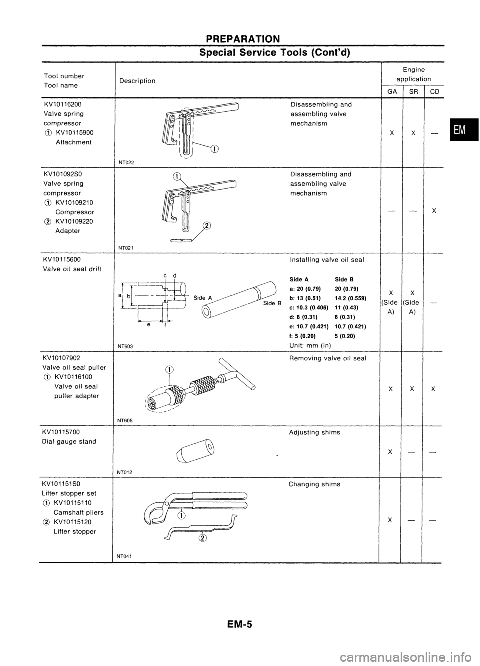
Special Service Tools(Cont'd)
Engine
Tool number
Description application
Tool name
GASRCD
KV10116200 Disassemblingand
Valve spring
assemblingvalve
compressor mechanism
•
CD
KV10115900
XX
Attachment
NT022
KV101092S0 Disassemblingand
Valve spring
assemblingvalve
compressor mechanism
0
CD
KV10109210
0
Compressor
X
@
KV10109220
Adapter
NT021
KV10115600 Installingvalveoilseal
Valve oilseal drift
c
d
SideA SideB
-HaP
a:
20 (0.79) 20(0.79)
XX
Side A
b:13 (0.51) 14.2(0.559)
(Side(Side
a
c:
10.3 (0.406)
11
(0.43)
A)A)
d: 8(0.31) 8(0.31)
e
f
e:10.7 (0.421) 10.7(0.421)
f:
5(0.20) 5(0.20)
NT603
Unit:
mm(in)
KV10107902
~
Removing
valveoilseal
Valve oilseal puller
CD
KV10116100
Valve oilseal
XXX
puller adapter
I~
\
./
'...:_.~---/
NT605
KV10115700 Adjustingshims
Dial gauge stand
0
X
NT012
KV101151 SO
Changingshims
Lifter stopper set
@t
l
:~
CD
KV10115110
Camshaft pliers
as
J
@
KV10115120
X
Lifter stopper
F
&)
NT041
EM-5
Page 1185 of 1701
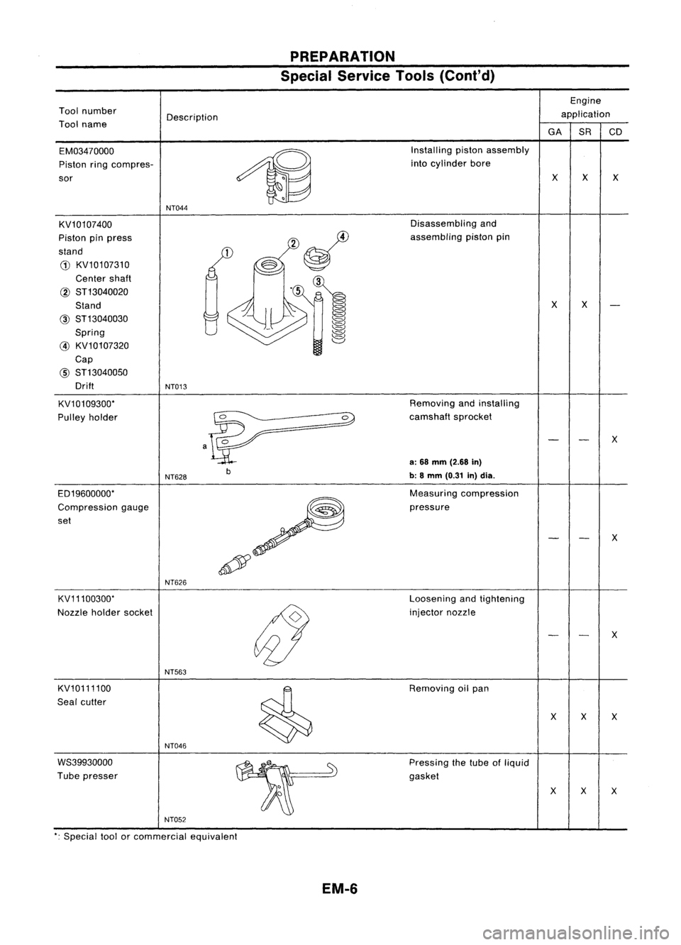
PREPARATION
Special Service Tools(Cont'd)
Engine
Tool number
Description application
Tool name
GA
SRCD
EM03470000
~
Installing
pistonassembly
Piston ringcompres- into
cylinder bore
sor
X
X
X
NT044
KV10107400 Disassembling
and
Piston pinpress assembling
pistonpin
stand
G)
KV10107310
Center shaft
@ ST13040020
Stand
X
X
@ ST13040030
Spring
@ KV10107320
Cap
@
ST13040050
Drift
NT013
KV10109300* Removing
andinstalling
Pulley holder
0
camshaftsprocket
X
a
a:
68 mm (2.68
in)
b b:8mm (0.31
in)dia.
NT628
ED19600000* Measuring
compression
Compression gauge pressure
set
X
p'
NT626
KV11100300* Loosening
andtightening
Nozzle holdersocket
(J
injector
nozzle
X
NT563
KV10111100
~
Removing
oilpan
Seal cutter
X
X
X
NT046
WS39930000 Pressingthetube ofliquid
Tube presser gasket
XXX
NT052
*: Special toolorcommercial equivalent
EM-6
Page 1186 of 1701
Toolnumber
Tool name Description
PREPARATION
Special Service Tools(Cont'd)
Engine
application
GA SRCD
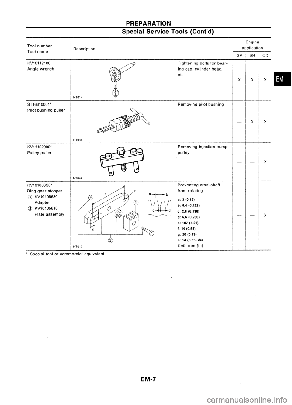
KV10112100
Angle wrench
ST16610001*
Pilot bushing puller
KV11102900*
Pulley puller
KV101056S0*
Ring gear stopper
G) KV10105630
Adapter
@ KV10105610
Plate assembly
NT014
NT045
NT647
NT617
Tightening
boltsforbear-
ing cap, cylinder head,
etc.
Removing pilotbushing
Removing injectionpump
pulley
Preventing crankshaft
from rotating
a:
3(0.12)
b: 6.4 (0.252)
c:
2.8 (0.110)
d: 6.6 (0.260)
e:
107 (4.21)
f:
14 (0.55)
g:
20 (0.79)
h: 14 (0.55) dia.
Unit: mm(in)
x
x
x
X
X
x
*:
Special toolorcommercial equivalent
EM-7
Page 1187 of 1701
PREPARATION
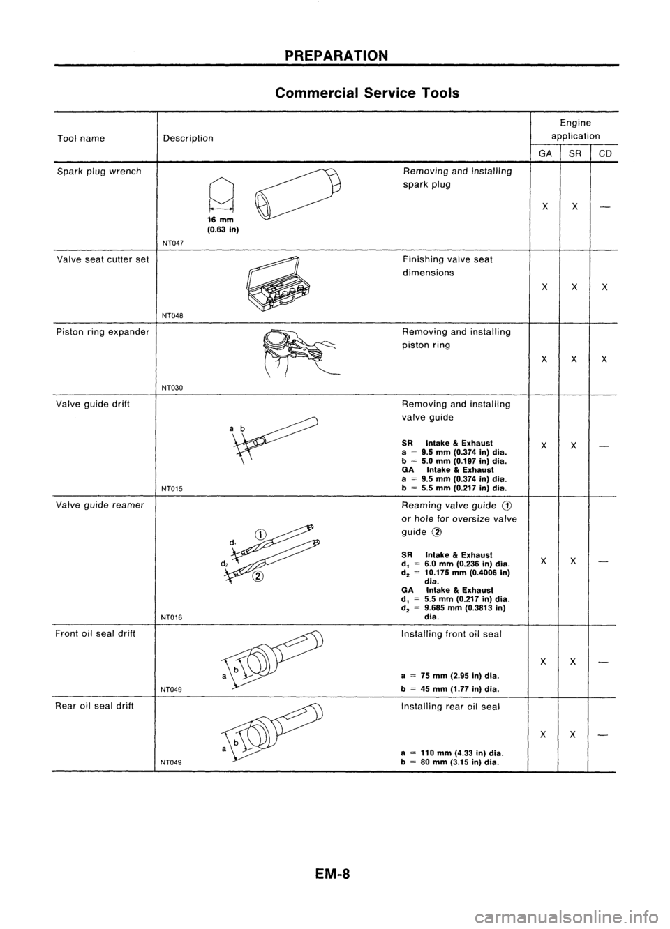
Commercial ServiceTools
Engine
Tool name Description application
GA
SRCD
Spark plugwrench
0
Removing
andinstalling
Q
spark
plug
XX
16
mm
(0.63
In)
NT047
Valve seatcutter set
~
Finishing
valveseat
dimensions
XX
X
NT048
Piston ringexpander
~
Removing
andinstalling
piston ring
X
X
X
NT030
Valve guidedrift Removingandinstalling
'~
valve
guide
SR
Intake
&
Exhaust
XX
a
=
9.5
mm
(0.374 in)dia.
b
=
5.0
mm
(0.197 in)dia.
GA
Inlake
&
Exhaust
a
=
9.5
mm
(0.374 In)dla.
NT015
b
=
5.5
mm
(0.217 in)dla.
Valve guide reamer
Reaming
valve
guide
G)
or hole foroversize valve
~
guide
@
d,
\J
SR
Intake
&
Exhausl
XX
d,
=
6.0
mm
(0.236 in)dia.
@
d,
=
10.175
mm
(0.4006 in)
dia.
GA
Intake
&
Exhausl
d,
=
5.5
mm
(0.217 in)dia.
d,
=
9.685
mm
(0.3813 in)
NT016
dia.
Front oilseal drift
Installingfrontoilseal
XX
a
=
75
mm
(2.95 In)dla.
NT049
b
=
45
mm
(1.77 in)dia.
Rear oilseal drift
Installingrearoilseal
X
X
a
=
110
mm
(4.33 In)dla.
NT049
b
=
80
mm
(3.15 in)dia.
EM-8
Page 1188 of 1701
![NISSAN ALMERA N15 1995 Service Manual OUTERCOMPONENT PARTS
GA16DE WITHOUT VTC,14DE AND15DE
~ 15.7 •
20.6 (1.60 •2.10,11.58 -
15.19)
SEC.
140.150.210.211.220.221.253
•
l
-Q;Jj
Si ""~
/4J
0/)'
~ff?~~
1ii] •.
28 NISSAN ALMERA N15 1995 Service Manual OUTERCOMPONENT PARTS
GA16DE WITHOUT VTC,14DE AND15DE
~ 15.7 •
20.6 (1.60 •2.10,11.58 -
15.19)
SEC.
140.150.210.211.220.221.253
•
l
-Q;Jj
Si ""~
/4J
0/)'
~ff?~~
1ii] •.
28](/img/5/57349/w960_57349-1187.png)
OUTERCOMPONENT PARTS
GA16DE WITHOUT VTC,14DE AND15DE
~ 15.7 •
20.6 (1.60 •2.10,11.58 -
15.19)
SEC.
140.150.210.211.220.221.253
•
l
-Q;Jj
Si ""~
/4J
0/)'
~ff?~~
1ii] •.
28 •'.34 '0.'" •0.851, 55.'•73.9) /
ijJ
'.28 -'.34 (0.'" •0.851, 55.'•73.9)
CIDco:J
19.6•29.4
(2.00 .3.00,
14.46•21.69)~
[jJ :
N.m (kg-m, in-Ib)
~ :N.m (kg-m, fHb)
~ :Apply
liquidgasket.
SEM060FA
G)
Oilpressure switch
@
Distributor
@
Spark plug
@
Thermal transmitter
@
Intake manifold
@
Intake manifold supports
(J)
OiIfilter
@
Thermostat
@
Water pump
EM-9
Page 1189 of 1701
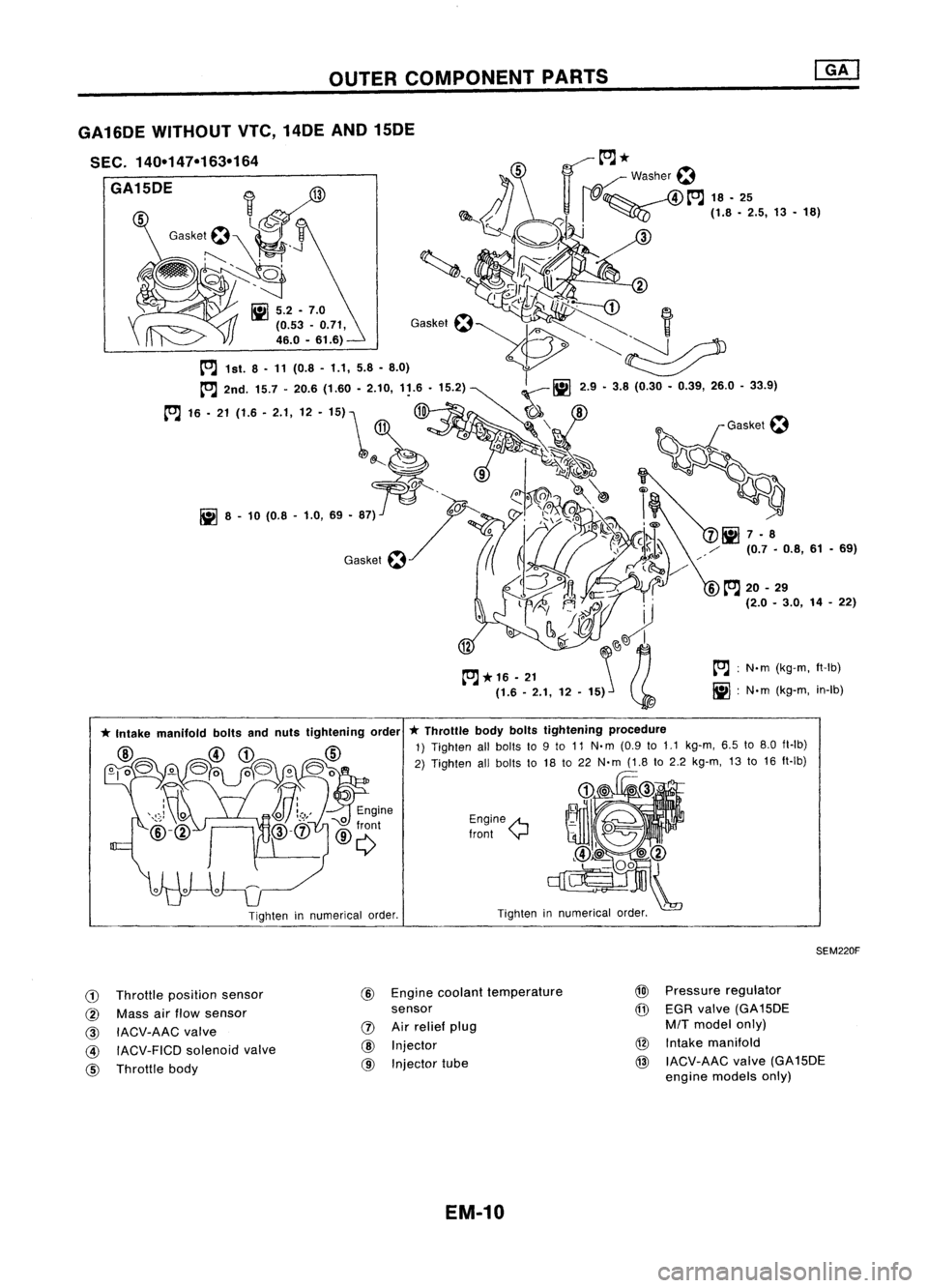
OUTERCOMPONENT PARTS
tOJ:
N.m (kg-m, ft-Ib)
iii :
N'm (kg-m, in-Ib)
Tighten innumerical order.
Engine
A
Iront
y
*
Throttle bodyboltstightening procedure
1) Tighten allbolts to9to 11 N.m (0.9 to
1.1
kg-m, 6.5to8.0 fl-Ib)
2) Tighten allbolts to18 to22 N'm (1.8to2.2 kg-m, 13to16 ft-Ib)
Tighten innumerical order.
GA16DE
WITHOUT VTe,14DE AND15DE
SEC. 140-147-163-164
GA15DE
SEM220F
CD
Throttle position sensor
@ Mass airflow sensor
@
IACV-AAC valve
@ IACV-FICD solenoidvalve
@ Throttle body @
Engine coolant temperature
sensor
IJ)
Airrelief plug
@
Injector
@ Injector tube
@l
Pressure regulator
@
EGR valve (GA15DE
M/T
model only)
@ Intake manifold
@ IACV-AAC valve(GA15DE
engine models only)
EM-10
Page 1190 of 1701
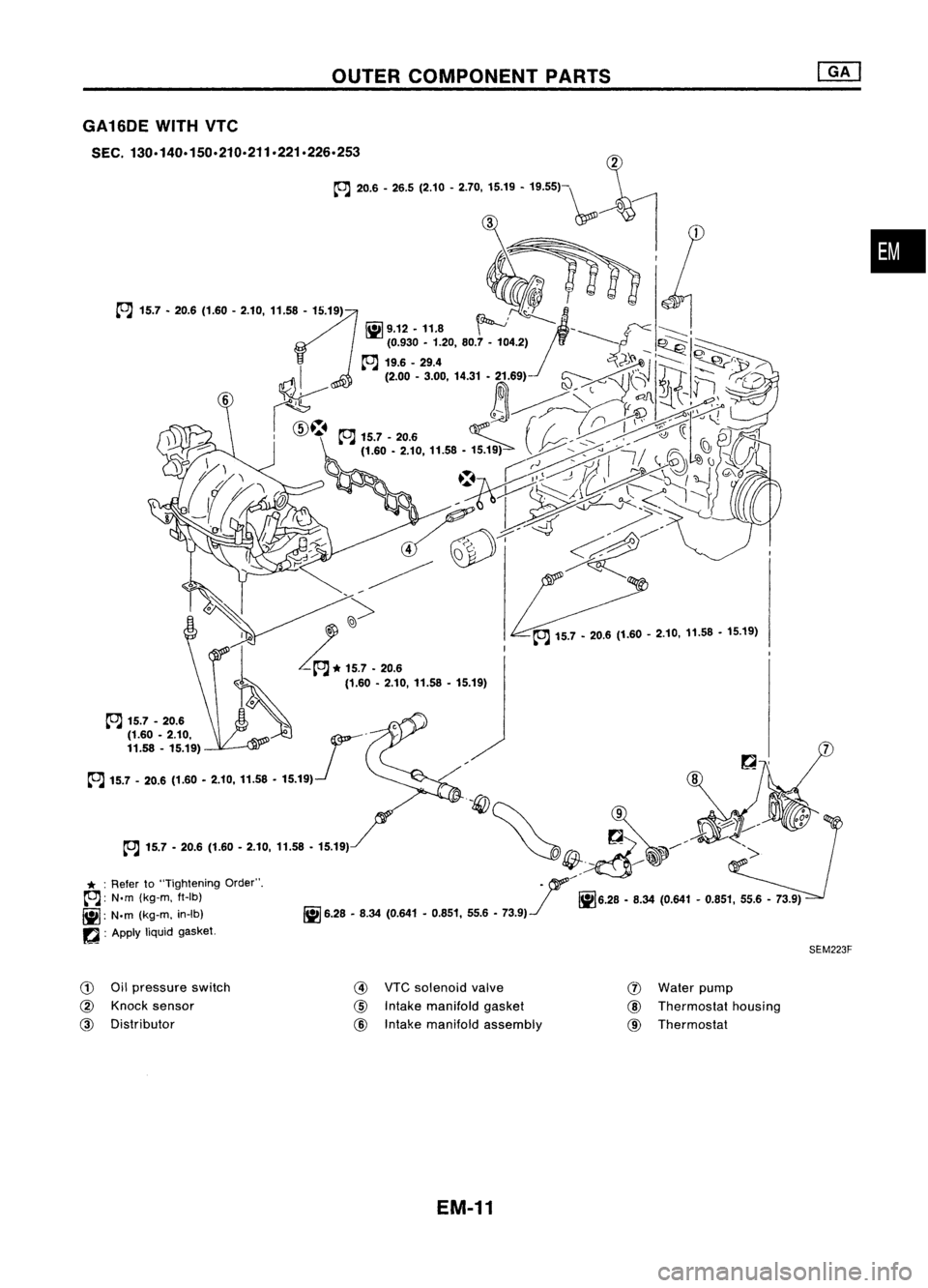
OUTERCOMPONENT PARTS
COJ
15.7 -20.6 (1.60 -2.10, 11.58 -15.19)
•
7
SEM223F
~
9 -
~~~/~ ->
. f'
!il6.28 _8.34 (0.641 -0.851, 55.6-73.9)
~ 6.28.8.34 (0.641-0.851, 55.6-
73.9)-.1
COJ
15.7 -20.6
* :
Refer to"Tightening Order".
~: N.m(kg-m. ft-Ib)
~: N.m(kg-m. in-Ib)
~ :Apply
liquidgasket.
GA16DE
WITHVTC
SEC.
130.140.150.210.211.221.226.253 ~
~ ,... -26.5
{2.1' -'.70,
:5.19 _19.5Sl-\,,4
r
G)
Oilpressure switch
@ Knock sensor
@
Distributor
@
VTCsolenoid valve
@
Intake manifold gasket
@
Intake manifold assembly
(J)
Water pump
@
Thermostat housing
@
Thermostat
EM-11