NISSAN ALMERA N15 1995 Service Manual
Manufacturer: NISSAN, Model Year: 1995, Model line: ALMERA N15, Model: NISSAN ALMERA N15 1995Pages: 1701, PDF Size: 82.27 MB
Page 1411 of 1701
Open
Close
AIC
service valve
Counterclockwise
Clockwise
Shut
offvalve rotation
Never
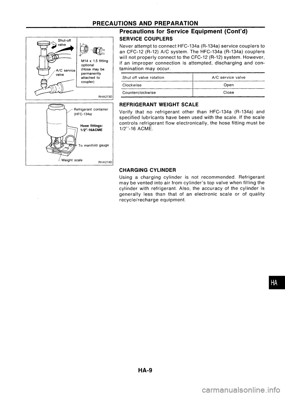
attempt toconnect HFC-134a (R-134a)servicecouplers to
an CFC-12 (R-12)
A/C
system. TheHFC-134a (R-134a)couplers
will notproperly connecttothe CFC-12 (R-12)system. However,
if an improper connection isattempted, discharging andcon-
tamination mayoccur.
REFRIGERANT WEIGHTSCALE
Verify thatnorefrigerant otherthanHFC-134a (R-134a)and
specified lubricants havebeenusedwiththescale. Ifthe scale
controls refrigerant flowelectronically, thehose fitting mustbe
1/2"-16 ACME.
RHA274D
PRECAUTIONS
ANDPREPARATION
Precautions forService Equipment (Cont'd)
SERVICE COUPLERS
RHA273D
M14
x
1.5 fitting
optional (Hose maybe
permanently
attached to
coupler)
Hose fittings:
1/2"-16ACME
To manifold gauge
CHARGING CYLINDER
Using acharging cylinderisnot recommended. Refrigerant
may bevented intoairfrom cylinder's topvalve whenfilling the
cylinder withrefrigerant. Also,theaccuracy ofthe cylinder is
generally lessthan thatofan electronic scaleorofquality
recycle/recharge equipment.
•
HA-9
Page 1412 of 1701
DESCRIPTION
Refrigeration Cycle
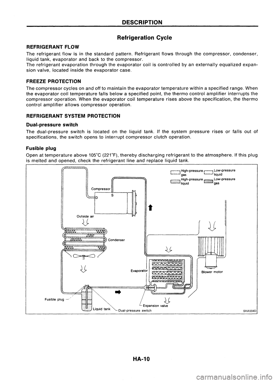
REFRIGERANT FLOW
The refrigerant flowisinthe standard pattern.Refrigerant flowsthrough thecompressor, condenser,
liquid tank,evaporator andback tothe compressor.
The refrigerant evaporation throughtheevaporator coiliscontrolled byan externally equalizedexpan-
sion valve, located insidetheevaporator case.
FREEZE PROTECTION
The compressor cyclesonand offtomaintain theevaporator temperature withinaspecified range.When
the evaporator coiltemperature fallsbelow aspecified point,thethermo controlamplifier interrupts the
compressor operation.Whentheevaporator coiltemperature risesabove thespecification, thethermo
control amplifier allowscompressor operation.
REFRIGERANT SYSTEMPROTECTION
Dual-pressure switch
The dual-pressure switchislocated onthe liquid tank.Ifthe system pressure risesorfalls outof
specifications, theswitch openstointerrupt compressor clutchoperation.
Fusible plug
Open attemperature above105°C(221°F), thereby discharging refrigeranttothe atmosphere. Ifthis plug
is melted andopened, checktherefrigerant lineand replace liquidtank.
c:::::.J
High-pressure
EJ
Low-pressure
gas liquid
1:-:-:-:-::-:-::-:-:1
~~~~pressure
!::i'i'i':}':J
~~:-pressure
Compressor
D
Outside air
U
s
t
Fusible plug-~
~..
U
'" Expansionvalve
Liquid tank"'--Dual-pressure switch
HA-10
Blower
motor
SHA504D
Page 1413 of 1701

270-271-272-273
SEC.
tnozzle
Side defros er
__________
~==D=ES=C~R~I~P~TI~O~N~~---------
Component Layout
Defroster nozzle
Sidedefroster nozzle
.1 tor duct
Side venlia Center
ventilator duct
Control assembly Side
ventilator duct
Cooling unit
•
D models. ositetothis layout.
.
.11 stration isfor
LH .
symmetrically opp
This
I
u RHOmodels
IS
The layout for
RHA312F
HA-11
Page 1414 of 1701
DESCRIPTION
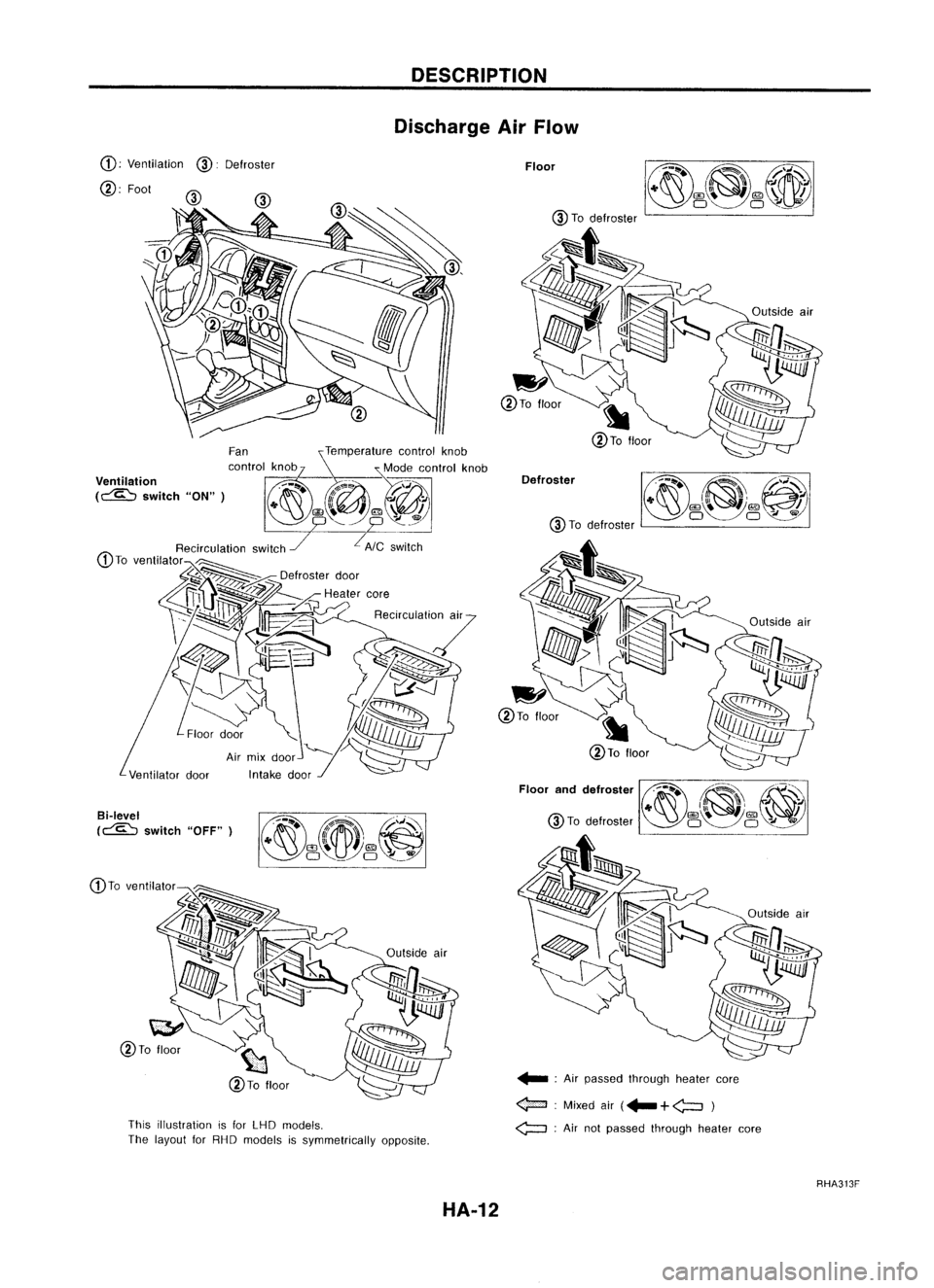
Discharge AirFlow
@ Todefroster
Floor
Defroster
.... ;Air passed through heatercore
<$=::I :
Mixed air(...
+
<;::::J )
<:;:::::J ;
Air not passed through heatercore
This
illustration isfor LHD models.
The layout forRHD models issymmetrically opposite.
Ventilator
door
CD;
Ventilation
@:
Defroster
@; Fool
Bi-Ievel
(~ switch"OFF")
RHA313F
HA-12
Page 1415 of 1701
DESCRIPTION
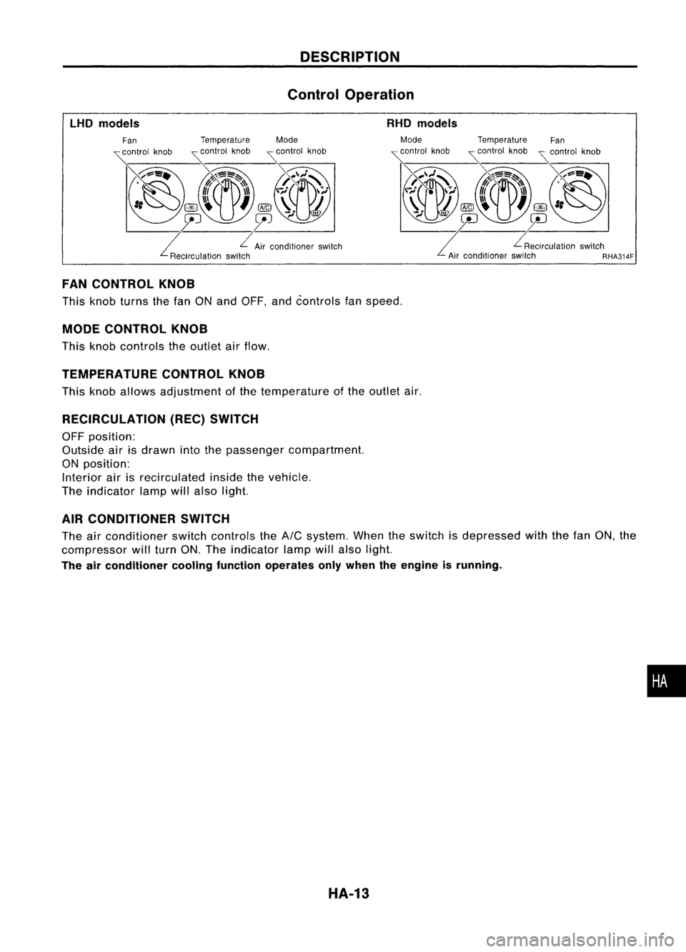
Control Operation
LHO models RHO
models
FAN CONTROL KNOB
This knob turns thefan ONand OFF, andcontrols fanspeed.
MODE CONTROL KNOB
This knob controls theoutlet airflow.
TEMPERATURE CONTROLKNOB
This knob allows adjustment ofthe temperature ofthe outlet air.
RECIRCULATION (REC)SWITCH
OFF position:
Outside airisdrawn intothepassenger compartment.
ON position:
Interior airisrecirculated insidethevehicle.
The indicator lampwillalso light.
AIR CONDITIONER SWITCH
The airconditioner switchcontrols the
Ale
system. Whentheswitch isdepressed withthefan ON, the
compressor willturn ON.The indicator lampwillalso light.
The airconditioner coolingfunction operates onlywhen theengine isrunning.
HA-13
•
Page 1416 of 1701
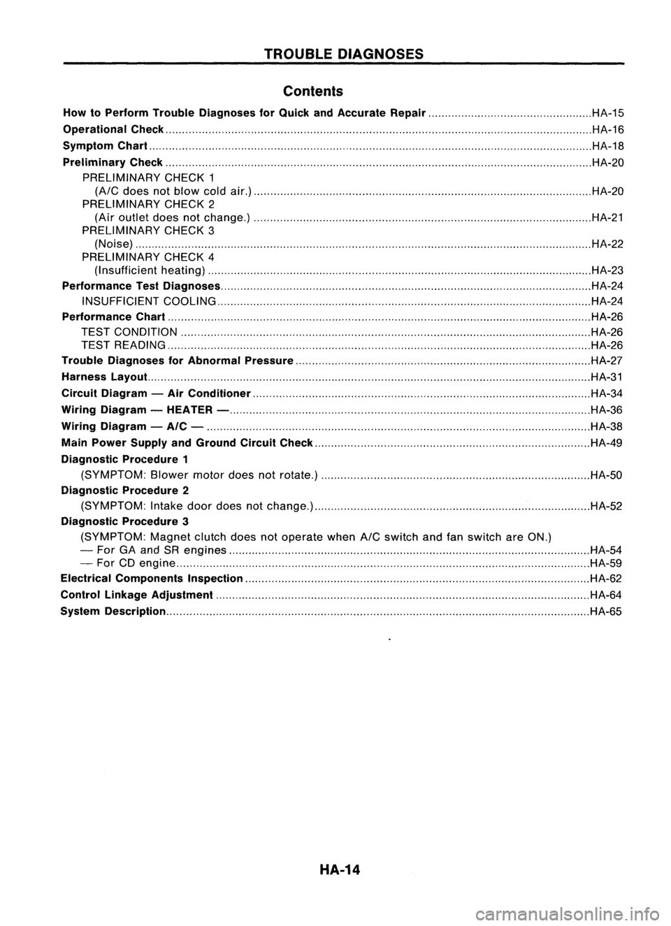
TROUBLEDIAGNOSES
Contents
How toPerform TroubleDiagnoses forQuick andAccurate Repair HA-15
Operational Check HA-16
Symptom Chart HA-18
Preliminary Check HA-20
PRELIMINARY CHECK1
(A/C
does notblow coldair.) HA-20
PRELIMINARY CHECK2
(Air outlet doesnotchange.) HA-21
PRELIMINARY CHECK3
(Noise) HA-22
PRELIMINARY CHECK4
(I nsufficient heating) HA-23
Performance TestDiagnoses HA-24
INSUFFICIENT COOLING HA-24
Performance Chart HA-26
TEST CONDITION HA-26
TEST READING HA-26
Trouble Diagnoses forAbnormal Pressure HA-27
Harness Layout. HA-31
Circuit Diagram -Air Conditioner HA-34
Wiring Diagram -HEATER - HA-36
Wiring Diagram -AIC - HA-38
Main Power Supply andGround CircuitCheck HA-49
Diagnostic Procedure1
(SYMPTOM: Blowermotordoesnotrotate.) HA-50
Diagnostic Procedure2
(SYMPTOM: Intake doordoes notchange.) HA-52
Diagnostic Procedure3
(SYMPTOM: Magnetclutchdoesnotoperate when
A/C
switch andfanswitch areON.)
- For GAand SRengines HA-54
- For CDengine HA-59
Electrical Components Inspection HA-62
Control Linkage Adjustment HA-64
System Description HA-65
HA-14
Page 1417 of 1701
TROUBLEDIAGNOSES
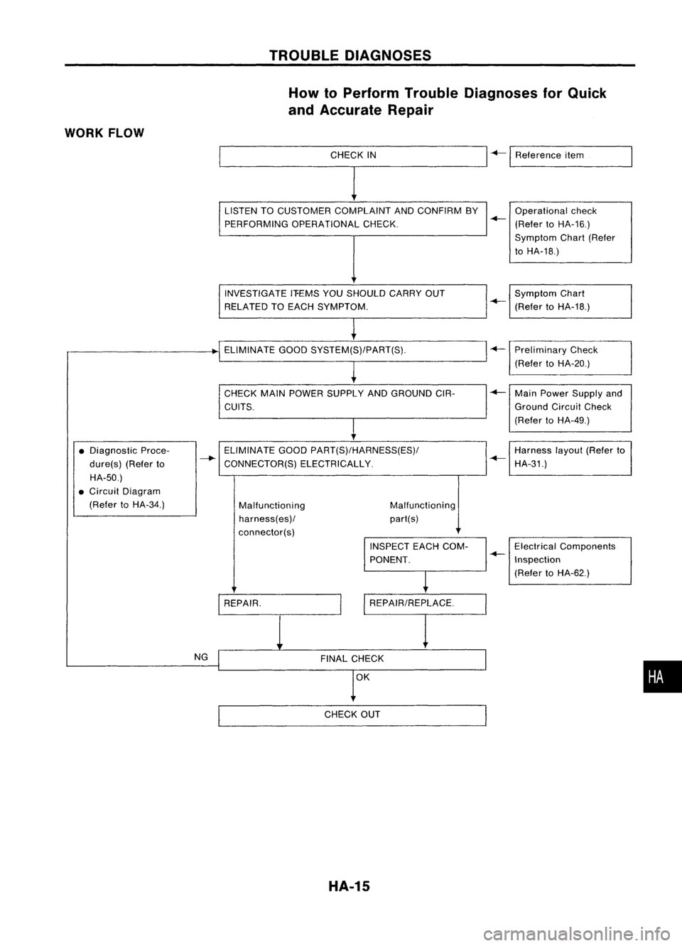
How toPerform TroubleDiagnoses forQuick
and Accurate Repair
WORK FLOW
_________C_H_EI_K_I_N
I
+-1
Reference item
.--------------,
ELIMINATE GOODSYSTEM(S)/PART(S).
INVESTIGATE
IT-EMSYOUSHOULD CARRYOUT
RELATED TOEACH SYMPTOM.
CHECK MAINPOWER SUPPLY ANDGROUND CIR-
CUITS. LISTEN
TOCUSTOMER COMPLAINT ANDCONFIRM BY
PERFORMING OPERATIONAL CHECK. Operational
check
+-
(Refer toHA-16.)
Symptom Chart(Refer
to HA-18.)
Symptom Chart
+-
(Refer toHA-18.)
+-
Preliminary Check
(Refer toHA-20.)
+-
MainPower Supply and
Ground CircuitCheck
(Refer toHA-49.)
Harness layout(Referto
+-
HA-31.)
Malfunctioning
part(s)
Malfunctioning
harness( es)/
connector(s)
ELIMINATE
GOODPART(S)/HARNESS(ES)/
CONNECTOR(S) ELECTRICALLY.
•
Diagnostic Proce-
dure(s) (Referto
HA-50.)
• Circuit Diagram
(Refer toHA-34.)
NG
I
REPAIR. INSPECT
EACHCOM-
PONENT.
FINAL CHECK Electrical
Components
+-
Inspection
(Refer toHA-62.)
•
CHECK OUT
HA-15
Page 1418 of 1701
TROUBLEDIAGNOSES
Operational Check
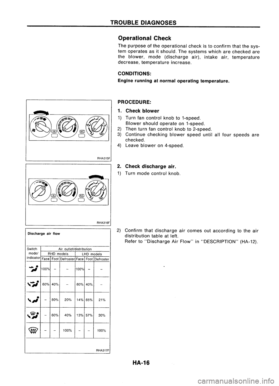
The purpose ofthe operational checkisto confirm thatthesys-
tem operates asitshould. Thesystems whicharechecked are
the blower, mode(discharge air),intake air,temperature
decrease, temperature increase.
CONDITIONS:
Engine running atnormal operating temperature.
RHA315F
RHA316F
Discharge airflow
Switch Airoutlet/distribution
model RHDmodels
LHDmodels
indicator FaceFootDefroster FaceFoot
Defroster
_e
100% 100%
II
-
- -
-
"#Ie
60%
40%
-
60%
40%
-
"J
-
80%
20%14%
65% 21%
,,
60% 40%
13%57%
30%
W
-
-
100%
-
-
100%
RHA317F PROCEDURE:
1. Check blower
1) Turn fancontrol knobto1-speed.
Blower shouldoperate on1-speed.
2) Then turnfancontrol knobto2-speed.
3) Continue checking blowerspeeduntilallfour speeds are
checked.
4) Leave blower on4-speed.
2. Check discharge air.
1) Turn mode control knob.
2) Confirm thatdischarge aircomes outaccording tothe air
distribution tableatleft.
Refer to"Discharge AirFlow" in"DESCRIPTION" (HA-12).
HA-16
Page 1419 of 1701
RHA318F
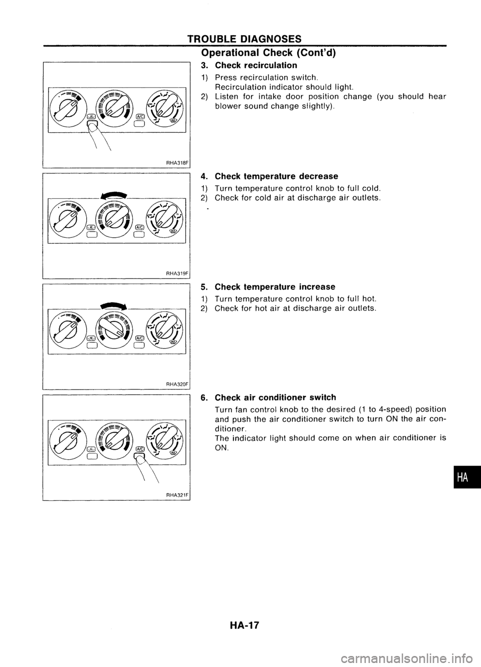
4.Check temperature decrease
~~ ~~~nC~ef~~~~~~ur~ cont:olknobtofull cold.
air atdischarge airoutlets.
TROUBLE
DIAGNOSES
Operational Check(Cont'd)
3. Check recirculation
1) Pre~s recirculation switch.
2) ~.eclrculati~n indicatorshouldlight
Isten forIntake doorposition ch'an
blower soundchange slightly). ge(you should hear
RHA319F
5.Check temperature increase
~~ ~~rn ~efmperatu:e controlknobtofull hot
ec orhot airatdischarge airoutlets:
RHA320F
6.Check airconditioner switch
Turn fancontrol knobtothe desired 1
a~? push theairconditioner 'th (to 4-speed) position
dltlOner.
SWI
ctoturn ONtheaircon-
The indicator lightshould com .
ON. eon when airconditioner is
•
RHA321F
HA-17
Page 1420 of 1701
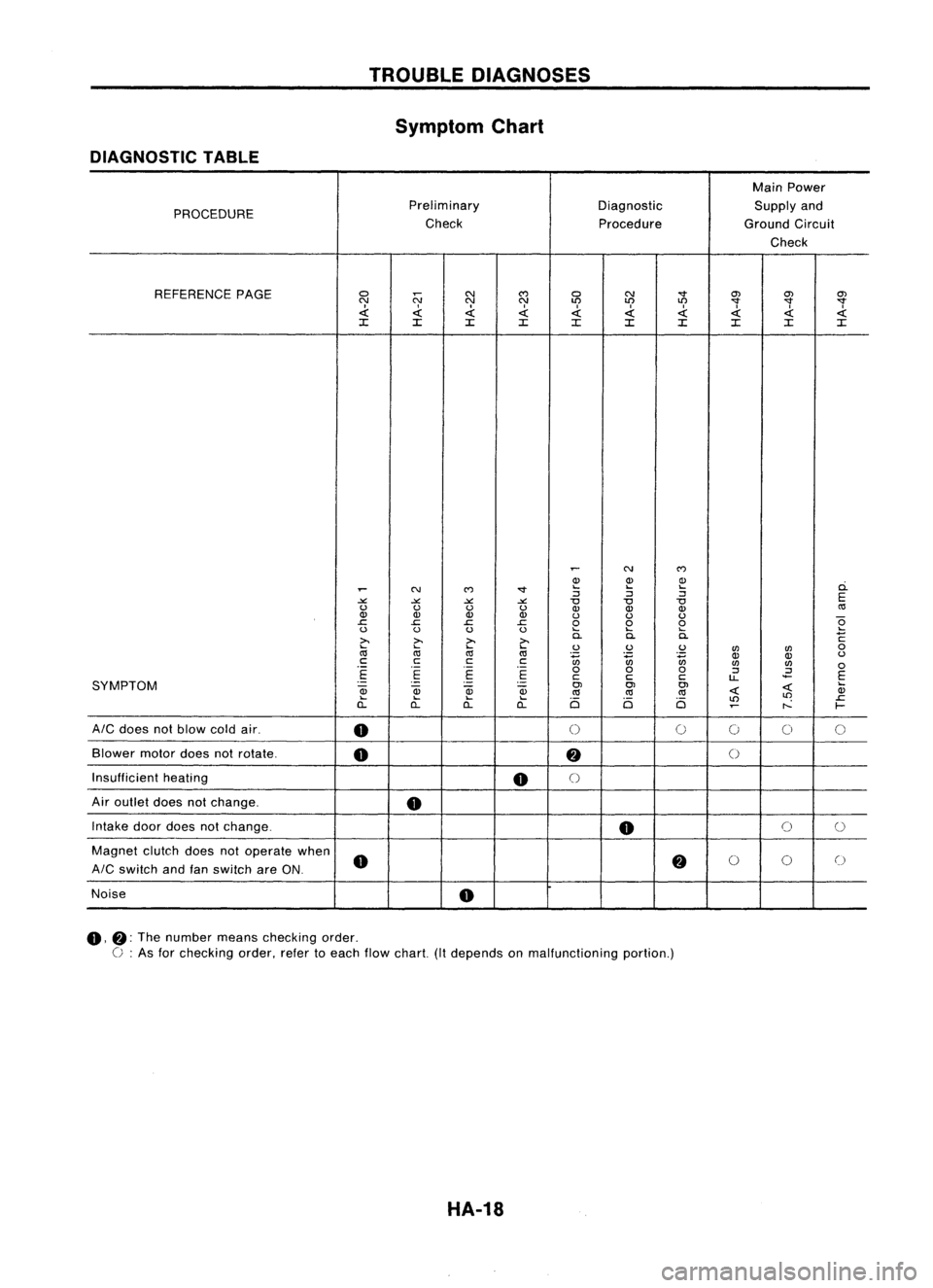
TROUBLEDIAGNOSES
Symptom Chart
DIAGNOSTIC TABLE
MainPower
PROCEDURE Preliminary
DiagnosticSupplyand
Check ProcedureGroundCircuit
Check
REFERENCE PAGE
0
N
N
C')
0 N
"'"
O'J
O'JO'J
N NN
LO LO
LO
"'""'""'"
.d: .d:.d: .d:.d:
I
.d: .d:.d:
.d:
~
:c :c:c :c
:c :c:c :c:c:c
~
N
C')
Q) Q)Q)
ci.
~
N
C')
"'" ....
....
....
:J :J:J
E
-'" -'"-'" -'"
"0
"0"0
u uu u
Q)Q) Q)
«l
Q) Q)Q) Q)
uuu
e
.c
.c.c .c
000
u uu u
....
........
>.
~
>.
>.
0.
0.0.
C
~
....
....
uu u
UJ UJ
0
«l «l
«l
~ ~~
OJ
Q)
u
c cc
c
UJUJ
0
.-
.-
.-
000
:J
.2
E E
E E
ccc
u..
E
SYMPTOM
.-
-
.
-
OJOJOJ
~
....
~
OJ
Qj
Qj
«l«l
«l
~ Q)
.... .... ....
Ci Ci Ci
LO
LO
.c
a.. a..a..
a..
~
r--
f-
AIC
does notblow coldair.
0
0
0
0
00
Blower motordoesnotrotate.
0
fj
()
Insufficient heating
0
()
Air outlet doesnotchange.
0
Intake doordoes notchange.
0
0
0
Magnet clutchdoesnotoperate when
0
fj
0
0
0
AIC
switch andfanswitch areON.
Noise
0
0,
fj:
The number meanschecking order.
C :
As for checking order,refertoeach flowchart. (Itdepends onmalfunctioning portion.)
HA-18