NISSAN ALMERA N15 1995 Service Manual
Manufacturer: NISSAN, Model Year: 1995, Model line: ALMERA N15, Model: NISSAN ALMERA N15 1995Pages: 1701, PDF Size: 82.27 MB
Page 1421 of 1701
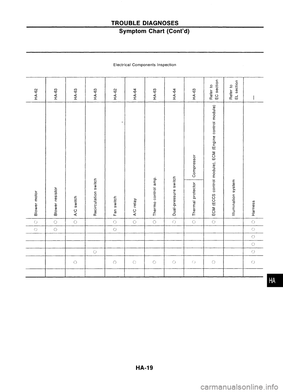
TROUBLEDIAGNOSES
Symptom Chart(Cont'd)
Electrical Components Inspection
cc
0
.Q
.8
on
.8
tl
C\J
C')
C')C')
C\J-.r
C')
-.r
C')
....
Q)
....
Q)
CD CD
CDCD
CDCD CDCD
CD
Q)
CfJ
Q)
CfJ
Qj
«
0-l
I
I
I IIII III
a::
w
a::
w
Q)
:J
"'0
0
E
.
~
c
0
(.)
Q)
c
Ol
c
~
....
~
0
0
CfJ
W
CfJ
Q) Q)
....
a.
:J
E
"'0
0
0
ci.
r.
0
E
r.
.B
E
.B
E
.~
....
~
.~
crl
0
C Q)
....
-
CfJ
tl
tl
0
CfJ
0
Q) Q)
0
>.
.... ....
(.)
CfJ
0
~
c
C
....
(5
(5
0
:J
....
(/J
c
CfJ
r.
:;
r.
0
CfJ
a.
0
0
E
Q)
.B .B
>.
(.)
CfJ
0
.~
....
crl
Q)
Ci3
CfJ
.... ....
.~
:J
.~
OJ
0
....
w
CfJ
Q) Q)
~
E
9-
E
c
Q)
CfJ CfJ
....
~ ~
....
Ci3
~
E
c
0
(.)
c
0
Q)
Q)
....
0
0
OJ
crl
r.
:J
r.
0
:J
crl
iii iii
;;:
;;:
-
a::
LL
I-
0
I-
W
-
I
-
()
0 0
0
0
0
()
00
0
0
0
0
()
0 0
()
0
0 0
(::
0
()
(0)
() ()
HA-19
•
Page 1422 of 1701
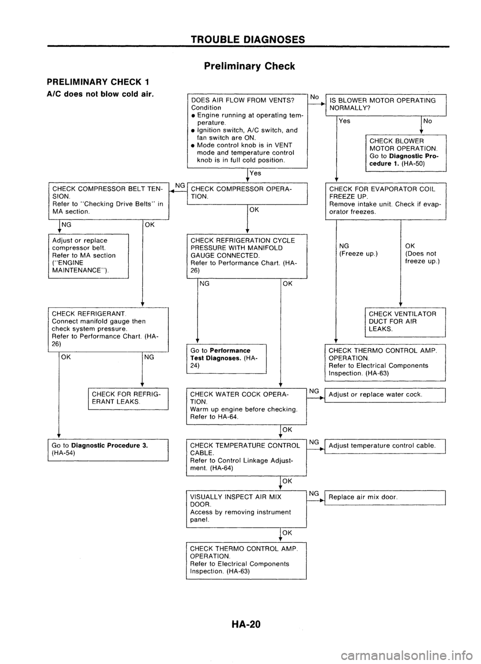
TROUBLEDIAGNOSES
Preliminary Check
PRELIMINARY CHECK1
Ale
does notblow coldair.
DOESAIRFLOW FROM VENTS?
Condition
• Engine running atoperating tem-
perature .
• Ignition switch,AICswitch, and
fan switch areON.
• Mode control knobisin VENT
mode andtemperature control
knob isinfull cold position.
Yes IS
BLOWER MOTOROPERATING
NORMALLY?
Yes
CHECKBLOWER
MOTOR OPERATION.
Go toDiagnostic Pro-
cedure 1.(HA-50)
CHECK COMPRESSOR BELTTEN-
SION. Refer to"Checking DriveBelts" in
MA section.
CHECK REFRIGERANT.
Connect manifold gaugethen
check system pressure.
Refer toPerformance Chart.(HA-
26)
NG CHECK
THERMO CONTROL AMP.
OPERATION.
Refer toElectrical Components
Inspection. (HA-63)
CHECK
FOREVAPORATOR COIL
FREEZE UP.
Remove intakeunit.Check ifevap-
orator freezes.
NG OK
(Freeze up.) (Doesnot
freeze up.)
CHECK VENTILATOR
DUCT FORAIR
LEAKS.
OK
Go toPerformance
Test Diagnoses. (HA-
24)
NG
CHECK
REFRIGERATION CYCLE
PRESSURE WITHMANIFOLD
GAUGE CONNECTED.
Refer toPerformance Chart.(HA-
26) OK
CHECK
COMPRESSOR OPERA-
TION.
OK
OK NG
Adjust orreplace
compressor belt.
Refer toMA section
("ENGINE
MAINTENANCE").
CHECKFORREFRIG-
ERANT LEAKS CHECK
WATER COCKOPERA-
TION.
Warm upengine beforechecking.
Refer toHA-64.
NG
Adjust orreplace watercock.
OK
Go toDiagnostic Procedure3.
(HA-54) CHECK
TEMPERATURE CONTROL
CABLE.
Refer toControl Linkage Adjust-
ment. (HA-64) NG
Adjust temperature controlcable.
OK
VISUALLY INSPECTAIRMIX
DOOR.
Access byremoving instrument
panel. NG
Replace airmix door.
OK
CHECK THERMO CONTROL AMP.
OPERATION. Refer toElectrical Components
Inspection. (HA-63)
HA-20
Page 1423 of 1701
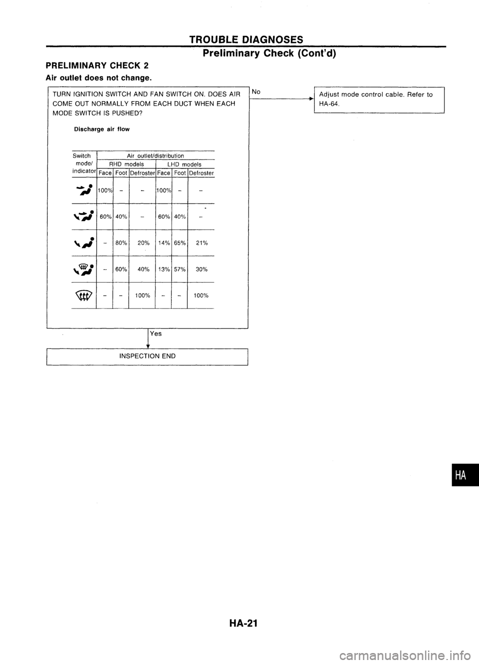
PRELIMINARY CHECK2
Air outlet doesnotchange. TROUBLE
DIAGNOSES
Preliminary Check(Cont'd)
TURN IGNITION SWITCHANDFANSWITCH ON.DOES AIR No
Adjustmodecontrol cable.Referto
COME OUTNORMALLY FROMEACHDUCTWHEN EACH HA-64.
MODE SWITCH ISPUSHED?
Discharge airflow
Switch Airoutlet/distribution
model RHOmodels
LHDmodels
indicator FaceFoot
Defroster FaceFoot
Defroster
iI
100%
-
-
100%
-
-
.
,7,./
60%40%
-
60%40%
-
,~
-
80%
20%14%65% 21%
,~
-
60% 40%
13%57% 30%
\tEl
-
-
100%
-
-
100%
res
INSPECTION END
HA-21
•
Page 1424 of 1701
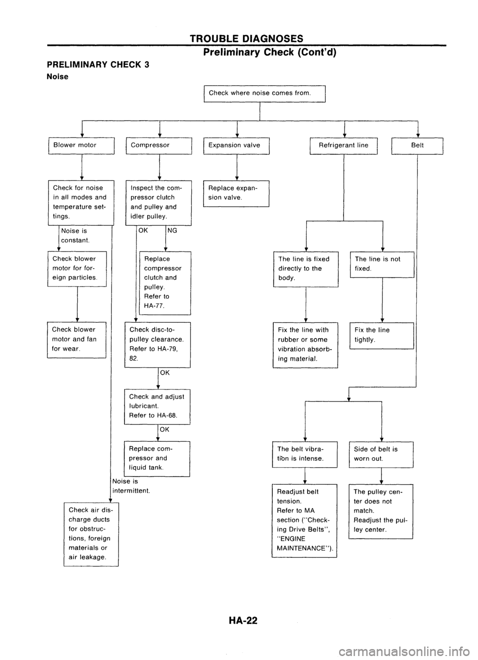
PRELIMINARY CHECK3
Noise TROUBLE
DIAGNOSES
Preliminary Check(Coni'd)
Check wherenoisecomes from.
I
I
Blower motor
Check fornoise
in all modes and
temperature set-
tings.
I
Compressor
Inspect thecom-
pressor clutch
and pulley and
idler pulley. Expansion
valve
Replace expan-
sion valve.
I
Refrigerant line
II
Belt
I
Noise is
constant.
OK
NG
Check blower
motor forfor-
eign particles.
Check blower
motor andfan
for wear. Replace
compressor
clutch and
pulley.
Refer to
HA-77.
Check disc-to-
pulley clearance.
Refer toHA-79,
82.
OK
Check andadjust
lubricant.
Refer toHA-68.
OK
Replace com-
pressor and
liquid tank. The
lineisfixed
directly tothe
body.
Fix the line with
rubber orsome
vibration absorb-
ing material.
The beltvibra-
tion isintense. The
lineisnot
fixed.
Fix the line
tightly.
Side ofbelt is
worn out.
Noise is
i nterm ittent.
Check airdis-
charge ducts
for obstruc-
tions, foreign
materials or
air leakage.
HA-22
Readjust
belt
tension.
Refer toMA
section ("Check-
ing Drive Belts",
"ENGINE
MAINTENANCE"). The
pulley cen-
ter does not
match.
Readjust thepul-
ley center.
Page 1425 of 1701
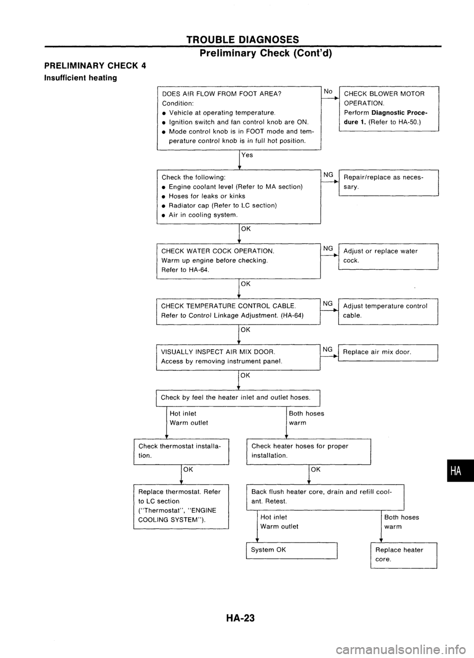
PRELIMINARY CHECK4
Insufficient heating TROUBLE
DIAGNOSES
Preliminary Check(Cont'd)
DOES AIRFLOW FROM FOOTAREA?
Condition:
• Vehicle atoperating temperature .
• Ignition switchandfancontrol knobareON.
• Mode control knobisin FOOT modeandtem-
perature controlknobisinfull hotposition.
Check thefollowing:
• Engine coolant level(Refer toMA section)
• Hoses forleaks orkinks
• Radiator cap(Refer toLC section)
• Air incooling system.
CHECK WATER COCKOPERATION.
Warm upengine before
checking.
Refer toHA-64.
OK
CHECK TEMPERATURE CONTROLCABLE.
Refer toControl Linkage Adjustment. (HA-64)
VISUALLY INSPECTAIRMIX DOOR.
Access byremoving instrument panel.
OK
Check byfeel theheater inletandoutlet hoses.
No
NG
NG
NG
NG
CHECK
BLOWER MOTOR
OPERATION.
Perform
Diagnostic Proce-
dure 1.
(Refer toHA-50.)
Repair/replace asneces-
sary .
Adjust orreplace water
cock.
Adjust temperature control
cable.
Replace airmix door.
Hot inlet
Warm outlet
Check thermostat installa-
tion.
OK
Both
hoses
warm
Check heater hosesforproper
installation.
OK
•
Back
flush heater core,drain andrefill cool-
ant. Retest.
Replace
thermostat. Refer
to LC section
("Thermostat", "ENGINE
COOLING SYSTEM"). Hot
inlet
Warm outlet
System OK
HA-23
Both
hoses
warm
Replace heater
core.
Page 1426 of 1701
TROUBLEDIAGNOSES
Performance TestDiagnoses
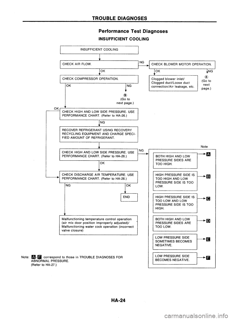
INSUFFICIENT COOLING
INSUFFICIENT COOLING
CHECK AIRFLOW.
OK CHECK
BLOWER MOTOROPERATION.
OK
CHECK COMPRESSOR OPERATION.
OK Clogged
blowerinlet!
Clogged duct/Loose duct
connection/Air leakage,etc.
@
(Go to
next
page.)
(Go to
next page.)
OK CHECK HIGHANDLOW SIDE PRESSURE. USE
PERFORMANCE CHART.(RefertoHA-26.)
NG
RECOVER REFRIGERANT USINGRECOVERY
RECYCLING EQUIPMENT ANDCHARGE SPECI-
FIED AMOUNT OFREFRIGERANT.
CHECK HIGHANDLOW SIDE PRESSURE. USE
PERFORMANCE CHART.(RefertoHA-26.)
OK
CHECK DISCHARGE AIRTEMPERATURE. USE
PERFORMANCE CHART.(RefertoHA-26.)
NG
Malfunctioning temperaturecontroloperation
(air mix door position improperly adjusted)/
Malfunctioning watercockoperation (incorrect
valve closure)
Note:
Fa-Ii
correspond tothose inTROUBLE DIAGNOSES FOR
ABNORMAL PRESSURE.
(Refer toHA-27.)
HA-24NG
Note
BOTH HIGHANDLOW
m
PRESSURE SIDESARE
TOO HIGH.
HIGH PRESSURE SIDEIS
(;]
TOO HIGH ANDLOW
PRESSURE SIDEISTOO
LOW.
HIGH PRESSURE SIDEIS
TOO LOW ANDLOW
PRESSURE SIDEISTOO
HIGH.
BOTH HIGHANDLOW
Ii]
PRESSURE SIDESARE
TOO LOW.
LOW PRESSURE SIDE
SOMETIMES BECOMES
NEGATIVE.
LOW PRESSURE SIDE
Ii
BECOMES NEGATIVE.
Page 1427 of 1701
TROUBLEDIAGNOSES
Performance TestDiagnoses (Cont'd)
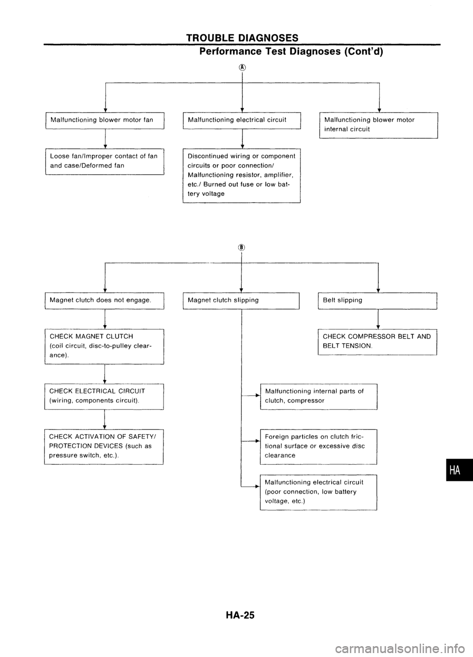
@
Malfunctioning blowermotorfan
Loose fan!lmproper contactoffan
and case!Deformed fan Malfunctioning
electricalcircuit
Discontinued wiringorcomponent
circuits orpoor connection!
Malfunctioning resistor,amplifier,
etc.! Burned outfuse orlow bat-
tery voltage Malfunctioning
blowermotor
internal circuit
Magnet clutchdoesnotengage.
CHECK MAGNET CLUTCH
(coil circuit, disc-to-pulley clear-
ance). Magnet
clutchslipping
Beltslipping
CHECK COMPRESSOR BELTAND
BELT TENSION.
CHECK ELECTRICAL CIRCUIT
(wiring, components circuit).
CHECK ACTIVATION OFSAFETY!
PROTECTION DEVICES(suchas
pressure switch,etc.). Malfunctioning
internalpartsof
clutch, compressor
Foreign particles onclutch fric-
tional surface orexcessive disc
clearance
Malfunctioning electricalcircuit
(poor connection, lowbattery
voltage, etc.)
HA-25
•
Page 1428 of 1701
TROUBLEDIAGNOSES
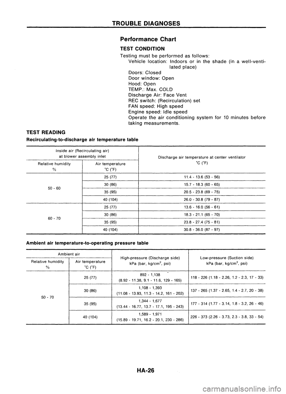
Performance Chart
TEST CONDITION
Testing mustbeperformed asfollows:
Vehicle location: Indoorsorinthe shade (inawell-venti-
lated place)
Doors: Closed
Door window: Open
Hood: Open
TEMP.: Max.COLD
Discharge Air:Face Vent
REC switch: (Recirculation) set
FAN speed: Highspeed
Engine speed:Idlespeed
Operate theairconditioning systemfor10minutes before
taking measurements.
TEST READING
Recirculating-to-discharge airtemperature table
Inside air(Recirculating air)
at blower assembly inlet
Dischargeairtemperature atcenter ventilator
Relative humidity
Airtemperature .C
('F)
%
.C
('F)
25 (77) 11.4
-13.6 (53-56)
30 (86) 15.7-18.3 (60-65)
50 -60
35(95) 20.5-23.8 (69-75)
40 (104) 26.0-30.8 (79-87)
25 (77) 13.6-16.0 (56-61)
30 (86) 18.3-21.1 (65-70)
60 -70
35(95) 23.8-27.4 (75-81)
40 (104) 30.8-36.0 (87-97)
Ambient airtemperature-to-operating pressuretable
Ambient air
High-pressure(Dischargeside) Low-pressure
(Suctionside)
Relative humidity Airtemperature
kPa(bar,
kg/cm
2,
psi) kPa
(bar,
kg/cm
2,
psi)
%
.C
('F)
.
25 (77) 892
-1,138
118-226 (1.18 -2.26,1.2 -2.3,17 -33)
(8.92 -11.38, 9.1-11.6,129 -165)
30 (86) 1,108
-1,393
137-265 (1.37 -2.65,1.4 -2.7,20 -38)
(11.08 -13.93, 11.3-14.2, 161-202)
50 -70
35(95) 1,344
-1,677
177-314 (1.77 -3.14,1.8 -3.2, 26-46)
(1344 -16.77,13.7 -17.1, 195-243)
40 (104) 1,589
-1,971
226-373 (2.26 -3.73, 2.3-3.8, 33-54)
(15.89 -19.71,16.2 -20.1, 230-286)
HA-26
Page 1429 of 1701
TROUBLEDIAGNOSES
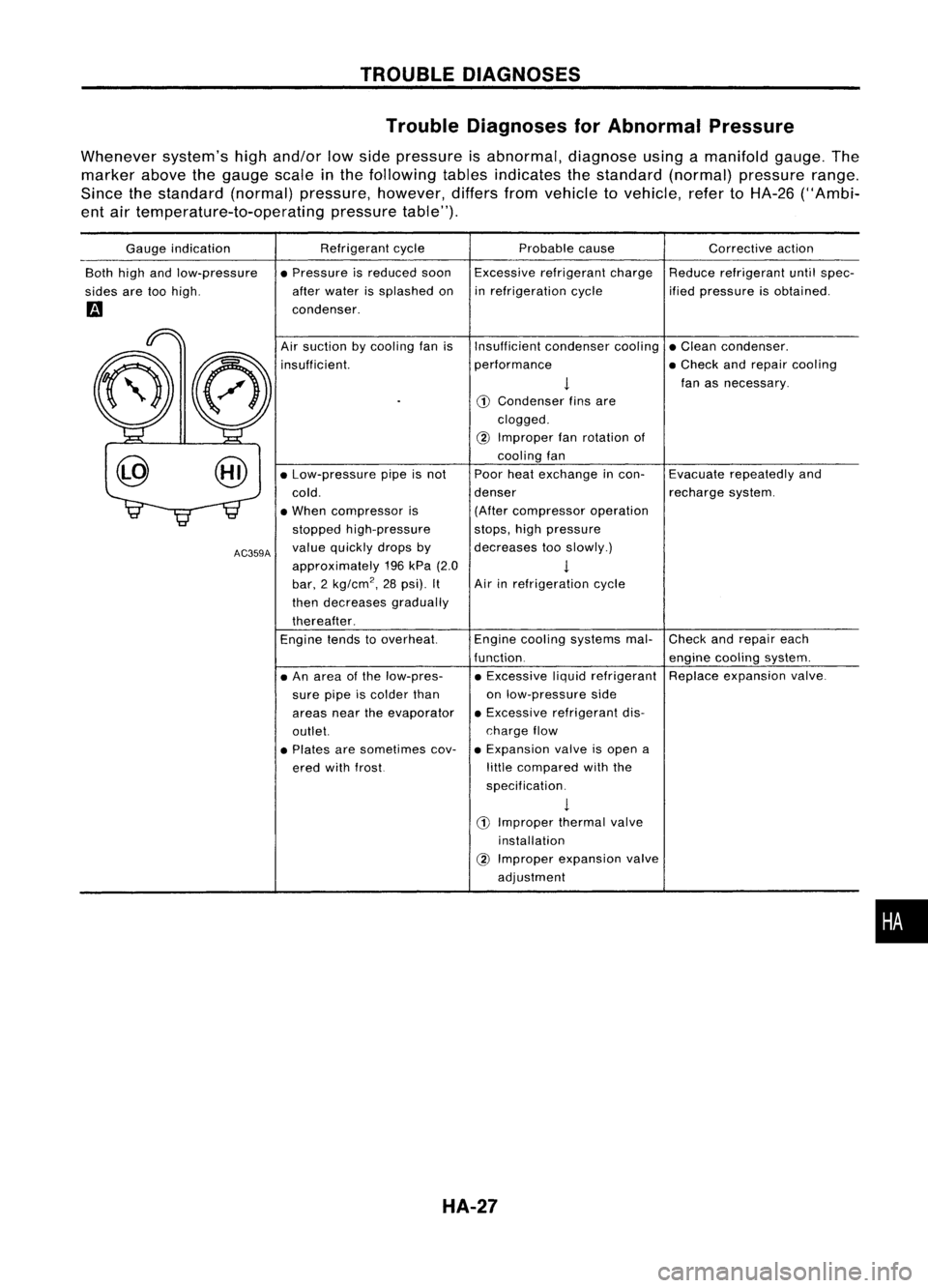
Trouble Diagnoses forAbnormal Pressure
Whenever system'shighand/or lowside pressure isabnormal, diagnoseusingamanifold gauge.The
marker abovethegauge scale
in
the following tablesindicates thestandard (normal)pressure range.
Since thestandard (normal)pressure, however,differsfromvehicle tovehicle, refertoHA-26 ("Ambi-
ent airtemperature-to-operating pressuretable").
Gauge indication
Both highandlow-pressure
sides aretoohigh.
m
Refrigerant
cycle
• Pressure isreduced soon
after water issplashed on
condenser. Probable
cause
Excessive refrigerant charge
in refrigeration cycle Corrective
action
Reduce refrigerant untilspec-
ified pressure isobtained.
•
Check
andrepair each
engine cooling system.
Replace expansion valve.
Evacuate
repeatedly and
recharge system.
Insufficient
condensercooling•Clean condenser.
performance •Check andrepair cooling
!
fanasnecessary.
CD
Condenser finsare
clogged.
@
Improper fanrotation of
cooling fan
Poor heatexchange incon-
denser (After compressor operation
stops, highpressure
decreases tooslowly.)
1
Air inrefrigeration cycle
Engine cooling systems mal-
function. • Excessive liquidrefrigerant
on low-pressure side
• Excessive refrigerant dis-
charge flow
• Expansion valveisopen a
little compared withthe
specification.
1
CD
Improper thermalvalve
installation
@
Improper expansion valve
adjustment
Air
suction bycooling fanis
insufficient.
• An area ofthe low-pres-
sure pipeiscolder than
areas neartheevaporator
outlet.
• Plates aresometimes cov-
ered withfrost.
•
Low-pressure pipeisnot
cold.
• When compressor is
stopped high-pressure
value quickly dropsby
approximately 196kPa (2.0
bar, 2
kg/cm
2,
28psi). It
then decreases gradually
thereafter.
Engine tendstooverheat.
AC359A
HA-27
Page 1430 of 1701
TROUBLEDIAGNOSES
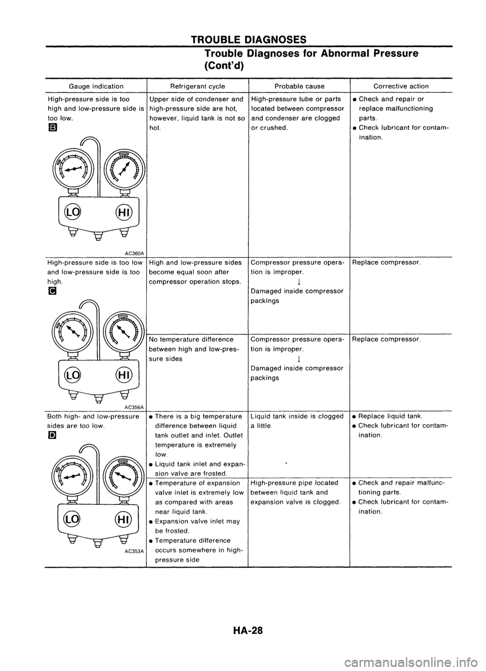
Trouble Diagnoses forAbnormal Pressure
(Cont'd)
Compressorpressureopera-Replacecompressor.
tion isimproper.
1
Damaged insidecompressor
packings
Gauge
indication
High-pressure sideistoo
high andlow-pressure sideis
too low.
AC360A
High-pressure sideistoo low
and low-pressure sideistoo
high.
[;J
AC356A
80th high- andlow-pressure
sides aretoolow.
I!]
AC353A
Refrigerant
cycle
Upper sideofcondenser and
high-pressure sidearehot,
however, liquidtankisnot so
hot.
High andlow-pressure sides
become equalsoonafter
compressor operationstops.
No temperature difference
between highandlow-pres-
sure sides
• There isabig temperature
difference betweenliquid
tank outlet andinlel. Outlet
temperature isextremely
low .
• Liquid tankinletandexpan-
sion valve arefrosted.
• Temperature ofexpansion
valve inletisextremely low
as compared withareas
near liquid tank.
• Expansion valveinletmay
be frosted .
• Temperature difference
occurs somewhere inhigh-
pressure side Probable
cause
High-pressure tubeorparts
located between compressor
and condenser areclogged
or crushed.
Compressor pressureopera-
tion isimproper.
1
Damaged insidecompressor
packings
Liquid tankinside isclogged
a lillie.
High-pressure pipelocated
between liquidtankand
expansion valveisclogged. Corrective
action
• Check andrepair or
replace malfunctioning
parts .
• Check lubricant forcontam-
ination.
Replace compressor.
• Replace liquidtank.
• Check lubricant forcontam-
ination.
• Check andrepair malfunc-
tioning parts.
• Check lubricant forcontam-
ination.
HA-28