NISSAN ALMERA N15 1995 Service Manual
Manufacturer: NISSAN, Model Year: 1995, Model line: ALMERA N15, Model: NISSAN ALMERA N15 1995Pages: 1701, PDF Size: 82.27 MB
Page 1371 of 1701
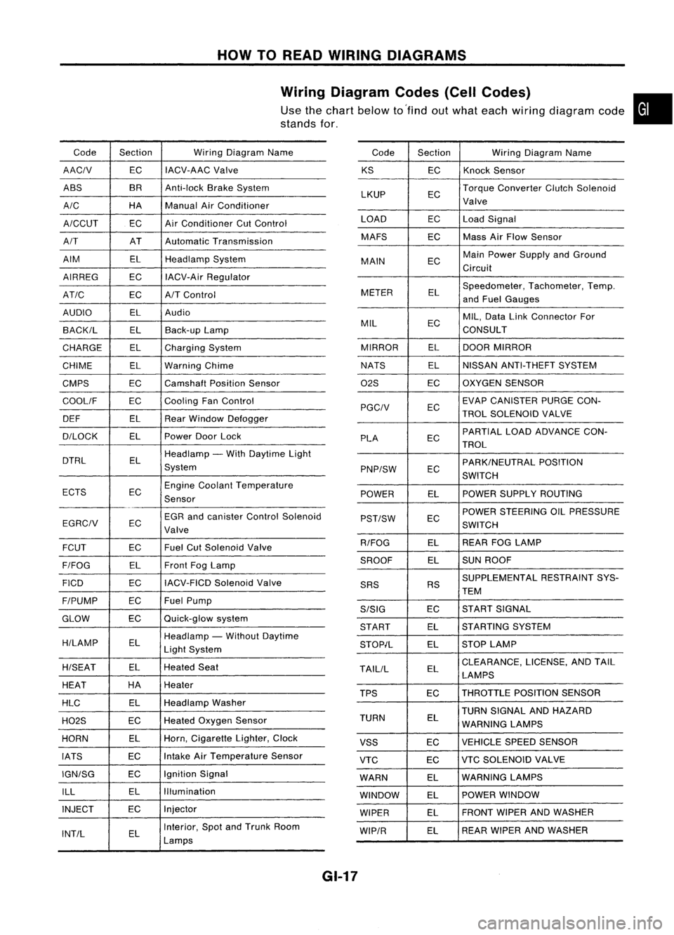
HOWTOREAD WIRING DIAGRAMS
Wiring Diagram Codes(CellCodes)
Use thechart below to'find outwhat each wiring diagram code•
stands for,
Code Section WiringDiagram Name
AACIV ECIACV-AAC
Valve
ABS BR
Anti-lock BrakeSystem
A/C HAManualAirConditioner
A/CCUT ECAir
Conditioner CutControl
A/T ATAutomatic Transmission
AIM ELHeadlamp System
AIRREG ECIACV-Air Regulator
AT/C ECA/TControl
AUDIO ELAudio
BACK/L ELBack-up Lamp
CHARGE ELCharging System
CHIME ELWarning Chime
CMPS EC
Camshaft PositionSensor
COOllF ECCooling
FanControl
DEF ELRearWindow Defogger
D/LOCK ELPowerDoorLock
DTRL ELHeadlamp
-With Daytime Light
System
ECTS ECEngine
Coolant Temperature
Sensor
EGR andcanister ControlSolenoid
EGRCIV EC
Valve
FCUT ECFuel
CutSolenoid Valve
F/FOG ELFront
FogLamp
FICO ECIACV-FICD
SolenoidValve
F/PUMP ECFuel
Pump
GLOW ECQuick-glow
system
H/LAMP ELHeadlamp
-Without Daytime
Light System
H/SEAT ELHeated
Seat
HEAT HA
Heater
HLC ELHeadlamp
Washer
H02S ECHeated
Oxygen Sensor
HORN ELHorn,
Cigarette Lighter,Clock
IATS ECIntake
AirTemperature Sensor
IGN/SG ECIgnition
Signal
ILL ELIllumination
INJECT ECInjector
INT/L ELInterior,
SpotandTrunk Room
Lamps Code
Section WiringDiagram Name
KS ECKnock
Sensor
LKUP ECTorque
Converter ClutchSolenoid
Valve
LOAD ECLoadSignal
MAFS ECMass
AirFlow Sensor
MAIN ECMain
Power Supply andGround
Circuit
METER ELSpeedometer,
Tachometer,Temp.
and Fuel Gauges
MIL ECMIL,
Data LinkConnector For
CONSULT
MIRROR ELDOOR
MIRROR
NATS ELNISSAN
ANTI-THEFT SYSTEM
02S ECOXYGEN
SENSOR
EC EVAP
CANISTER PURGECON-
PGCIV TROLSOLENOID VALVE
PLA ECPARTIAL
LOADADVANCE CON-
TROL
EC PARK/NEUTRAL
POSITION
PNP/SW SWITCH
POWER ELPOWER
SUPPLY ROUTING
POWER STEERING OILPRESSURE
PST/SW EC
SWITCH
R/FOG ELREAR
FOGLAMP
SROOF ELSUN
ROOF
SUPPLEMENTAL RESTRAINTSYS-
SRS RS
TEM
S/SIG ECST
ART SIGNAL
START ELSTARTING
SYSTEM
STOP/L ELSTOP
LAMP
TAllIL ELCLEARANCE,
LICENSE,ANDTAIL
LAMPS
TPS ECTHROTTLE
POSITIONSENSOR
TURN SIGNAL ANDHAZARD
TURN EL
WARNING LAMPS
VSS ECVEHICLE
SPEEDSENSOR
VTC ECVTC
SOLENOID VALVE
WARN ELWARNING
LAMPS
WINDOW ELPOWER
WINDOW
WIPER ELFRONT
WIPERANDWASHER
WIP/R ELREAR
WIPER ANDWASHER
GI-17
Page 1372 of 1701
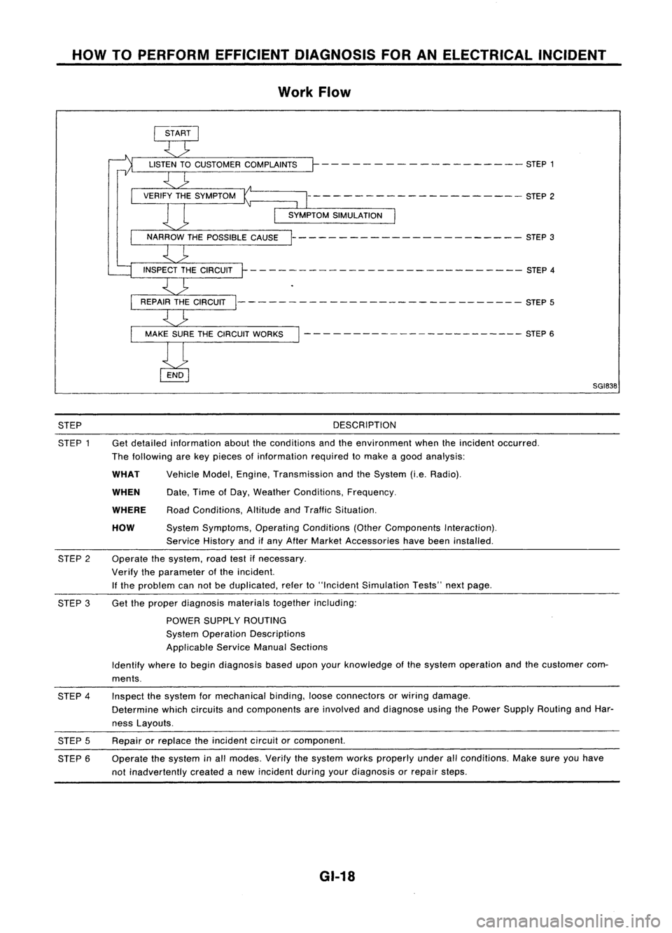
HOWTOPERFORM EFFICIENT DIAGNOSIS FORANELECTRICAL INCIDENT
Work Flow
- - - -- - -- ------ -- - -- STEP 1
--------------------- STEP2
----------------------- STEP3
- - -- ---- - --- - -- --- --- - - --- -- STEP 4
--------- -------------------- STEP5
- - - - ---- -- -- -- -- -- --- --- STEP 6
SGI838
STEP
STEP 1 DESCRIPTION
Get detailed information abouttheconditions andtheenvironment whentheincident occurred.
The following arekey pieces ofinformation requiredtomake agood analysis:
HOW
WHEN
WHAT
WHERE
Vehicle
Model,Engine, Transmission andtheSystem (i.e.Radio).
Date, TimeofDay, Weather Conditions, Frequency.
Road Conditions, AltitudeandTraffic Situation.
System Symptoms, OperatingConditions (OtherComponents Interaction).
Service Historyandifany After Market Accessories havebeen installed.
Operate thesystem, roadtestifnecessary.
Verify theparameter ofthe incident.
If the problem cannotbeduplicated, referto"Incident Simulation Tests"nextpage.
STEP
2
STEP 3Get
theproper diagnosis materialstogetherincluding:
POWER SUPPLY ROUTING
System Operation Descriptions
Applicable ServiceManualSections
Identify wheretobegin diagnosis baseduponyourknowledge ofthe system operation andthecustomer com-
ments.
STEP 4
STEP 5
STEP 6 Inspect
thesystem formechanical binding,looseconnectors orwiring damage.
Determine whichcircuits andcomponents areinvolved anddiagnose usingthePower Supply Routing andHar-
ness Layouts.
Repair orreplace theincident circuitorcomponent.
Operate thesystem inall modes. Verifythesystem worksproperly underallconditions. Makesureyouhave
not inadvertently createdanew incident duringyourdiagnosis orrepair steps.
GI-18
Page 1373 of 1701
HOWTOPERFORM EFFICIENT DIAGNOSIS FORANELECTRICAL INCIDENT
Incident Simulation Tests
INTRODUCTION
Sometimes thesymptom isnot present whenthevehicle isbrought infor service.
If
possible, re-create
the conditions presentatthe time ofthe incident. Doingsomay help avoid aNo Trouble FoundDiag-
nosis. Thefollowing sectionillustrates waystosimulate theconditionslenvironment underwhich the
owner experiences anelectrical incident.
The section isbroken intothesixfollowing topics:
• Vehicle vibration
• Heat sensitive
• Freezing
• Water intrusion
• Electrical load
• Cold orhot start up
Get athorough description ofthe incident fromthecustomer. Itis important forsimulating thecondi-
tions ofthe problem.
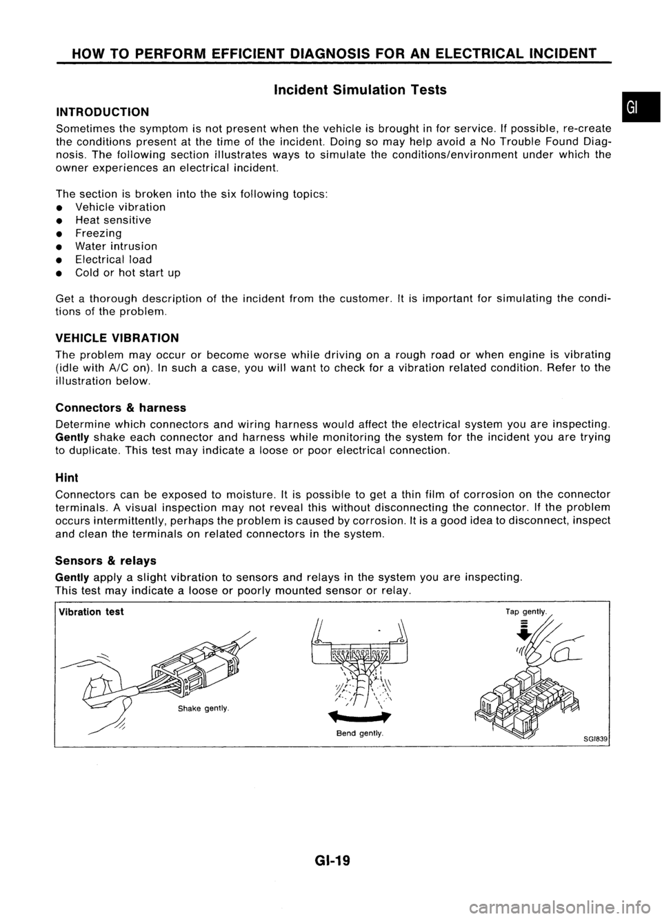
VEHICLE VIBRATION
The problem mayoccur orbecome worsewhiledriving onarough roadorwhen engine isvibrating
(idle with
AIC
on). Insuch acase, youwillwant tocheck foravibration relatedcondition. Refertothe
illustration below.
Connectors
&
harness
Determine whichconnectors andwiring harness wouldaffecttheelectrical systemyouareinspecting.
Gently
shakeeachconnector andharness whilemonitoring thesystem forthe incident youaretrying
to duplicate. Thistestmay indicate aloose orpoor electrical connection.
Hint
Connectors canbeexposed tomoisture. Itis possible toget athin film ofcorrosion onthe connector
terminals. Avisual inspection maynotreveal thiswithout disconnecting theconnector. Ifthe problem
occurs intermittently, perhapstheproblem iscaused bycorrosion. Itis agood ideatodisconnect, inspect
and clean theterminals onrelated connectors inthe system.
Sensors
&
relays
Gently
applyaslight vibration tosensors andrelays inthe system youareinspecting.
This testmay indicate aloose orpoorly mounted sensororrelay.
•
Vibration test
Bendgently.
GI-19
Tap
gently.
8GI839
Page 1374 of 1701
HOWTOPERFORM EFFICIENT DIAGNOSIS FORANELECTRICAL INCIDENT
Incident Simulation Tests(Cont'd)
Wirestrands
missing
Intermittent
signals
through
pierced
insulation
Proper crimp Insulation not
removed
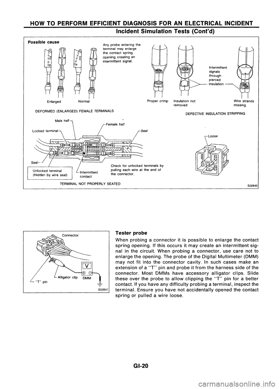
Any
probe entering the
terminal mayenlarge
the contact spring
opening creatingan
intermittent signal.
Normal
II
Po
1/
I~
I,
::0
II
\':!J
Enlarged
Possible
cause
DEFORMED (ENLARGED) FEMALETERMINALS
DEFECTIVEINSULATION STRIPPING
Seal
Intermittent
contact Female
half
Check forunlocked terminals by
pulling eachwireatthe end of
the connector.
/
[1/
TERMINAL NOTPROPERLY SEATED
SGI840
SGI841 Tester
probe
When probing aconnector itis possible toenlarge thecontact
spring opening. Ifthis occurs itmay create anintermittent sig-
nal inthe circuit. Whenprobing aconnector, usecare notto
enlarge theopening. Theprobe ofthe Digital Multimeter (DMM)
may notfitinto theconnector cavity.
In
such cases makean
extension ofa"T" pinand probe itfrom theharness sideofthe
connector. MostDMMs haveaccessory alligatorclips.Slide
these overtheprobe toallow clipping the"T" pinforabetter
contact. Ifyou have anydifficulty probingaterminal, inspectthe
terminal. Ensureyouhave notaccidentally openedthecontact
spring orpulled awire loose.
GI-20
Page 1375 of 1701
HOWTOPERFORM EFFICIENT DIAGNOSIS FORANELECTRICAL INCIDENT
Incident Simulation Tests(Cont'd)
Engine compartment
There areseveral reasons avehicle orengine vibration could•
cause anelectrical complaint. Someofthe things tocheck for
are:
• Connectors notfully seated.
• Wiring harness notlong enough andisbeing stressed due
to engine vibrations orrocking.
• Wires laying across brackets ormoving components.
• Loose, dirtyorcorroded groundwires.
• Wires routed tooclose tohot components.
To inspect components underthehood, startbyverifying the
integrity ofground connections. (RefertoGROUND INSPEC-
TION described later.)Firstcheck thatthesystem isproperly
grounded. Thencheck forloose connection by
gently shaking
the wiring orcomponents aspreviously explained. Usingthe
wiring diagrams inspectthewiring forcontinuity.
Behind theinstrument panel
An improperly routedorimproperly clampedharnesscan
become pinchedduringaccessory installation. Vehiclevibra-
tion canaggravate aharness whichisrouted alongabracket
or near ascrew.
Under seating areas
An unclamped orloose harness cancause wiring tobe pinched
by seat components (suchasslide guides) duringvehicle vibra-
tion. Ifthe wiring runsunder seating areas,inspect wirerout-
ing forpossible damageorpinching.
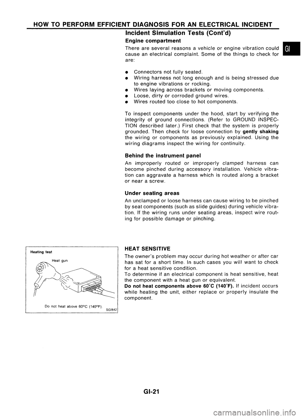
Heating test
Do not heat above 60°C(140°F).
8GI842 HEAT
SENSITIVE
The owner's problem mayoccur during hotweather orafter car
has satforashort time.Insuch cases youwillwant tocheck
for aheat sensitive condition.
To determine ifan electrical component isheat sensitive, heat
the component withaheat gunorequivalent.
Do not heat components above
60°C
(140°F).
Ifincident occurs
while heating theunit, either replace orproperly insulatethe
component.
GI-21
Page 1376 of 1701
HOWTOPERFORM EFFICIENT DIAGNOSIS FORANELECTRICAL INCIDENT
Incident Simulation Tests(Cont'd)
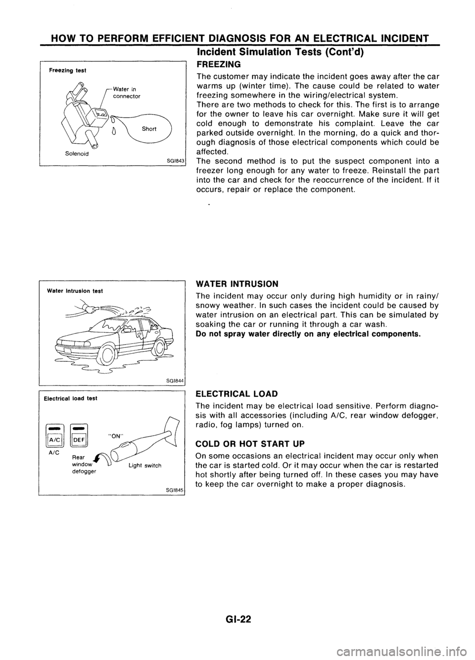
FREEZING
Freezing test
Solenoid
Water
in
connector
The
customer mayindicate theincident goesaway afterthecar
warms up(winter time).Thecause couldberelated towater
freezing somewhere inthe wiring/electrical system.
There aretwo methods tocheck forthis. Thefirst isto arrange
for the owner toleave hiscar overnight. Makesureitwill get
cold enough todemonstrate hiscomplaint. Leavethecar
parked outside overnight. Inthe morning, doaquick andthor-
ough diagnosis ofthose electrical components whichcouldbe
affected.
SGI843
Thesecond method isto put the suspect component intoa
freezer longenough forany water tofreeze. Reinstall thepart
into thecar and check forthe reoccurrence ofthe incident. Ifit
occurs, repairorreplace thecomponent.
Water Intrusion test
WATER
INTRUSION
The incident mayoccur onlyduring highhumidity orinrainy/
snowy weather. Insuch cases theincident couldbecaused by
water intrusion onan electrical part.Thiscanbesimulated by
soaking thecar orrunning itthrough acar wash.
Do not spray waterdirectly onany electrical components.
SGI844
Electrical loadtest
AIC SGI845ELECTRICAL
LOAD
The incident maybeelectrical loadsensitive. Performdiagno-
sis with allaccessories (includingA/C,rearwindow defogger,
radio, foglamps) turnedon.
COLD ORHOT START UP
On some occasions anelectrical incidentmayoccur onlywhen
the car isstarted cold.Oritmay occur whenthecar isrestarted
hot shortly afterbeing turned off.Inthese cases youmay have
to keep thecar overnight tomake aproper diagnosis.
GI-22
Page 1377 of 1701
•SHORT CIRCUIT
• SHORT TOGROUND
HOW
TOPERFORM EFFICIENT DIAGNOSIS FORANELECTRICAL INCIDENT
Circuit Inspection
•
A circuit isopen when thereisno continuity throughasection ofthe circuit.
There aretwo types ofshorts.
Whenacircuit contacts anothercircuitandcauses the
normal resistance tochange.
When acircuit contacts aground sourceandgrounds the
circuit.
INTRODUCTION
In general, testingelectrical circuitsisan easy taskifitis approached inalogical andorganized method.
Before beginning itis important tohave allavailable information onthe system tobe tested. Also,get
a thorough understanding ofsystem operation. Thenyouwillbeable touse theappropriate equipment
and follow thecorrect testprocedure.
You may have tosimulate vehiclevibrations whiletesting electrical components.
Gentlyshake
thewir-
ing harness orelectrical component todo this.
OPEN
SHORT
TESTING FOR"OPENS" INTHE CIRCUIT
[YJ
(Voltage check)
Before
youbegin todiagnose andtestthesystem, youshould roughsketch aschematic ofthe system.
This willhelp youtologically walkthrough thediagnosis process.Drawingthesketch willalso reinforce
your working knowledge ofthe system.
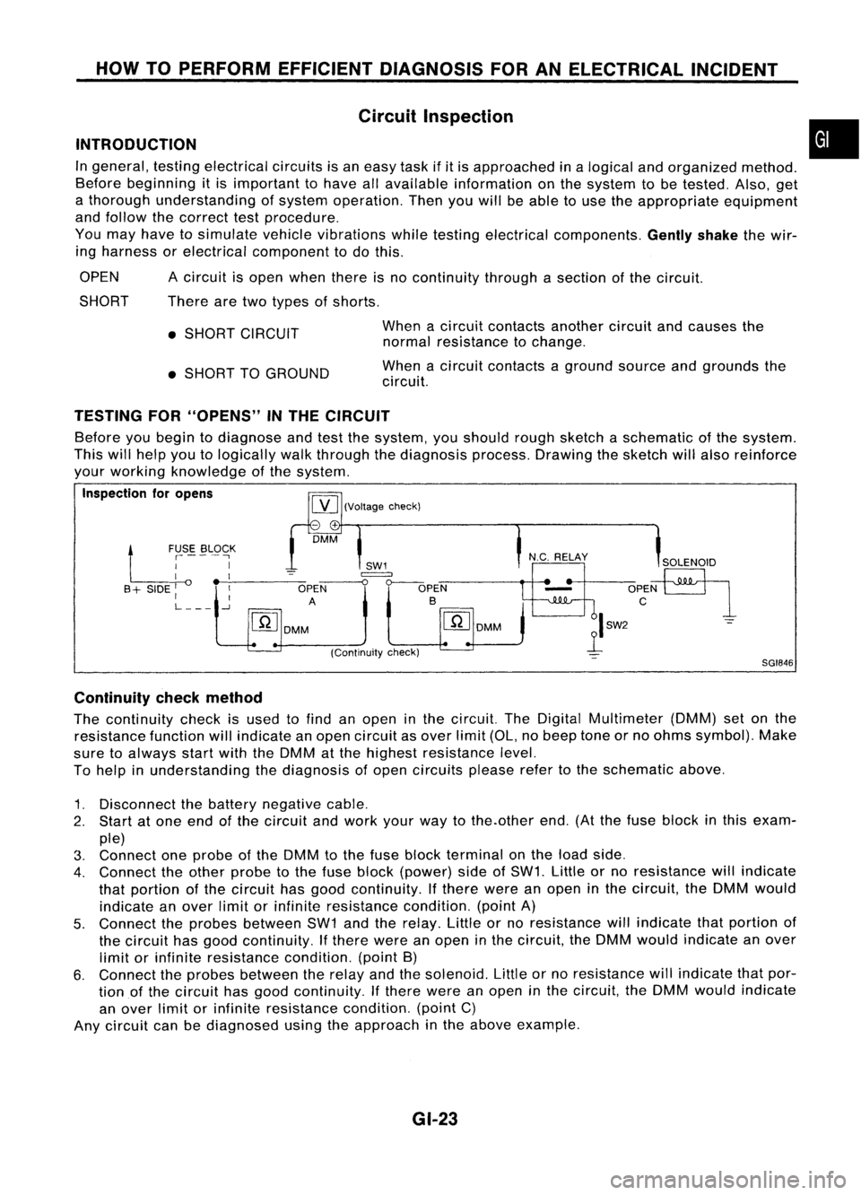
Inspection foropens
-+
DMM
Ll
~SE. ~L9~K
I
I
I __-,----
B + SIDE
I
OPEN
I I
A
L
-.J
[ill
DMM
SGI846
Continuity checkmethod
The continuity checkisused tofind anopen inthe circuit. TheDigital Multimeter (DMM)setonthe
resistance functionwillindicate anopen circuit asover limit(OL,nobeep toneorno ohms symbol). Make
sure toalways startwiththeDMM atthe highest resistance level.
To help inunderstanding thediagnosis ofopen circuits pleaserefertothe schematic above.
1. Disconnect thebattery negative cable.
2. Start atone end ofthe circuit andwork yourwaytothe.other end.(Atthe fuse block inthis exam-
ple)
3. Connect oneprobe ofthe DMM tothe fuse block terminal onthe load side.
4. Connect theother probe tothe fuse block (power) sideofSW1. Littleorno resistance willindicate
that portion ofthe circuit hasgood continuity. Ifthere wereanopen inthe circuit, theDMM would
indicate anover limitorinfinite resistance condition.(pointA)
5. Connect theprobes between SW1andtherelay. Littleorno resistance willindicate thatportion of
the circuit hasgood continuity. Ifthere wereanopen inthe circuit, theDMM would indicate anover
limit orinfinite resistance condition.(pointB)
6. Connect theprobes between therelay andthesolenoid. Littleorno resistance willindicate thatpor-
tion ofthe circuit hasgood continuity. Ifthere wereanopen inthe circuit, theDMM would indicate
an over limitorinfinite resistance condition.(pointC)
Any circuit canbediagnosed usingtheapproach inthe above example.
GI-23
Page 1378 of 1701
HOWTOPERFORM EFFICIENT DIAGNOSIS FORANELECTRICAL INCIDENT
Circuit Inspection (Cont'd)
Voltage checkmethod
To help inunderstanding thediagnosis ofopen circuits pleaserefertothe previous schematic.
In any powered circuit,anopen canbefound bymethodically checkingthesystem forthe presence of
voltage. Thisisdone byswitching theDMM tothe voltage function.
1. Connect oneprobe ofthe DMM toaknown goodground.
2. Begin probing atone endofthe circuit andwork yourwaytothe other end.
3. With SW1open, probe atSW1 tocheck forvoltage.
voltage; openisfurther downthecircuit thanSW1.
no voltage; openisbetween fuseblock andSW1 (point A).
4. Close SW1andprobe atrelay.
voltage; openisfurther downthecircuit thantherelay.
no voltage; openisbetween SW1andrelay (point B).
5. Close therelay andprobe atthe solenoid.
voltage; openisfurther downthecircuit thanthesolenoid.
no voltage; openisbetween relayandsolenoid (pointC).
Any powered circuitcanbediagnosed usingtheapproach inthe above example.
SGI847
RELAY
~I SH~
SW2
c
1
(Resistance
check)
IGN "ON"
t
OR "S~:R.T~ '::~SEBLOCK
I I '-
SWl
I I
-=
B+SIOEl~~-:-~
~r-o~
SHORT SHORT
[YJ
DMMA B
+ -
(Voltage check)
TESTING
FOR"SHORTS" INTHE CIRCUIT
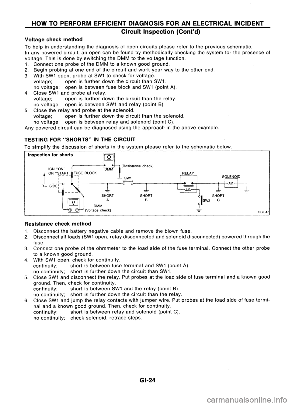
To simplify thediscussion ofshorts inthe system pleaserefertothe schematic below.
Inspection forshorts
Resistance checkmethod
1. Disconnect thebattery negative cableandremove theblown fuse.
2. Disconnect allloads (SW1open, relaydisconnected andsolenoid disconnected) poweredthroughthe
fuse.
3. Connect oneprobe ofthe ohmmeter tothe load sideofthe fuse terminal. Connecttheother probe
to aknown goodground.
4. With SW1open, check forcontinuity.
continuity; shortisbetween fuseterminal andSW1 (point A).
no continuity; shortisfurther downthecircuit thanSW1.
5. Close SW1anddisconnect therelay. Putprobes atthe load side offuse terminal andaknown good
ground. Then,check forcontinuity.
continuity; shortisbetween SW1andtherelay (point B),
no continuity; shortisfurther downthecircuit thantherelay.
6. Close SW1andjump therelay contacts withjumper wire.Putprobes atthe load sideoffuse termi-
nal and aknown goodground. Then,check forcontinuity.
continuity; shortisbetween relayandsolenoid (pointC).
no continuity; checksolenoid, retracesteps.
GI-24
Page 1379 of 1701
HOWTOPERFORM EFFICIENT DIAGNOSIS FORANELECTRICAL INCIDENT
Circuit Inspection (Cont'd)
Voltage checkmethod
1. Remove theblown fuseanddisconnect allloads (i.e.SW1 open, relaydisconnected andsolenoid •
disconnected) poweredthroughthefuse.
2. Turn theignition keytothe ONorSTART position. Verifybattery voltage atthe B
+
side ofthe fuse
terminal (oneleadonthe B
+
terminal sideofthe fuse block andone lead onaknown goodground).
3. With SW1 open andtheDMM leads across bothfuseterminals, checkforvoltage.
voltage; shortisbetween fuseblock andSW1 (point A).
no voltage; shortisfurther downthecircuit thanSW1.
4. With SW1 closed, relayandsolenoid disconnected andtheDMM leadsacross bothfuseterminals,
check forvoltage.
voltage; shortisbetween SW1andtherelay (point B).
no voltage; shortisfurther downthecircuit thantherelay.
5. With SW1 closed, relaycontacts jumpedwithfused jumper wirecheck forvoltage.
voltage; shortisdown thecircuit ofthe relay orbetween therelay andthedisconnected sole-
noid (point C).
no voltage; retracestepsandcheck power tofuse block.
GROUND INSPECTION
Ground connections arevery important tothe proper operation ofelectrical andelectronic circuits.
Ground connections areoften exposed tomoisture, dirtand other corrosive elements. Thecorrosion
(rust) canbecome anunwanted resistance. Thisunwanted resistance canchange theway acircuit
works. Electronically controlledcircuitsarevery sensitive toproper grounding. Aloose orcorroded groundcan
drastically affectanelectronically controlledcircuit.Apoor orcorroded groundcaneasily affectthecir-
cuit. Even when theground connection looksclean, therecanbeathin film ofrust onthe surface.
When inspecting aground connection followtheserules:
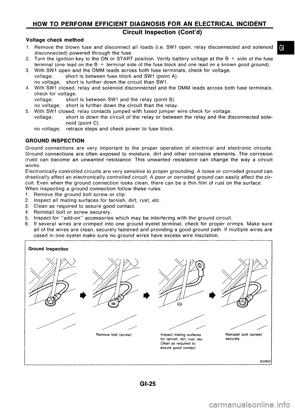
1. Remove theground boltscrew orclip.
2. Inspect allmating surfaces fortarnish, dirt,rust, etc.
3. Clean asrequired toassure goodcontact.
4. Reinstall boltorscrew securely.
5. Inspect for"add-on" accessories whichmaybeinterfering withtheground circuit.
6. Ifseveral wiresarecrimped intoone ground eyeletterminal, checkforproper crimps. Makesure
all ofthe wires areclean, securely fastened andproviding agood ground path.Ifmultiple wiresare
cased inone eyelet makesurenoground wireshaveexcess wireinsulation.
Ground Inspection
•
Removeboll(screw).
•
GI-25
Inspect
matingsurfaces
for tarnish. dirt.rust. etc.
Clean asrequired to
assure goodcontact.
•
Reinstallbolt(screw)
securely.
SGI853
Page 1380 of 1701
HOWTOPERFORM EFFICIENT DIAGNOSIS FORANELECTRICAL INCIDENT
Circuit Inspection (Cont'd)
VOLTAGE DROPTESTS
Voltage droptests areoften usedtofind components orcircuits whichhaveexcessive resistance. A
voltage dropinacircuit iscaused byaresistance
whenthecircuit isin operation.
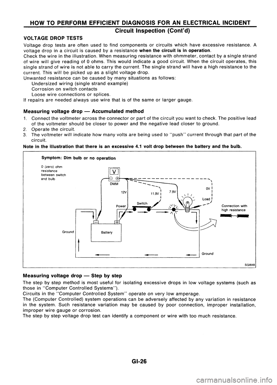
Check thewire inthe illustration. Whenmeasuring resistancewithohmmeter, contactbyasingle strand
of wire willgive reading of0ohms. Thiswould indicate agood circuit. Whenthecircuit operates, this
single strand ofwire isnot able tocarry thecurrent. Thesingle strand willhave ahigh resistance tothe
current. Thiswillbepicked upasaslight voltage drop.
Unwanted resistance canbecaused bymany situations asfollows:
Undersized wiring(single strandexample)
Corrosion onswitch contacts
Loose wireconnections orsplices.
If
repairs areneeded alwaysusewire thatisof the same orlarger gauge.
Measuring voltagedrop-Accumulated method
1. Connect thevoltmeter acrosstheconnector orpart ofthe circuit youwant tocheck. Thepositive lead
of the voltmeter shouldbecloser topower andthenegative leadcloser toground.
2. Operate thecircuit.
3. The voltmeter willindicate howmany voltsarebeing usedto"push" current through thatpart ofthe
circuit.
Note inthe illustration thatthere isan excessive 4.1volt drop between thebattery andthebulb.
Symptom: Dimbulb orno operation
Switch Connectionwith
high resistance
l ;
--
------------------~
--
\
~~~~ I
-, OVI
11.9V:
'I
I
Load)
--
12V
DMM
Battery
Ground
o
(zero) ohm
resistance
between switch
and bulb
t
•
__
Ground
SGI848
Measuring voltagedrop-Step bystep
The step bystep method ismost useful forisolating excessive dropsinlow voltage systems (suchas
those in"Computer ControlledSystems").
Circuits inthe "Computer ControlledSystem"operateonvery lowamperage.
The (Computer Controlled) systemoperations canbeadversely affectedbyany variation inresistance
in the system. Suchresistance variationmaybecaused bypoor connection, improperinstallation,
improper wiregauge orcorrosion.
The step bystep voltage droptestcan identify acomponent orwire withtoomuch resistance.
GI-26