NISSAN ALMERA N15 1995 Service Manual
Manufacturer: NISSAN, Model Year: 1995, Model line: ALMERA N15, Model: NISSAN ALMERA N15 1995Pages: 1701, PDF Size: 82.27 MB
Page 1391 of 1701
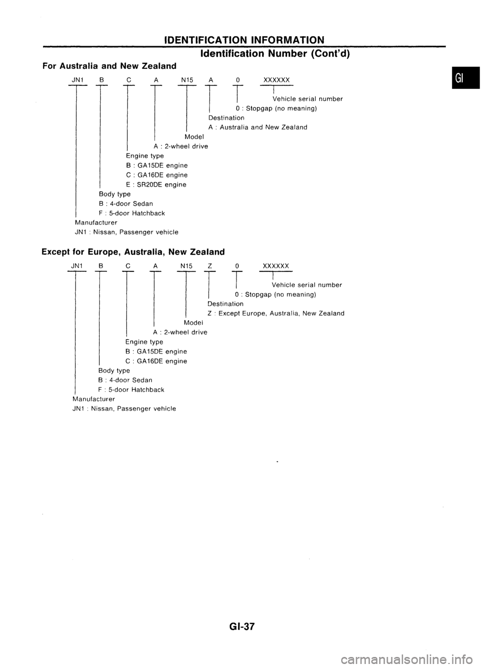
ForAustralia andNew Zealand IDENTIFICATION
INFORMATION
Identification Number(Cont'd)
JN1 B
c
A
N15A 0
xxxxxx
T
T
T
~ehicleserialnumber
o :
Stopgap (nomeaning)
Destination
A :Australia andNew Zealand
•
Model
A :2-wheel drive
Engine type
B :GA15DE engine
C: GA16DE engine
E :SR20DE engine
Body type
B :4-door Sedan
F :5-door Hatchback
Manufacturer
JN1 :Nissan, Passenger vehicle
Except forEurope, Australia, NewZealand
JN1 BC AN15Z 0
xxxxxx
T
T
T
~ehicleserialnumber
o :
Stopgap (nomeaning)
Destination
Z .Except Europe, Australia, NewZealand
Model
A :2-wheel drive
Engine type
B :GA 15DE engine
C :GA16DE engine
Body type
B :4-door Sedan
F :5-door Hatchback
Manufacturer
JN1 :Nissan, Passenger vehicle
GI.37
Page 1392 of 1701
IDENTIFICATIONINFORMATION
Identification Number(Cont'd)
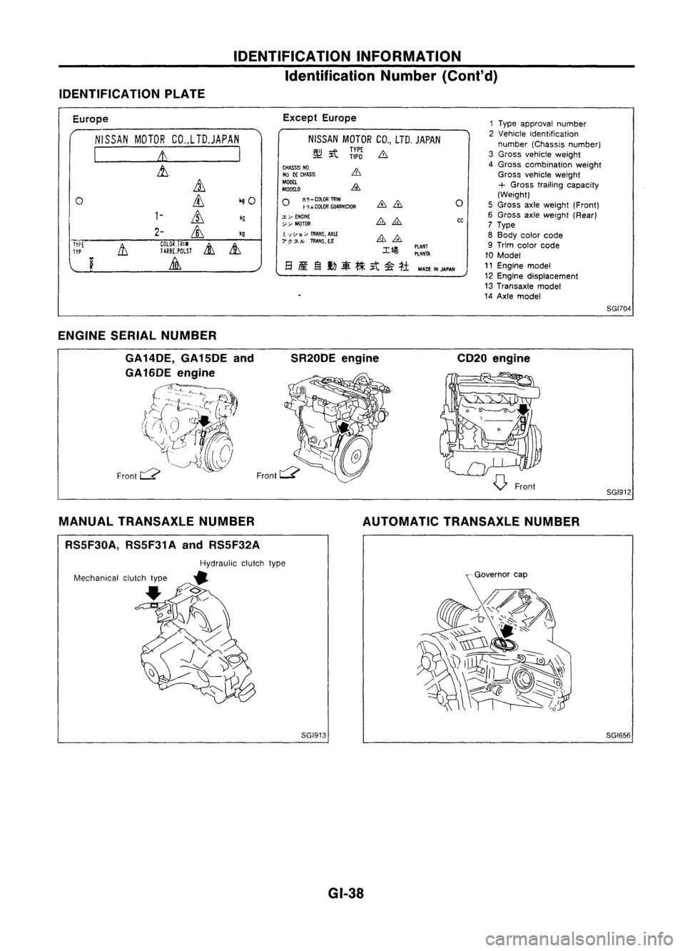
IDENTIFICATION PLATE
Europe
NISSAN MOTORCO.,LTD.JAPAN
I
It
I
&,
it
0
ill
iliO
1-
ill
kg
2-
&,
kg
Tri'[
11
COlOR.iRIM
&
&,
TYP
fARBE,POLSl
i
Lilli
Except
Europe
NISSAN MOTORCO.,LTD. JAPAN
~ it
ii:J
b
CHASS~ NO
NO DECHASIS
MODEL
MDDELO
o
~;::~:~~NlctDN
.:t;..-
ENGINE
~:,... MOTOR
~ ';;Y
3;..-
TRANS~
AXl.£
7P;;<'.
ll!AIIS.EJt:
M4DEINJAPAN
o
CC
1
Type approval number
2 Vehicle identification
number (Chassis number)
3 Gross vehicle weight
4 Gross combination weight
Gross vehicle weight
+
Gross trailing capacity
(Weight)
5 Gross axleweight (Front)
6 Gross axleweight (Rear)
7 Type
8 Body colorcode
9 Trim color code
10 Model
11 Engine model
12 Engine displacement
13 Transaxle model
14 Axle model
SGI704
ENGINE SERIALNUMBER
GA 14DE, GA15DE and
GA16DE engine
£~b-=~~rrf~)
(J~~~6
Front
c:::?
SR20DE
engine CD20engine
SGI912
MANUAL TRANSAXLE NUMBER
RS5F30A, RS5F31AandRS5F32A AUTOMATIC
TRANSAXLE NUMBER
SGI913 GI-38 SGI656
Page 1393 of 1701
IDENTIFICATIONINFORMATION
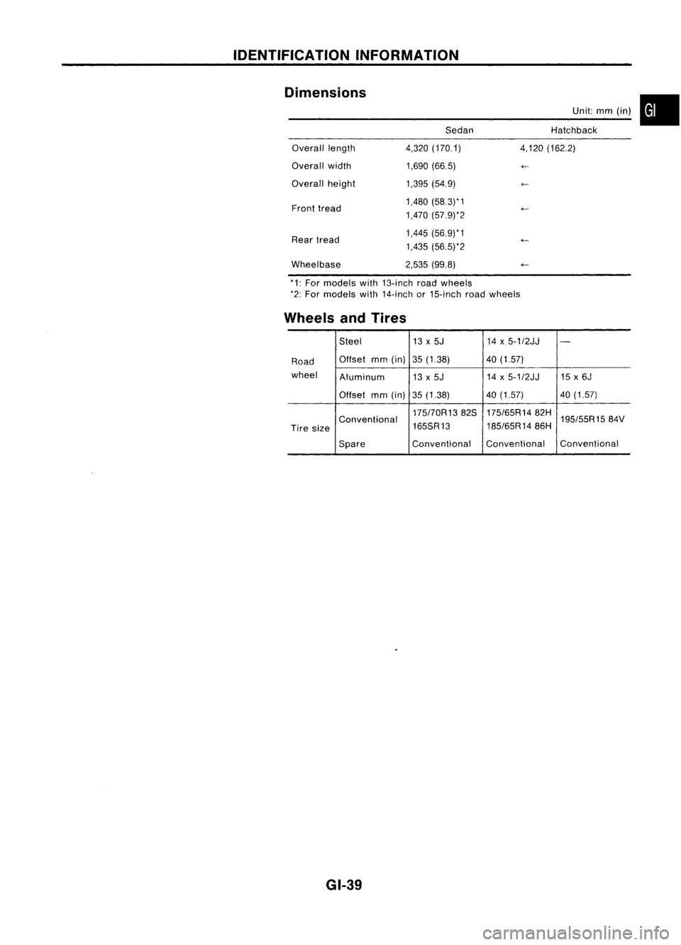
Dimensions SedanUnit:
mm(in) •
Hatchback
Overall length
Overall width
Overall height
Front tread
Rear tread
Wheelbase 4,320
(170.1)
1,690 (66.5)
1,395 (54.9)
1,480 (58.3)* 1
1,470 (57.9)*2
1,445 (56.9)*1
1,435 (56.5)*2
2,535 (99.8) 4,120
(162.2)
*1: For models with13-inch roadwheels
*2: For models with14-inch or15-inch roadwheels
Wheels andTires
Steel 13x5J 14x5-1/2JJ
-
Road Offset
mm(in) 35(1.38) 40(1.57)
wheel Aluminum 13x5J 14
x5-1/2JJ 15x6J
Offset mm(in)
35(1.38) 40
(1.57) 40(1.57)
175170R1382S 175/65R1482H
195/55R1584V
Conventional
185/65R1486H
Tire size 165SR13
Spare Conventional
Conventional Conventional
GI-39
Page 1394 of 1701
LIFTINGPOINTSANDTOW TRUCK TOWING
Preparation
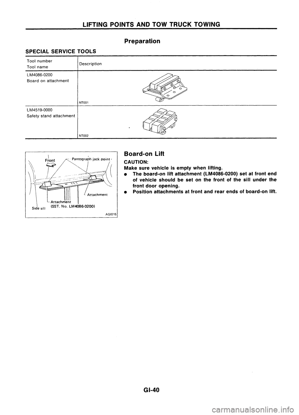
SPECIAL SERVICE TOOLS
Tool number
Tool name
LM4086-0200
Board onattachment
LM4519-0000
Safety standattachment Description
NT001
NT002
\
'\ Front
\\ F
\\1_ L.--
<
'f- --
r\-=-
Attachment
Attachment
Side sill ISST. No.LM40B6.0200)
AGI016Board-on
Lift
CAUTION: Make surevehicle isempty whenlifting.
• The board-on
lift
attachment (LM4086-0200) setatfront end
of vehicle shouldbeset onthe front ofthe sillunder the
front dooropening.
• Position attachments atfront andrear ends ofboard-on lift.
GI-40
Page 1395 of 1701
LIFTINGPOINTSANDTOW TRUCK TOWING
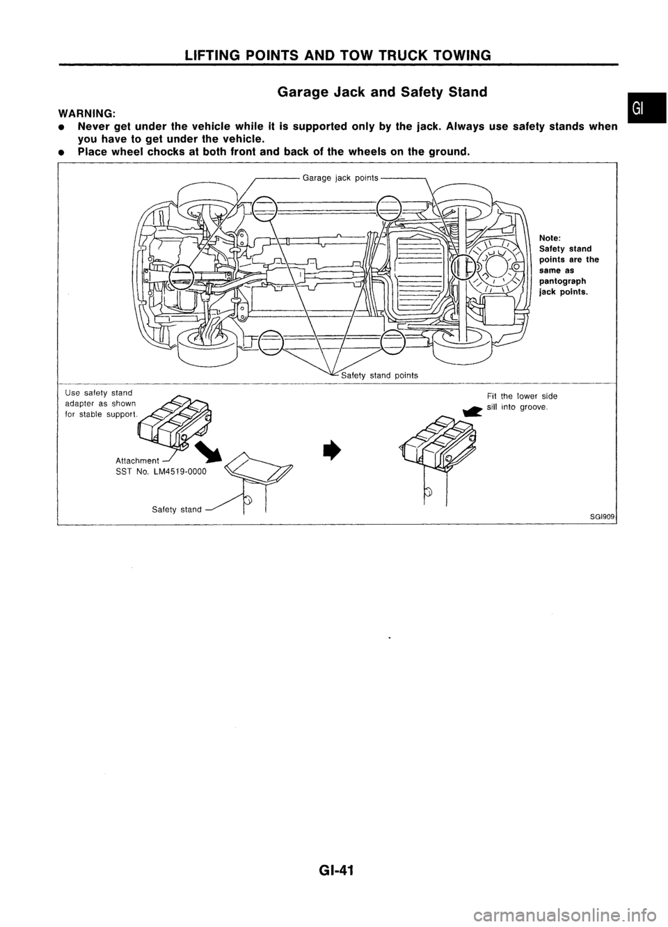
Garage JackandSafety Stand
WARNING:
• Never getunder thevehicle whileitis supported onlybythe jack. Always usesafety stands when
you have toget under thevehicle.
• Place wheel chocks atboth front andback ofthe wheels onthe ground.
•
Safety stand
8GI909
Note:
Safety stand
points arethe
same as
pantograph
jack points.
Garage
jackpoints
Attachment SST No.LM4519.0000
Use
safety stand
adapter asshown
for stable support.
GI-41
Page 1396 of 1701
LIFTINGPOINTSANDTOW TRUCK TOWING
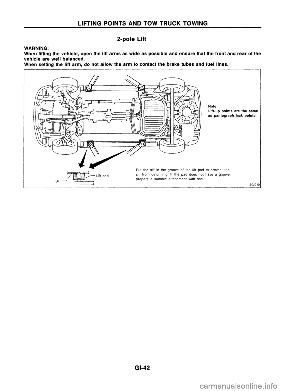
2-pole
Lift
WARNING:
When liftingthevehicle, openthe
lift
arms aswide aspossible andensure thatthefront andrear ofthe
vehicle arewell balanced.
When setting the
lift
arm, donot allow thearm tocontact thebrake tubesandfuel lines.
~LiftPad
Sill ~ ~__ ~ ~..
~---
Note:
Lift-up pointsarethesame
as pantograph jackpoints.
Put thesillinthe groove ofthe 11ftpad toprevent the
sill from deforming. Ifthe pad does nothave agroove,
prepare asuitable attachment withone.
8GI910
GI-42
Page 1397 of 1701
LIFTINGPOINTSANDTOW TRUCK TOWING
~ SGI80S
Automatic transaxlemodel
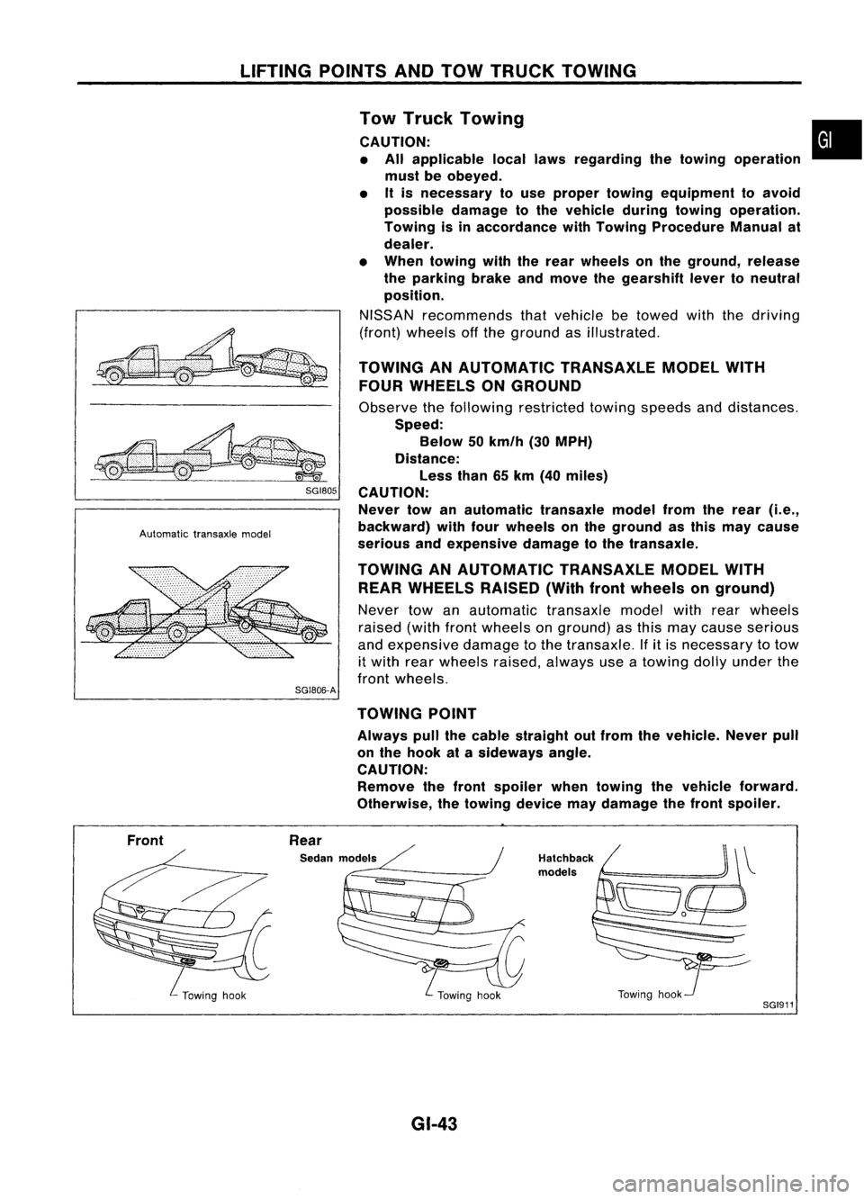
SG1806-A Tow
Truck Towing •
CAUTION: • All applicable locallawsregarding thetowing operation
must beobeyed.
• Itis necessary touse proper towing equipment toavoid
possible damagetothe vehicle duringtowing operation.
Towing isinaccordance withTowing Procedure Manualat
dealer.
• When towing withtherear wheels onthe ground, release
the parking brakeandmove thegearshift levertoneutral
position.
NISSAN recommends thatvehicle betowed withthedriving
(front) wheels offthe ground asillustrated.
TOWING ANAUTOMATIC TRANSAXLEMODELWITH
FOUR WHEELS ONGROUND
Observe thefollowing restricted towingspeeds anddistances.
Speed: Below 50km/h (30MPH)
Distance: Less than65km (40 miles)
CAUTION: Never towanautomatic transaxlemodelfromtherear
(i.e.,
backward) withfourwheels onthe ground asthis may cause
serious andexpensive damagetothe transaxle.
TOWING ANAUTOMATIC TRANSAXLEMODELWITH
REAR WHEELS RAISED(Withfrontwheels onground)
Never towanautomatic transaxlemodelwithrearwheels
raised (withfrontwheels onground) asthis may cause serious
and expensive damagetothe transaxle. Ifitis necessary totow
it with rearwheels raised,always useatowing dollyunder the
front wheels.
TOWING POINT
Always pullthecable straight outfrom thevehicle. Neverpull
on the hook atasideways angle.
CAUTION: Remove thefront spoiler whentowing thevehicle forward.
Otherwise, thetowing devicemaydamage thefront spoiler.
Front Rear
Sedan models
GI-43
Hatchback
models
Towinghook
SGI911
Page 1398 of 1701
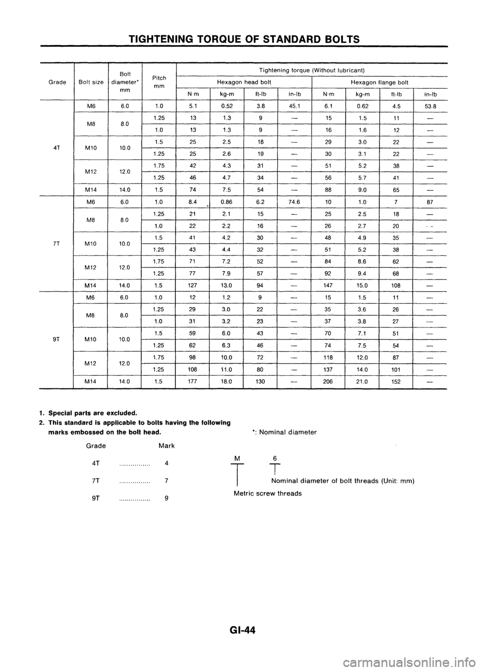
TIGHTENINGTORQUEOFSTANDARD BOLTS
Bolt Tightening
torque(Without lubricant)
Pitch
Grade Boltsize diameter' Hexagonheadbolt
Hexagonflangebolt
mm
mm
N'mkg-m
ft-Ibin-Ib
N'mkg-m
ft-Ib
in-Ib
M6 6.0 1.05.1
0.52 3.845.1 6.10.62
4.553.8
1.25 131.3
9
-
15
1.5 11
-
M8 8.0
1.0 131.3
9
-
16
1.6
12
-
1.5 252.5
18
-
293.0
22
-
4T M10 10.0
1.25 252.6
19
-
303.1
22
-
1.75 424.3
31
-
515.2
38
-
M12 12.0
1.25 464.7 34
-
5657 41
-
M14 14.0
1.574
7.5
54
-
889.0
65
-
M6 6.0
1.08.40.86 6.274.6 101.0
787
.
1.25 21
2.1 15
-
252.5 18
-
M8 80
1.0 22
2.2
16
-
262.7 20
.
-
1.5 41
4.2
30
-
484.9
35
-
7T M10 10.0
1.25 434.4
32
-
515.2
38
-
1.75 71
7.2
52
-
84
8.6 62
-
M12 12.0
1.25 777.9
57
-
929.4
68
-
M14 14.0 1.5127
13.0 94
-
147
15.0 108
-
M6 6.0
1.0 12
1.2
9
-
15
1.5 11
-
1.25 293.0
22
-
353.6
26
-
M8 8.0
1.0 313.2
23
-
37
3.8 27
--
1.5 596.0 43
-
70
7.1 51
-
9T M10 10.0
1.25 626.3
46
-
74
7.5 54
-
1.75 9810.0 72
-
118
12.0
87
-
M12 12.0
1.25 10811.0
80
-
137
14.0
101
-
M14 14.0
1.5177
18.0
130
-
206 21.0
152
-
1. Special parisareexcluded.
2. This slandard isapplicable 10bolls having thefollowing
marks embossed onthe boll head. *:
Nominal diameter
Grade
4T
7T
Mark
4
7 M
T
6
T
Nominal diameter ofbolt threads (Unit:mm)
9T 9
Metric
screwthreads
GI-44
Page 1399 of 1701
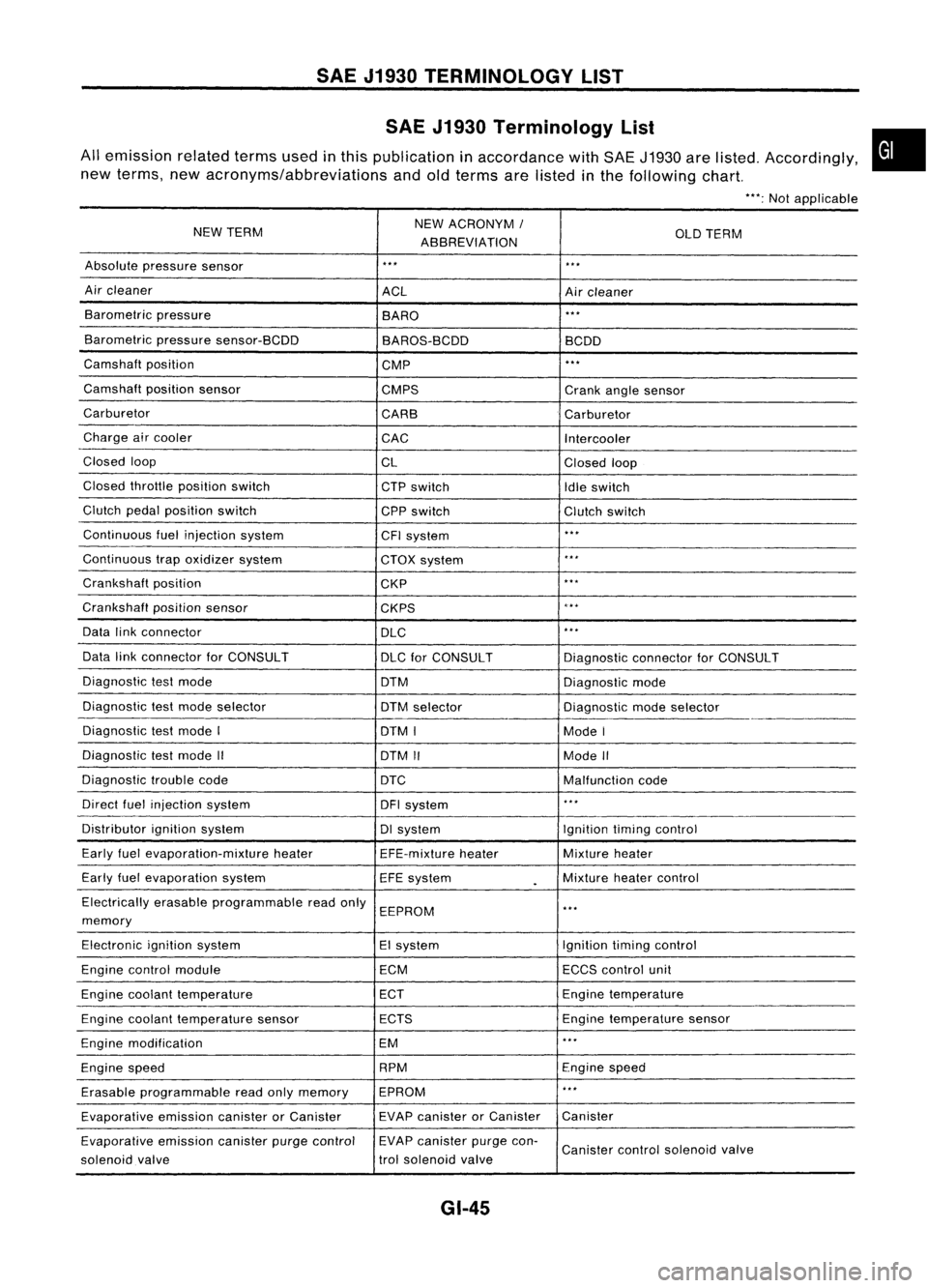
SAEJ1930 TERMINOLOGY LIST
SAE J1930 Terminology List
All emission relatedtermsusedinthis publication inaccordance withSAE J1930 arelisted. Accordingly,
new terms, newacronyms/abbreviations andoldterms arelisted inthe following chart.
"':Not applicable
NEW TERM NEW
ACRONYM /
ABBREVIATION OLD
TERM
Absolute pressure sensor
'" '"
Air cleaner
ACLAircleaner
Barometric pressure
BARO
."
Barometric pressuresensor-BCDD
BAROS-BCDD BCDD
Camshaft position
CMP
'"
Camshaft positionsensor
CMPS Crankanglesensor
Carburetor CARBCarburetor
Charge aircooler
CACIntercooler
Closed loop
CLClosedloop
Closed throttle position switch
CTPswitch
Idleswitch
Clutch pedalposition switch
CPPswitch Clutchswitch
Continuous fuelinjection system
CFIsystem
'"
Continuous trapoxidizer system
CTOXsystem
...
Crankshaft position
CKP
'"
Crankshaft positionsensor
CKPS
~.**
Data linkconnector
DLC
,
..
Data linkconnector forCONSULT
DLCforCONSULT DiagnosticconnectorforCONSULT
Diagnostic testmode
DTMDiagnosticmode
Diagnostic testmode selector
DTMselector Diagnosticmodeselector
Diagnostic testmode I
DTMI ModeI
Diagnostic testmode II
DTMII ModeII
Diagnostic troublecode
DTC Malfunctioncode
Direct fuelinjection system
DFIsystem
..
,
Distributor ignitionsystem DIsystem Ignitiontimingcontrol
Early fuelevaporation-mixture heater
EFE-mixtureheater Mixture
heater
Early fuelevaporation system
EFEsystem
.
Mixture
heatercontrol
Electrically erasableprogrammable readonly
EEPROM
'"
memory
Electronic ignitionsystem EIsystem Ignitiontimingcontrol
Engine control module ECMECCScontrol unit
Engine coolant temperature ECTEngine
temperature
Engine coolant temperature sensor ECTS Engine
temperature sensor
Engine modification EM
'"
Engine speed RPM
Enginespeed
Erasable programmable readonlymemory EPROM
'"
Evaporative emissioncanisterorCanister EVAP
canister orCanister Canister
Evaporative emissioncanisterpurgecontrol EVAP
canister purgecon-
Canister controlsolenoid valve
solenoid valve trol
solenoid valve
GI-45
•
Page 1400 of 1701
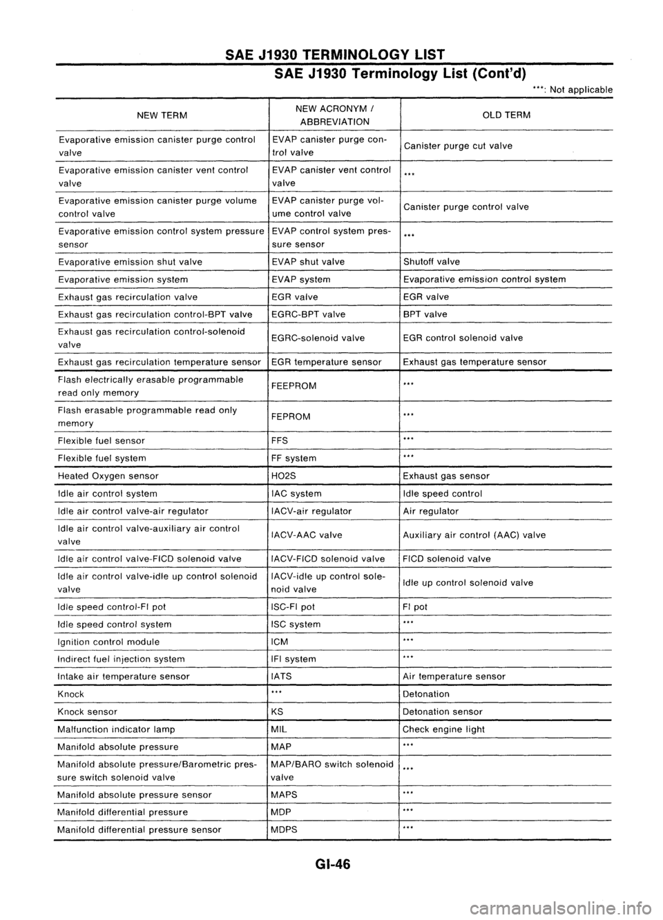
SAEJ1930 TERMINOLOGY LIST
SAE J1930 Terminology List(Cont'd)
***:
Not applicable
NEW TERM NEW
ACRONYM /
OLDTERM
ABBREVIATION
Evaporative emissioncanisterpurgecontrol EVAPcanister purgecon-
Canister purgecutvalve
valve trol
valve
Evaporative emissioncanisterventcontrol EVAPcanister ventcontrol
***
valve valve
Evaporative emissioncanisterpurgevolume EVAPcanister purgevol-
Canister purgecontrol valve
control valve ume
control valve
Evaporative emissioncontrolsystem pressure EVAP
control system pres-
***
sensor suresensor
Evaporative emissionshutvalve EVAP
shutvalve Shutoffvalve
Evaporative emissionsystem EVAPsystem Evaporative
emissioncontrolsystem
Exhaust gasrecirculation valve EGR
valve EGRvalve
Exhaust gasrecirculation control-BPTvalveEGRC-BPT valve BPT
valve
Exhaust gasrecirculation control-solenoid
EGRC-solenoidvalveEGR
control solenoid valve
valve
Exhaust gasrecirculation temperaturesensorEGRtemperature sensorExhaustgastemperature sensor
Flash electrically erasableprogrammable
FEEPROM
***
read onlymemory
Flash erasable programmable readonly
FEPROM
**.
memory
Flexible fuelsensor FFS
***
Flexible fuelsystem
FFsystem
***
Heated Oxygen sensor H02SExhaustgassensor
Idle aircontrol system lACsystem Idlespeed control
Idle aircontrol valve-air regulator IACV-airregulator Airregulator
Idle aircontrol valve-auxiliary aircontrol
IACV-AACvalve Auxiliaryaircontrol (AAC)valve
valve
Idle aircontrol valve-FICO solenoidvalve
IACV-FICDsolenoidvalve FICOsolenoid valve
Idle aircontrol valve-idle upcontrol solenoid IACV-idleupcontrol sole-
Idleupcontrol solenoid valve
valve noidvalve
Idle speed control-FI pot ISC-FIpot FIpot
Idle speed control system ISCsystem
***
Ignition controlmodule ICM
***
Indirect fuelinjection system IFIsystem
***
Intake airtemperature sensor IATS Airtemperature sensor
Knock
***
Detonation
Knock sensor
KSDetonation
sensor
Malfunction indicatorlamp MIL
Checkengine light
Manifold absolutepressure MAP
***
Manifold absolutepressure/Barometric pres-MAP/BARO switchsolenoid
***
sure switch solenoid valve valve
Manifold absolutepressure sensor MAPS
**.
Manifold differential pressure MOP
***
Manifold differential pressuresensor MOPS
***
GI-46