NISSAN ALMERA N15 1995 Service Manual
ALMERA N15 1995
NISSAN
NISSAN
https://www.carmanualsonline.info/img/5/57349/w960_57349-0.png
NISSAN ALMERA N15 1995 Service Manual
Trending: audio, service indicator, EC-301, wheelbase, wheel, maintenance schedule, hood open
Page 311 of 1701
ANTI-LOCKBRAKESYSTEM
Removal andInstallation (Cont'd)
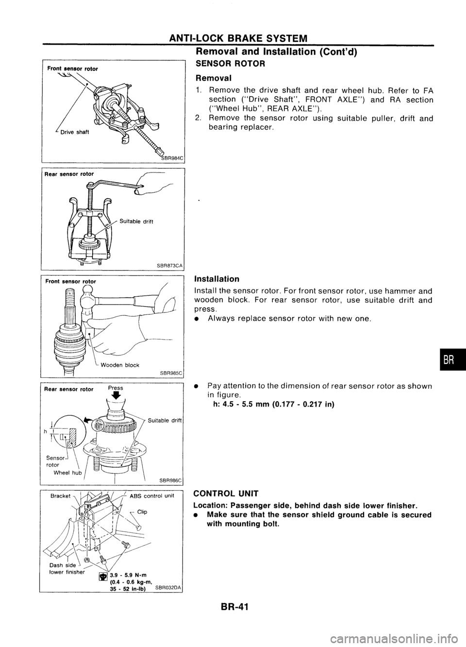
SENSOR ROTOR
Removal
1. Remove thedrive shaftandrear wheel hub.Refer toFA
section ("DriveShaft",FRONTAXLE") andRAsection
("Wheel Hub",REARAXLE").
2. Remove thesensor rotorusing suitable puller,driftand
bearing replacer.
Suitable drift
SBR873CA
Installation
Install thesensor rotor.Forfront sensor rotor,usehammer and
wooden block.Forrear sensor rotor,usesuitable driftand
press.
• Always replace sensorrotorwithnewone.
SBR985C
•
• Pay attention tothe dimension ofrear sensor rotorasshown
in figure.
h: 4.5 -5.5 mm (0.177 -0.217 in)
CONTROL UNIT
Location: Passenger side,behind dashsidelower finisher.
• Make surethatthesensor shieldground cableissecured
with mounting bolt.
SBR986C
Suitable
drift
B,.,k" ~ ABS
.'0"'" ","
Dash side ~
lower finisher ~3.9_5.9 N.m
(0.4 -0.6 kg-m,
35 -52 In-Ib)
SBR032DA
Rear
sensor rotor
BR-41
Page 312 of 1701
,ryside
linder prima
From master cy ndaryside
r
der seco
master cyIn
From
RHO
cc:J
11-15 .11)
(1.1 .
1.5, 8
~ Front
LHO
ASS
relay
box
ground
Actuator
cable
---------~~~~~:A~K~EirS;V~S~T~EWo.M;(c:O;;~'diij)I----
ANTI-LOCK
BRdInstallation (Cont
Removal an
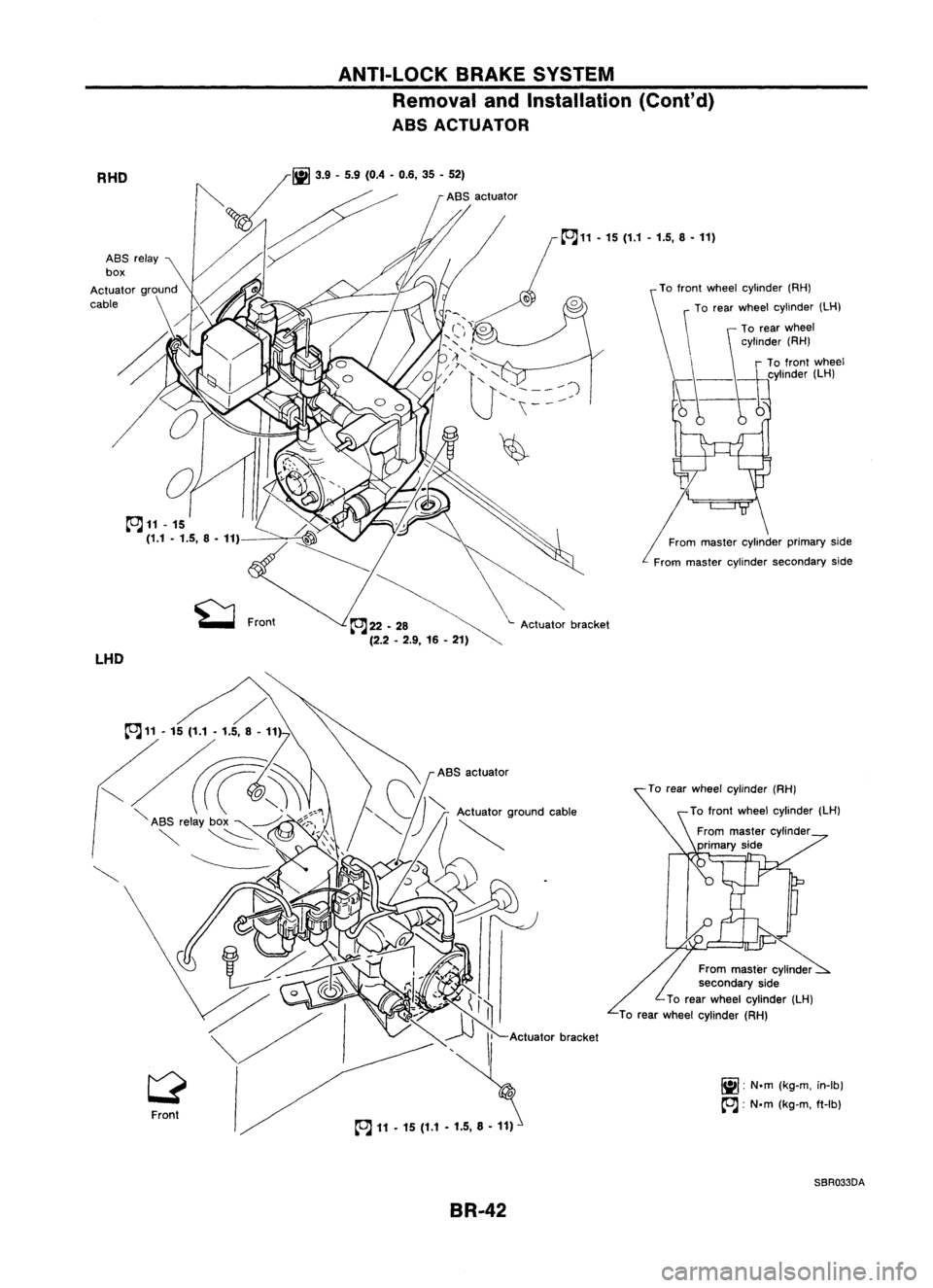
ABS ACTUATOR
heelcylinder (RH)
To rear
W
clinder (LH)
f ntwheel y
To ro
aster cylinder
From m
primary side
aster cylinder
From m 'de
secondary
Sl
(LH)
Wheel cylinder
To rear
W
heel cylinder (RH)
To
rear
(kg-m.in-Ib)
r.ii1
'N.m
IX! '
(kg-m. ft-Ib)
cc:J:
N.m
SBR033DA
BR-42
Page 313 of 1701
ANTI-LOCKBRAKESYSTEM
Removal andInstallation (Cont'd)
1. Disconnect batterycable.
2. Drain brake fluid.Refer toSR-5.
3. Discharge airconditioner refrigerant.RefertoHA section
("R-134a ServiceProcedure", "SERVICEPROCEDURES").
4. Disconnect allconnectors fromASSrelay bracket.
5. Remove mounting boltforrelay bracket.
6. Remove ASSrelay boxwith bracket.
7. Remove airconditioner low-pressure tubes.RefertoHA
section, ("Refrigerant Lines","SERVICE PROCEDURES") .
8. Disconnect brakepipesandmove awayfromactuator.
It is not necessary toremove thesepipesfromvehicle.
9. Remove/loosen mountingnutsbetween actuatorand
bracket.
BR-43
•
Page 314 of 1701
ANTI-LOCKBRAKESYSTEM
Removal andInstallation (Cont'd)
10. Draw outASS actuator asshown.
ASS
actuator
SBR039D CAUTION:
After installation, payattention tothe following points:
• Refill brake fluidandbleed air.Refer to"CHECK AND
ADJUSTMENT", BR-5and"AIR BLEEDING", BR.6,respec-
tively.
• Charge airconditioner refrigerant.RefertoHA section,
("R-134a ServiceProcedure", "SERVICEPROCEDURES").
• The installation procedureisthe reverse ofremoval.
ASS
actuator
_-=--=--=--=--_-_-\,_~
""'~t"
b"ok.,
SBR040D
ABSRELAYS
1. Disconnect batterycable.
2. Remove ASSrelay cover.
BR-44
Page 315 of 1701
ANTI-LOCKBRAKESYSTEM
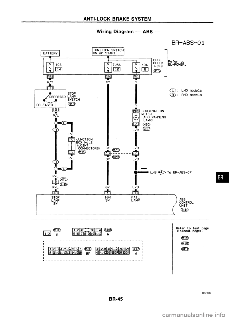
Wiring Diagram -ABS -
BR-ABS-01
•
ABS
CONTROL
UNIT
(B111)
LHDmodels
@:
RHOmodels
Refer
to
EL-POWER.
FUSE
BLOCK
(JIB)
~
GY
ffi
IGN
SW
Y
I~I COMBINATION
METER
(ABS WARNING
LAMP)
~@
LIB
@
I
GY
LIB
$-------$
GY (~) LIB
I-
e-
LIB~ ToBR-ABS-O?
I
LIB
13-0
I
FAIL
LAMP
IGNITION
SWITCH
ON orSTART
STOP
DEPRESED LAMP
SWITCH
RELEASED ~
~
P!L
•
~:I
P!L
rn~
I
JUNCTION
BOX
NO.2
(JOINT
CONNECTORS)
1!:i=!J~
PIL
~~
•
PIL
lelIl
9F'~
P!L
14-81
STOP
LAMP
SW
Fa~
l..1..@
B ~~(B115)
5 6
TI1910
1112 W
Refer
tolast page
(Foldout page).
~---------------------------------,
L ~
HBR002
BR-45
Page 316 of 1701
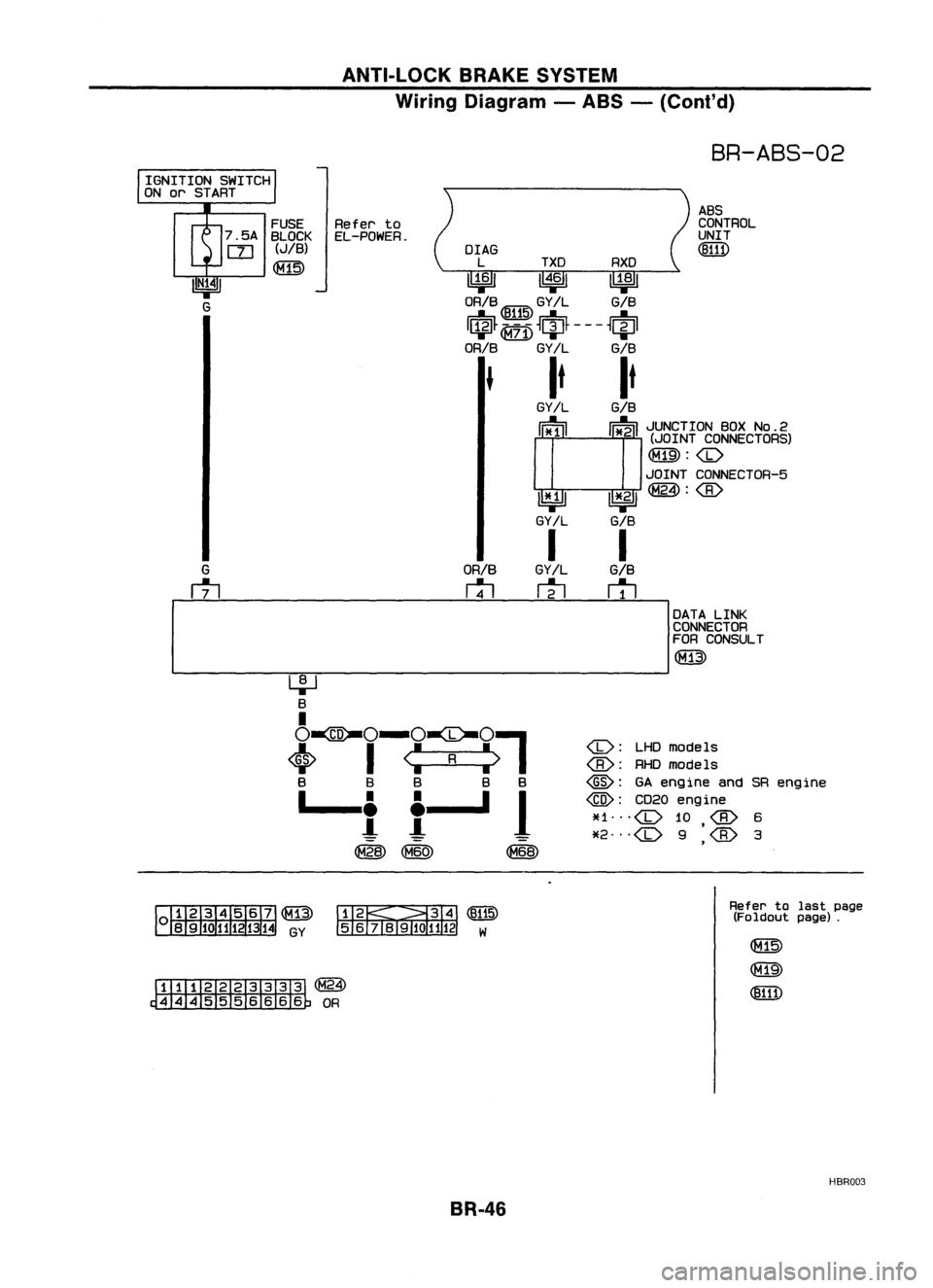
ANTI-LOCKBRAKESYSTEM
Wiring Diagram -ABS -(Coni' d)
BR-ABS-02
ABS
CONTROL
UNIT
(!ID1)
OrAG
L TXD RXD
~ 1~61~
ORIB ~ GY!L GIB
I$~ ~
~ciJ~ ---
~~I
ORIB
GY/L GIB
It It
GY!L
GIB
cr
l I~
i~MO~o~?ic~g~)
~:
JOINT CONNECTOR-5
~ 1*.21~:
GY/L GIB
I I
GY/L
GIB
m
r1l
ORIB
rtl
FUSE
Referto
7 .5A BLOCK EL-POWER.
rn
(JIB)
~
IGNITION
SWITCH
ON orSTART
I
DATALINK
CONNECTOR
FOR CONSULT
(M13)
-----------------------
<0:
LHDmodels
RHOmode Is
@:
GAengine andSRengine
@:
CD20engine
~f1
<0
10
6
*2
<0
9
'
3
,
~~(~)
56j819101112 W
~(~24)
~OR
Refer
tolast page
(Foldout page).
HBR003
BR-46
Page 317 of 1701
ANTI-LOCKBRAKESYSTEM
Wiring Diagram -ABS -(Cont'd)
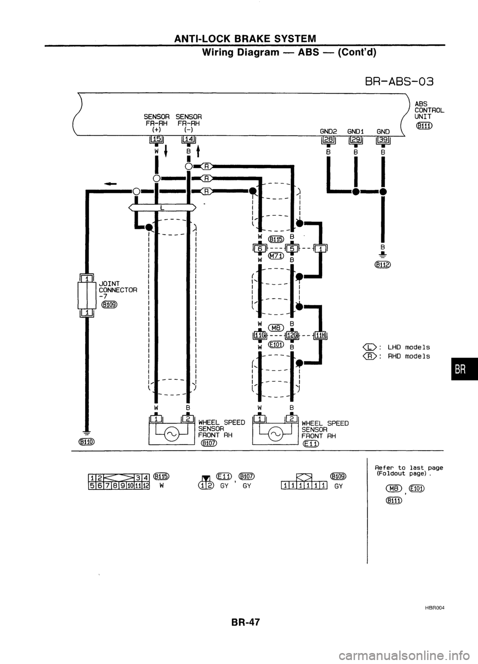
BR-ABS-03
•
ABS
CONTROL
UNIT
LHO models
RHO models
(jJ:
(8):
GN02
GNO1 GNO
12.81 12.911
3•
9
1
B BB
Ll-l
I
----
)
I
1
I
1
----
']
W@1IDB .
$---$-]1
W
@)
8
-----
(,
-
_.
1 -- I
I I
I I
l.... •
l~t~~8}j~f
-]1
W «(1Q"n B
-----
r-- _
I I
I 1
1 1
l....
'J
R
R
~
..
1
1
I
I
I ....
l
SENSOR
FR-RH
H
~
B
t
I
o
,. 1
1
1
I
I
I
I
1
I
I
1
I
J 1
1
I
1
1
I
I
1
1
1
1
1
I
1
I ....
t
-
rn
JOINT
CONNECTOR
-7
(B109)
1
WB
~ WHEELSPEED
SENSOR
rv
FRONTRH
(1llQj)
W
B
M
WHEELSPEED
SENSOR
rv
FRONTRH
(E 11)
&~(BIT5)
5 6TII9ID 1112W ..In
em),
@ill)
<..!J.g)
GYGY
~(Eli[9)
IIlIITl.IIillJ
GY
Refer
tolast page
(Foldout page).
HBR004
BR-47
Page 318 of 1701
ANTI-LOCKBRAKESYSTEM
Wiring Diagram -ABS -(Cont'd)
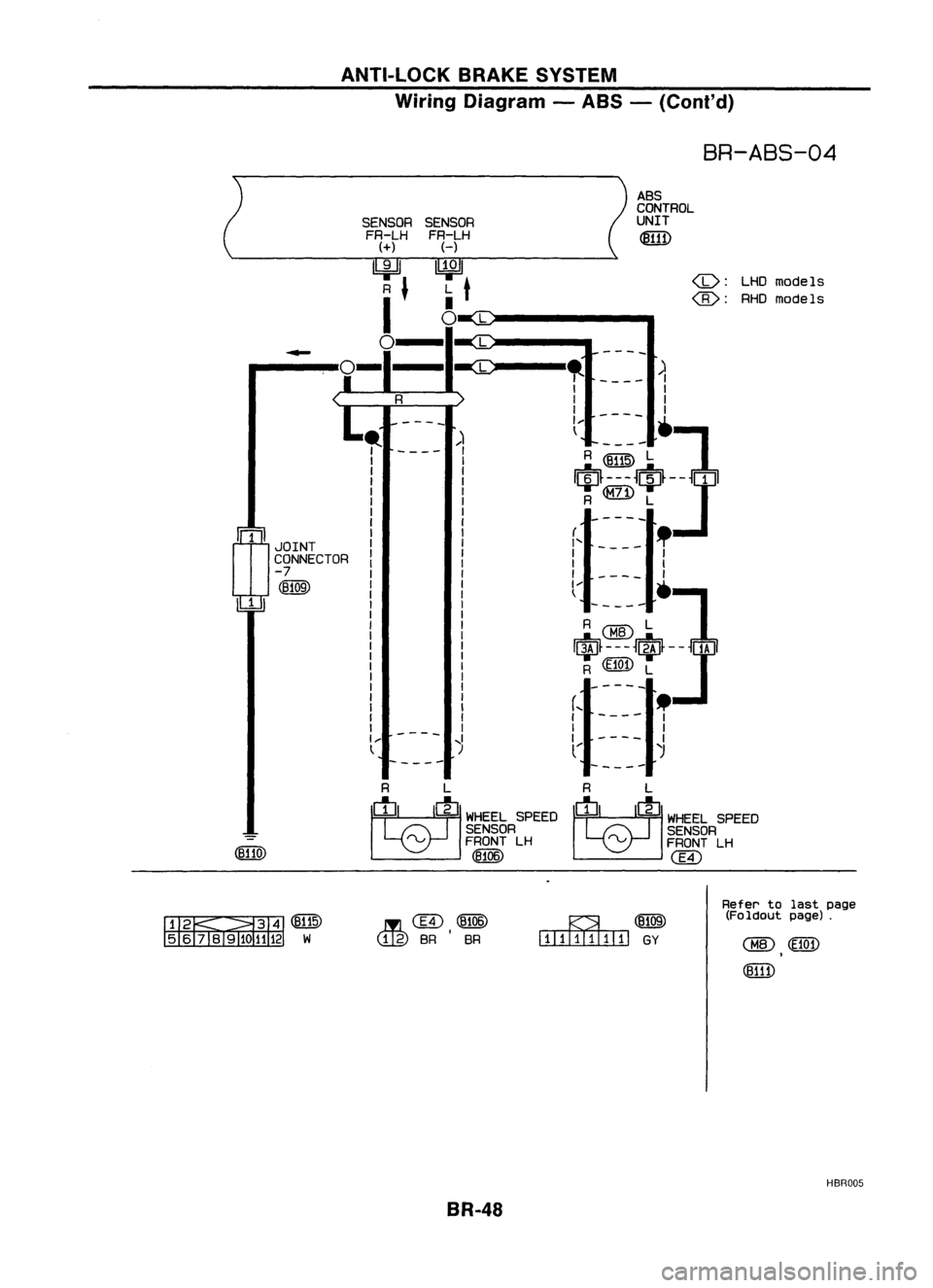
BR-ABS-04
ASS
CONTROL
SENSOR UNIT
FR-LH
~
H
~
LHO
models
L
t
•
@:
RHOmodels
0
L
L
-
-
-
--
-ec
,.
)
I
I
I
I
I
I
I
----
1--
']
)
t
----
I
R~ L
I
I
$---$J
I
I
R
L
1
1
-
-
--
I
mJOINT
I
I'-- --
!
I
1
CONNECTOR
I
I
I
-7
I
1
I
(B109)
l--•
1
-----
A@L ]
I$f---J$-J
R
(ffi1)
L
-----
(,
.
I I
-
---
1
I
I
I
--
,I
II
t
)
(
)
-----
-----
R L R
L
M
.>'EELSPEED
M
WHEEL
SPEED
SENSOR SENSOR
-
rvFRONTLH
rvFRONTLH
(eUO)
(8106)
@
~~(@
56 iBl91
...IE.
@,(~)
(tig)
SR SR
BR-48 ~(B109)
illIIIIIIIIIl
GY
Refer
tolast page
(Foldout page).
HBR005
Page 319 of 1701
ANTI-LOCKBRAKESYSTEM
Wiring Diagram -ABS -(Conl'd)
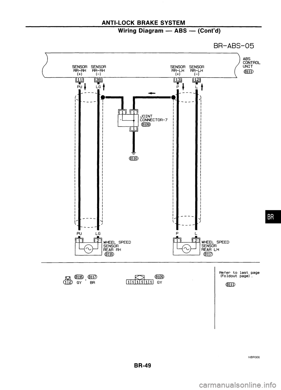
BR-ABS-05
-----
-----
A8S
CONTROL
UNIT
SENSOR
RR-LH
H
~ L
t
"
----
/)
I
I
I
I
I
I
I
I
I
SENSOR
RR-LH
(+)
lY;ll
P
J
r-:l~!
I
JOINT
I .
CONNECTOR-7
I
@QID
r
(8110)
SENSOR
RR-RH
H
1
3•8
1
LG
t
(
....
SENSOR
RR-RH
(+)
~ PU
J
----
'I
/
I
1
1
I
I
I
I
I
I
I
I
I
I
I
I
I
,I
)
•
PU LG
M
WHEELSPEED
SENSOR
rv REARRH
(!W)
P
L
M
WHEELSPEED
SENSOR
rv
REARLH
(ffi?)
15a
([UID ,
@TI)
C!J.g)
GYSR ~(8109)
l:TIIillIIIIIJ
GY
Refer
tolast page
(Foldout page).
HBR006
BR-49
Page 320 of 1701
ANTI-LOCKBRAKESYSTEM
Wiring Diagram -ABS -(Coni' d)
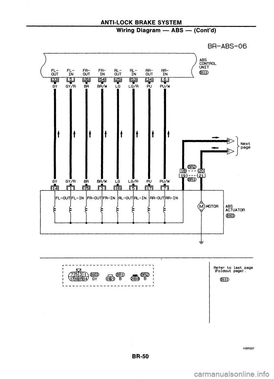
BR-ABS-06
ABS
CONTROL
UNIT
FL- FL-FR-
FR- RL-
RL-RR-
RR-
~
OUT INOUT
INOUT
INOUT IN
1
3';'
IbiJ
1
2•6
1
1
5•4
1
1
2';'
1
5•3
1
1
3•4
1
~
GY GY/R
BRBR/W
LGLG/R
PUPU/W
t tt
t tt tt
-
B
}Next
-
page
C
@
18 --- 20
19 --- 21
GY GY/R
BRBR/W
LGLG/R PUPU/W
~
nf4ll
m ~
rTI
wf6n
rrtll
Iff7il
~
FL -OUT FL-IN FR-OUT FR-IN RL-OUT RL-IN RR-OUT RR-IN
M
MOTOR ABS
ACTUATOR
(fJ103)
=
r-------------------------,
I
~~ ~@:
~ B~ B
I
I
L
~
BR-50
Refer
tolast page
(Foldout page).
HBRDD?
Trending: washer fluid, hood release, wipers, window, warning lights, overheating, roof rack
