NISSAN ALMERA N15 1995 Service Manual
Manufacturer: NISSAN, Model Year: 1995, Model line: ALMERA N15, Model: NISSAN ALMERA N15 1995Pages: 1701, PDF Size: 82.27 MB
Page 351 of 1701
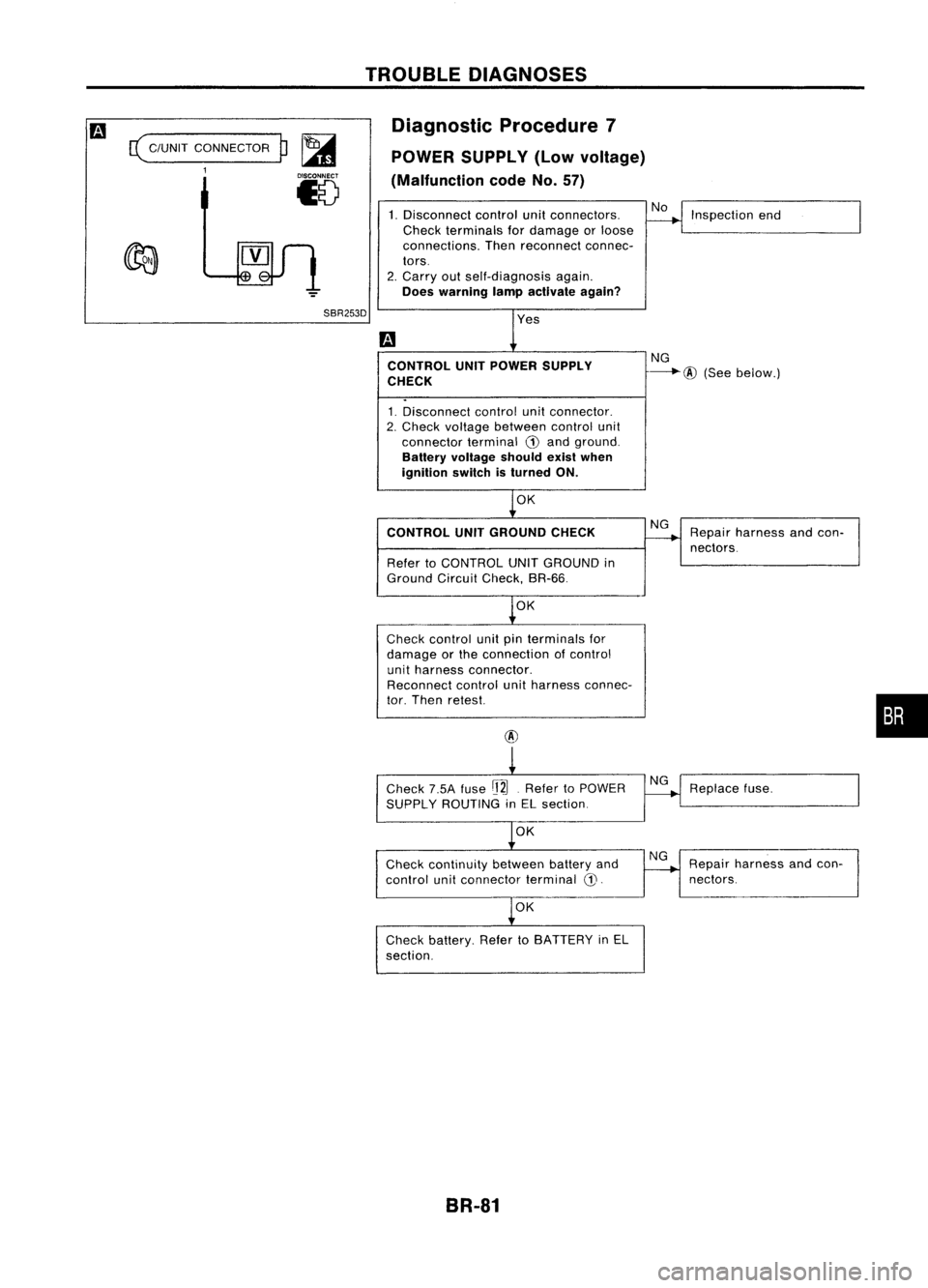
c(
C/UNIT CONNECTOR
1
p~
18
TROUBLE
DIAGNOSES
Diagnostic Procedure7
POWER SUPPLY (Lowvoltage)
(Malfunction codeNo.57)
1. Disconnect controlunitconnectors.
Check terminals fordamage orloose
connections. Thenreconnect connec-
tors.
2. Carry outself-diagnosis again.
Does warning lampactivate again? No
Inspection end
SBR253D CONTROL UNITPOWER SUPPLY
CHECK
1. Disconnect controlunitconnector.
2. Check voltage between controlunit
connector terminalG)and ground.
Battery voltage shouldexistwhen
ignition switchisturned ON.
OK NG
---.-.@
(Seebelow.)
CONTROL UNITGROUND CHECK
Refer toCONTROL UNITGROUND in
Ground CircuitCheck, BR-66.
OK
Check control unitpinterminals for
damage orthe connection ofcontrol
unit harness connector.
Reconnect controlunitharness connec-
tor. Then retest.
@
Check 7.5Afuse
rj2J.
Refer toPOWER
SUPPLY ROUTING inEL section.
OK
Check continuity betweenbatteryand
control unitconnector terminal
CD.
OK
Check battery. RefertoBATTERY inEL
section.
BR-81 NG
NG
NG Repair
harness andcon-
nectors.
Replace fuse.
Repa;, hame" aodcoo-
I
nectors.
•
Page 352 of 1701

TROUBLEDIAGNOSES
Diagnostic Procedure8
CONTROL UNIT
(Malfunction codeNo.71)
Carry outself-diagnosis aftererasing
self-diagnostic results,BR-56.
Does warning lampindicate codeNo.
71 again?
No
Inspect thesystem according tothe
code No. Yes
Replace controlunit.
Brake pedal Diagnostic
Procedure9
SYMPTOM: Pedalvibration andnoise
No
Does thesymptom appearwhenelectri-
SAT797A
calequipment switches(suchashead-
lamp) areoperated?
1.
Apply brake.
2. Start engine.
3. Does thesymptom appearonlywhen
engine isstarted?
No
Yes
Check wheelsensor shieldgrou.nd
secured withcontrol unitmounting bolt.
Refer toBR-41. Yes
Carryoutself-diagnosis.
Refer toBR-53 (Europe)
or BR-56 (Except
Europe).
Go to
Ii1
inDiagnostic
Procedure 11,BR-83.
OK
Check control unitpinterminals for
damage orthe connection ofcontrol
unit harness connector.
Reconnect controlunitharness connec-
tor. Then retest.
Note: ABSmayoperate andcause vibration underanyofthe
following conditions.
• Applying brakegradually whenshifting oroperating clutch.
• Low friction (slippery) road.
• High speed cornering.
• Driving overbumps andpotholes.
• Engine speedisover 5,000 rpmwith vehicle stopped.
BR-82
Page 353 of 1701

TROUBLEDIAGNOSES
Diagnostic Procedure10
SYMPTOM: Longstopping distance
Disconnect ABSrelay box6-pin connec- No
tor and check whether stopping dis-
tance isstill long.
Perform Preliminary Checkandair
bleeding. Go
to
IiJ
inDiagnostic
Procedure 11.SR-83.
Note: Stopping distancemaybelarger thanvehicles without
ABS when roadcondition isslippery.
Diagnostic Procedure11
SYMPTOM: Unexpected pedalaction
m
Check brakepedalstroke. Isstroke
excessively
large?
No
Disconnect ASSrelay box6-pin connec-
tor and check whether brakeiseffec-
SBR540A tive.
Yes
Ensure warning lampremains offwhile
driving.
OK
CHECK WHEEL SENSOR.
1. Check wheelsensor connector for
terminal damageorloose connec-
tion.
2. Perform wheelsensor mechanical
check. Refer to
IiJ
inDiagnostic Procedure
4, BR-75.
OK
Check control unitpinterminals for
damage orthe connection ofcontrol
unit harness connector.
Reconnect controlunitharness connec-
tor. Then retest.
BR-83
Yes
Perform Preliminary
Check. refertoSR-65.
Perform Preliminary
Check. refertoSR-65.
Carry outself-diagnosis.
Refer toBR-53 (Europe)
or SR-56 (Except
Europe).
Repair.
•
Page 354 of 1701
TROUBLEDIAGNOSES
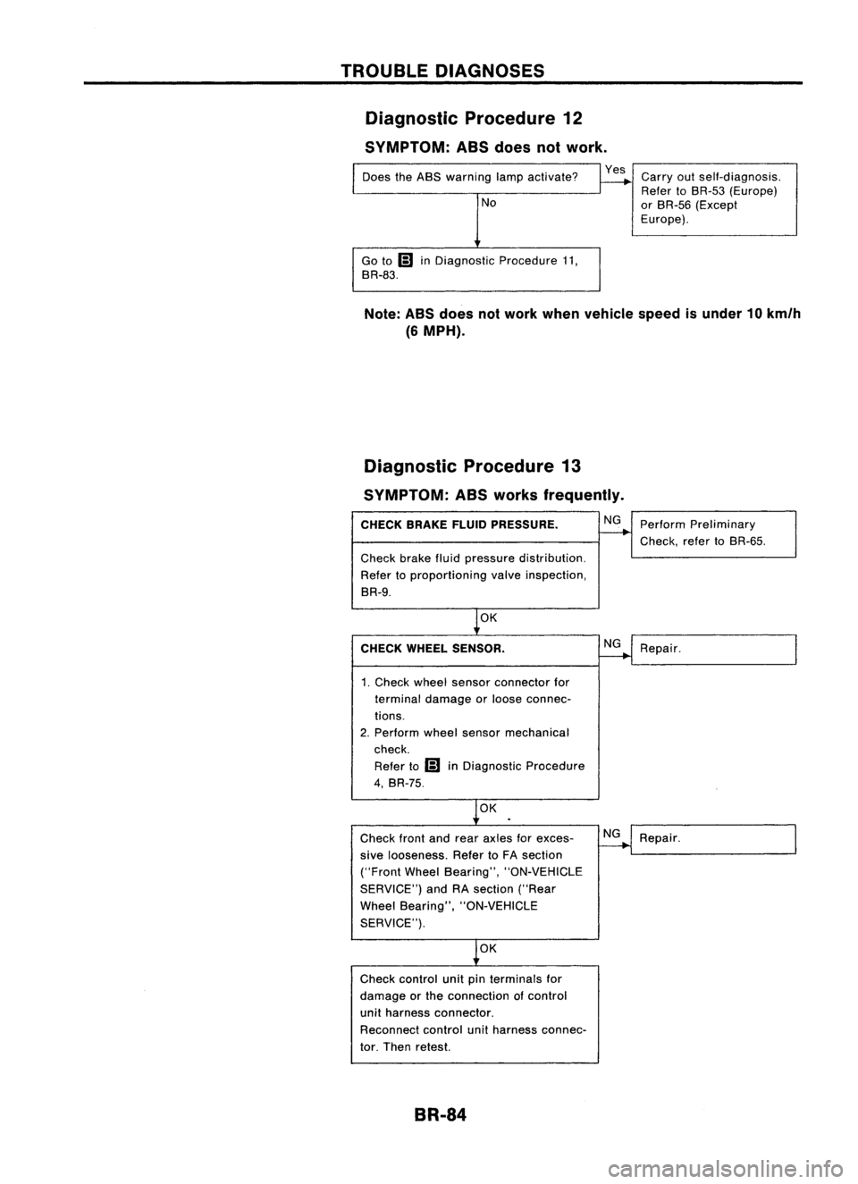
Diagnostic Procedure12
SYMPTOM: ASSdoes notwork.
Does theABS warning lampactivate?
No
Go to
Ii)
inDiagnostic Procedure11,
BR-83.
Yes
Carryoutself-diagnosis.
Refer toBR-53 (Europe)
or BR-55 (Except
Europe).
Note: ABSdoes notwork when vehicle speedisunder 10km/h
(6 MPH).
Diagnostic Procedure13
SYMPTOM: ASSworks frequently.
CHECK BRAKEFLUIDPRESSURE.
Check brakefluidpressure distribution.
Refer toproportioning valveinspection,
BR-9.
OK
CHECK WHEEL SENSOR.
1. Check wheelsensor connector for
terminal damage orloose connec-
tions.
2. Perform wheelsensor mechanical
check.
Refer to
Ii)
inDiagnostic Procedure
4, BR-75.
OK
Check frontandrear axles forexces-
sive looseness. RefertoFA section
("Front WheelBearing", "ON-VEHICLE
SERVICE") andRAsection ("Rear
Wheel Bearing", "ON-VEHICLE
SERVICE").
OK
Check control unitpinterminals for
damage orthe connection ofcontrol
unit harness connector.
Reconnect controlunitharness connec-
tor. Then retest.
BR-84 NG
NG
NG
Perform
Preliminary
Check, refertoBR-55.
Repair.
Repair.
Page 355 of 1701
TROUBLEDIAGNOSES
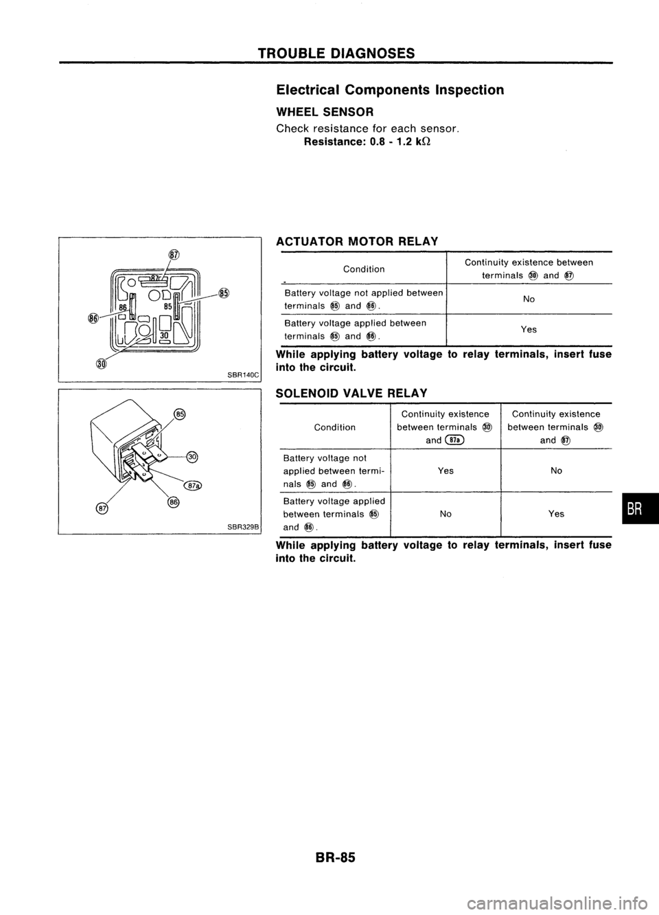
Electrical Components Inspection
WHEEL SENSOR
Check resistance foreach sensor.
Resistance: 0.8-1.2 kQ
ACTUATOR MOTORRELAY
While applying batteryvoltage torelay terminals, insertfuse
into thecircuit.
Condition
Battery voltage notapplied between
terminals
@
and
@.
Battery voltage applied between
terminals
@
and
@.
SBR140C
Continuity
existencebetween
terminals
@
and
@
No
Yes
SBR329B SOLENOID
VALVERELAY
Continuity existence Continuityexistence
Condition between
terminals
@
between terminals
@
and@ and
@
Battery voltage not
applied between termi- Yes
No
nals
@
and
@.
Battery voltage applied
between terminals
@
No Yes
and
@.
While applying batteryvoltage torelay terminals, insertfuse
into thecircuit.
BR-85
•
Page 356 of 1701
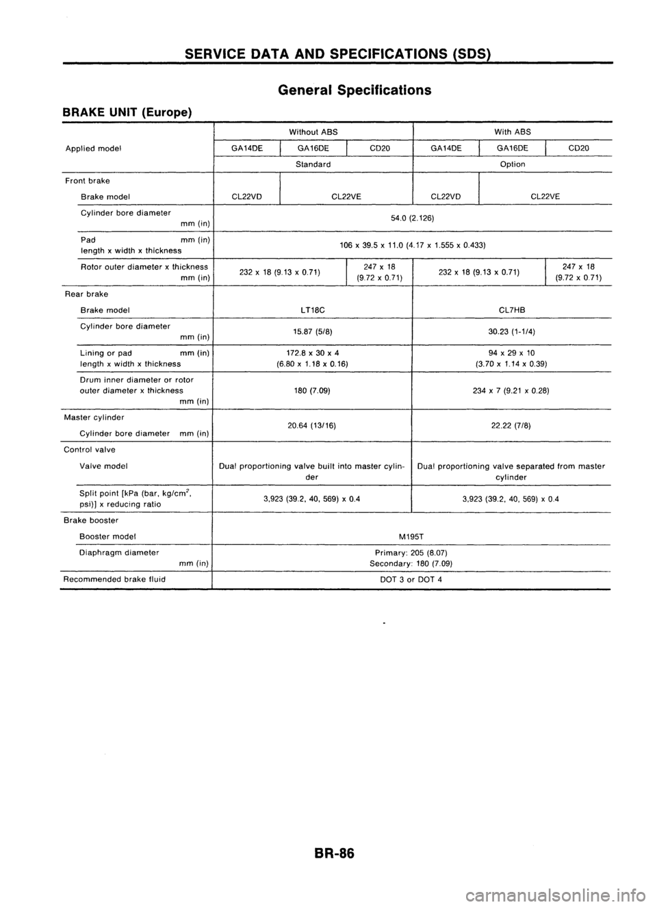
SERVICEDATAANDSPECIFICATIONS (SOS)
General Specifications
BRAKE UNIT(Europe)
WithoutABS WithABS
Applied model GA14DE
GA16DE
I
CD20
GA14DE GA16DE
I
CD20
Standard Option
Front brake
Brake model CL22VDCL22VECL22VD CL22VE
Cylinder borediameter
54.0(2.126)
mm (in)
Pad mm(in)
106x39.5 x11.0 (4.17 x1.555 x0.433)
length xwidth xthickness
Rotor outerdiameter xthickness
232x18 (9.13 x0.71)
I
247
x18
232x18 (9.13 x0.71)
I
247
x18
mm (in) (972x0.71) (9.72x0.71)
Rear brake
Brake model
LT18C CL7HB
Cylinder borediameter
15.87(5/8) 30.23(1-1/4)
mm (in)
Lining orpad mm
(in)
172.8x30 x4 94x29 x10
length xwidth xthickness (6.80x1.18 x0.16) (3.70x1.14 x0.39)
Drum innerdiameter orrotor
outer diameter xthickness 180(7.09) 234x7 (9.21 x0.28)
mm (in)
Master cylinder
20.64(13/16) 22.22(7/8)
Cylinder borediameter
mm(in)
Control valve
Valve model Dualproportioning valvebuiltintomaster cylin-
Dualproportioning valveseparated frommaster
der cylinder
Split point [kPa(bar. kg/cm
2•
3.923(39.2. 40.569) x0.4
3.923(39.2. 40.569) x0.4
psi)] xreducing ratio
Brake booster
Booster model
M195T
Diaphragm diameter
Primary:205(8.07)
mm (in)
Secondary:180(7.09)
Recommended brakefluid
DOT3or DOT 4
BR-86
Page 357 of 1701
SERVICEDATAANDSPECIFICATIONS (SDS)
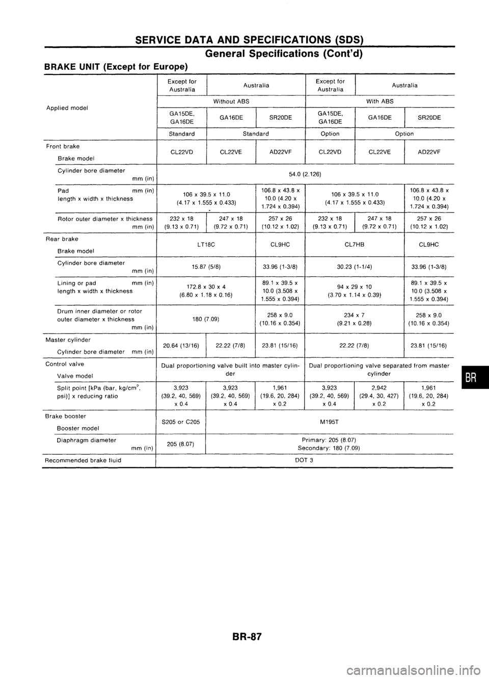
General Specifications (Cont'd)
BRAKE UNIT(Except forEurope)
Except for
Australia Except
for
Australia
Australia Australia
Without ABS With
ABS
Applied model
GA15DE.GA16DESR20DEGA15DE.
GA16DESR20DE
GA16DE GA16DE
Standard Standard Option
Option
Front brake
CL22VDCL22VE AD22VF
CL22VD CL22VEAD22VF
Brake model
Cylinder borediameter
54.0(2.126)
mm (in)
Pad mm
(in)
106x39.5 x11.0 106.8
x43.8 x
106x39.5x11.0 106.8
x43.8 x
length xwidth xthickness
(4.17x1.555 x0.433) 10.0
(4.20 x
(417x1.555 x0.433) 10.0
(4.20 x
.
1.724
x0.394)
1.724x0.394)
Rotor outerdiameter xthickness 232
x18 247x18 257x26 232x18 247
x18
257x26
mm (in) (9.13x0.71) (9.72
x0.71) (10.12x1.02) (9.13x0.71) (9.72x0.71) (10.12x1.02)
Rear brake
LT18CCL9HC CL7HB
CL9HC
Brake model
Cylinder borediameter
15.87(5/8) 33.96(1-3/8) 30.23(1-1/4) 33.96(1-3/8)
mm (in)
Lining orpad mm
(in)
172.8x30 x4 89.1
x39.5 x
94x29 x10 89.1
x39.5 x
length xwidth xthickness
(6.80x1.18 x0.16) 10.0
(3.508 x
(370x1.14 x0.39) 10.0
(3.508 x
1.555 x0.394)
1555x0.394)
Drum innerdiameter orrotor
258x9.0 234x7
258x9.0
outer diameter xthickness 180
(7.09)
(10.16x0.354) (9.21x0.28)
(10.16x0.354)
mm (in)
Master cylinder
20.64(13/16) 22.22
(7/8) 23.81(15/16) 22.22(7/8) 23.81(15/16)
Cylinder borediameter mm
(in)
Control valve
Dualproportioning valvebuiltintomaster cylin- Dualproportioning valveseparated frommaster
Valve model der
cylinder
Split point [kPa(bar.
kg/cm'.
3.923
3.923 1.9613.923 2.942
1.961
psi)] xreducing ratio (39.2.40.569) (39.2.40.569) (19.6.
20.284)
(39.2.40.569) (29.4.30.427) (19.6.20.284)
x 0.4 x0.4 x
0.2
x0.4 x
0.2
x0.2
Brake booster
S205orC205 M195T
Booster
model
Diaphragm diameter
205(8.07) Primary:
205(8.07)
mm (in) Secondary:180(7.09)
Recommended brakefluid DOT
3
BR-87
•
Page 358 of 1701
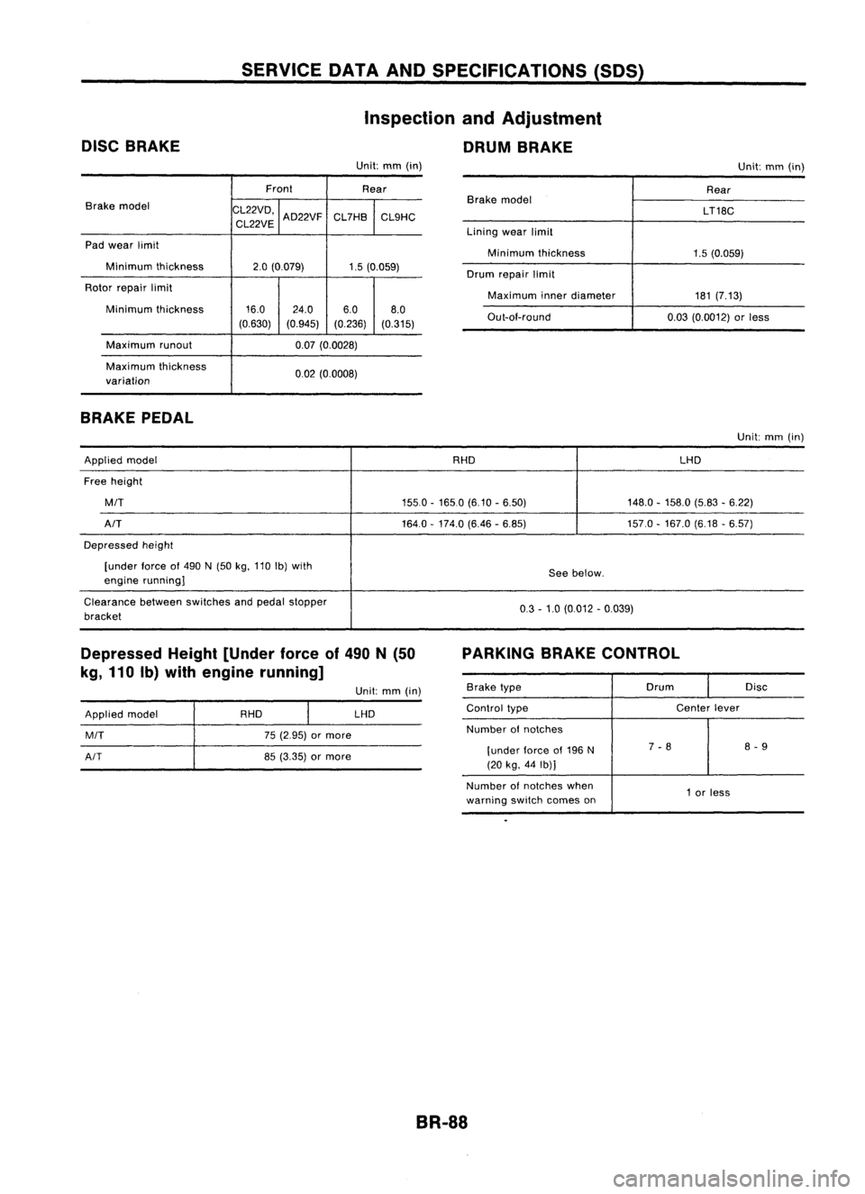
DISCBRAKE SERVICE
DATAANDSPECIFICATIONS (SDS)
Inspection andAdjustment
DRUM BRAKE
Unit: mm(in)
Unit:mm(in)
Front Rear
Brake model
CL22VD,
CL22VE AD22VF
CL7HB
CL9HC
Pad wear limit
Minimum thickness
2.0(0.079) 1.5(0.059)
Rotor repair limit
Minimum thickness 16.0
24.0 6.08.0
(0.630) (0.945) (0.236)(0.315)
Maximum runout 0.07(0.0028)
Maximum thickness
0.02(0.0008)
variation
BRAKE PEDAL
Brake
model
Lining wearlimit
Minimum thickness
Drum repair limit
Maximum innerdiameter
Out-ai-round Rear
LT18C
1.5 (0.059)
181 (7.13)
0.03 (0.0012) orless
Unit: mm(in)
Applied model RHDLHD
Free height
MIT
155.0-1650 (6.10-6.50) 148.0-158.0 (5.83-6.22)
AIT
164.0-174.0 (6.46-6.85) 157.0-167.0 (6.18-6.57)
Depressed height
[under force
01
490 N(50 kg,110 Ib)with
Seebelow.
engine running]
Clearance betweenswitches andpedal stopper
0.3-1.0 (0.012 -0.039)
bracket
Depressed Height[Under forceof490 N(50
kg, 110 Ib)with engine running] PARKING
BRAKECONTROL
Applied model
MIT
AIT
RHD
75(2.95) ormore
85 (3.35) ormore Unit:
mm(in)
LHD
Brake
type Drum
Disc
Control type Center
lever
Number
01
notches
[under lorceof196 N 7
-8 8
-9
(20 kg, 44Ib)]
Number ofnotches when
1or less
warning switchcomes on
BR-88
Page 359 of 1701
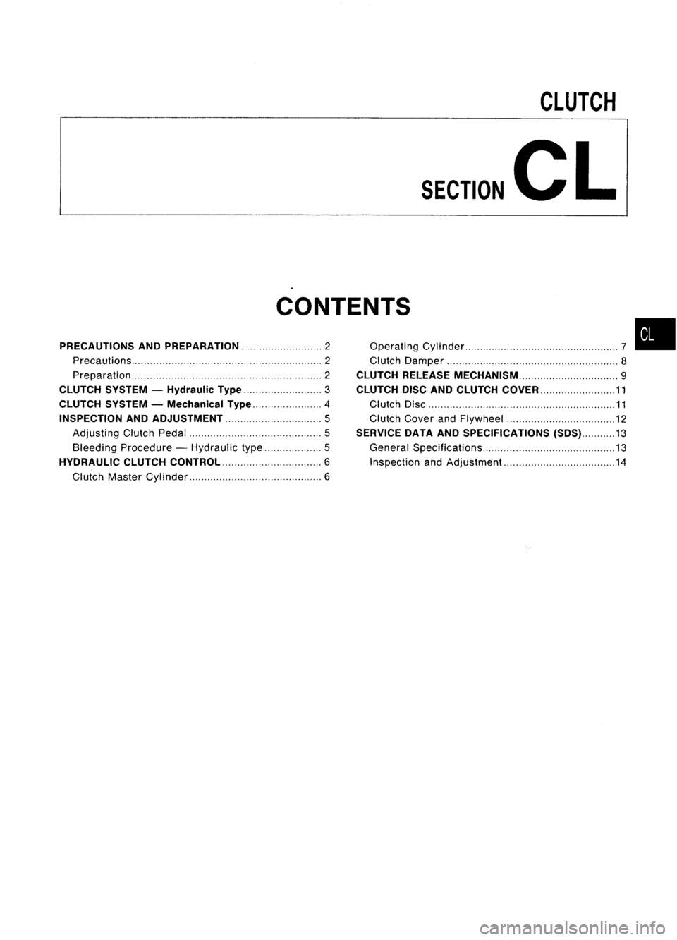
CLUTCH
SECTION
CL
CONTENTS
PRECAUTIONS ANDPREPARATION 2
Precautions 2
Preparation 2
CLUTCH SYSTEM-Hydraulic Type
3
CLUTCH SYSTEM-Mechanical Type 4
INSPECTION ANDADJUSTMENT
5
Adjusting ClutchPedal 5
Bleeding Procedure -Hydraulic type 5
HYDRAULIC CLUTCHCONTROL.. 6
Clutch Master Cylinder 6Operating
Cylinder 7
Clutch Damper 8
CLUTCH RELEASE MECHANiSM 9
CLUTCH DISCANDCLUTCH COVER 11
Clutch Disc 11
Clutch CoverandFlywheel 12
SERVICE DATAANDSPECIFICATIONS (SDS)13
General Specifications 13
Inspection andAdjustment 14
•
Page 360 of 1701
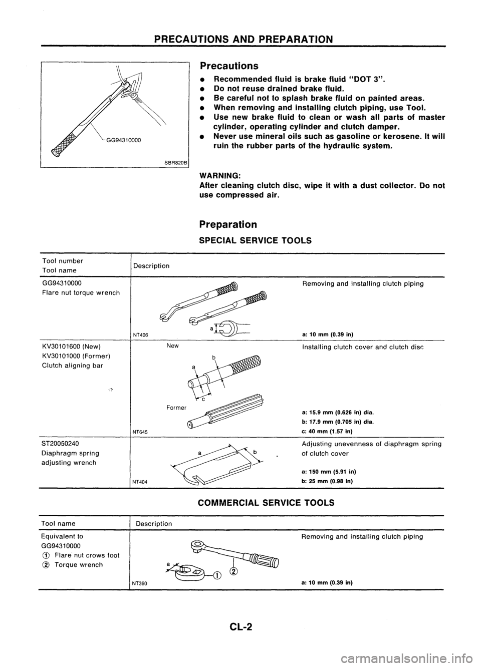
PRECAUTIONSANDPREPARATION
Precautions
• Recommended fluidisbrake fluid"DOT 3".
• Donot reuse drained brakefluid.
• Becareful nottosplash brakefluidonpainted areas.
• When removing andinstalling clutchpiping, useTool.
• Use new brake fluidtoclean orwash allparts ofmaster
cylinder, operating cylinderandclutch damper.
• Never usemineral oilssuch asgasoline orkerosene. Itwill
ruin therubber partsofthe hydraulic system.
Tool number
Tool name
SBR820B
WARNING:
After cleaning clutchdisc,wipe itwith adust collector. Donot
use compressed air.
Preparation
SPECIAL SERVICE TOOLS
Description
New
GG94310000
Flare nuttorque wrench
KV30101600 (New)
KV30101000 (Former)
Clutch aligning bar
ST20050240 Diaphragm spring
adjusting wrench
NT406
NT645
NT404
Removing
andinstalling clutchpiping
a:
10
mm
(0.39
in)
Installing clutchcoverandclutch disc:
a:
15.9
mm
(0.626 In)dia.
b: 17.9 mm(0.705 in)dia.
c: 40 mm (1.57 in)
Adjusting unevenness ofdiaphragm spring
of clutch cover
a: 150 mm (5.91 in)
b: 25
mm
(0.98
in)
Tool name
Description
COMMERCIAL
SERVICETOOLS
Equivalent to
GG9431 0000
CD
Flare nutcrows foot
@
Torque wrench
NT360
Removing
andinstalling clutchpiping
a: 10 mm (0.39 in)
CL-2