NISSAN ALMERA N15 1995 Service Manual
Manufacturer: NISSAN, Model Year: 1995, Model line: ALMERA N15, Model: NISSAN ALMERA N15 1995Pages: 1701, PDF Size: 82.27 MB
Page 551 of 1701
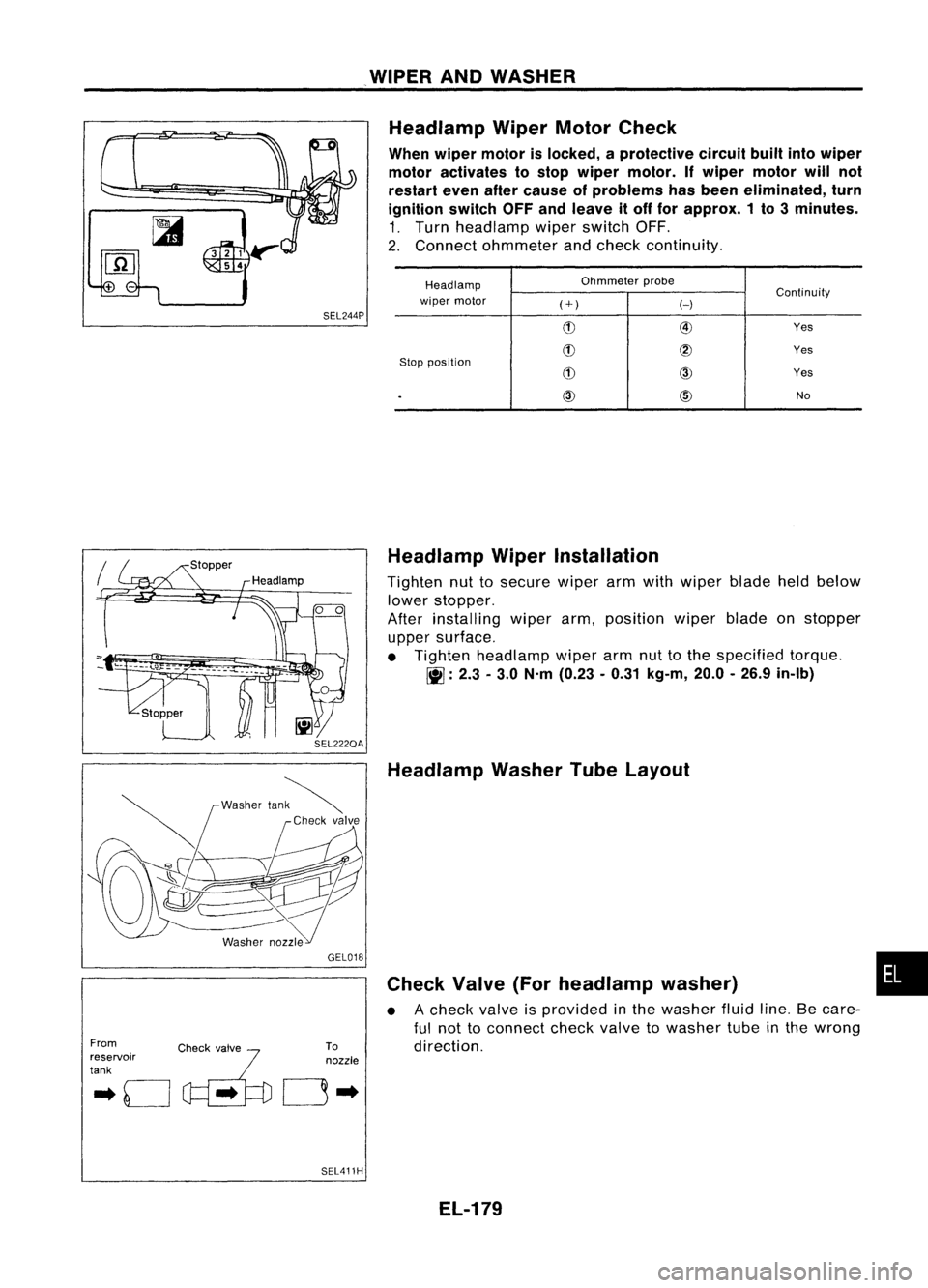
.WIPER ANDWASHER
SEL244P Headlamp
WiperMotorCheck
When wiper motor islocked, aprotective circuitbuiltintowiper
motor activates tostop wiper motor. Ifwiper motor willnot
restart evenaftercause ofproblems hasbeen eliminated, turn
ignition switchOFFandleave itoff for approx. 1to 3minutes.
1. Turn headlamp wiperswitch OFF.
2. Connect ohmmeter andcheck continuity.
Headlamp Ohmmeter
probe
Continuity
wiper motor
(+)
H
(!) @
Yes
(!)
@
Yes
Stop position
(!)
CID
Yes
.
CID
@)
No
From
.. 0
c~'..
~'fo
reservoir
tank GEL018
To
nozzle
0"
SEL411H Headlamp
WiperInstallation
Tighten nuttosecure wiperarmwith wiper bladeheldbelow
lower stopper.
After installing wiperarm,position wiperbladeonstopper
upper surface.
• Tighten headlamp wiperarmnuttothe specified torque.
~ :2.3 -3.0 N'm (0.23 -0.31 kg-m, 20.0-26.9 in-Ib)
Headlamp WasherTubeLayout
Check Valve(Forheadlamp washer)
• Acheck valveisprovided inthe washer fluidline.Becare-
ful not toconnect checkvalvetowasher tubeinthe wrong
direction.
EL-179
•
Page 552 of 1701
![NISSAN ALMERA N15 1995 Service Manual POWERWINDOW
System Description
Power issupplied atall times
• from 25Afusible link(Letter
IT],
located inthe fusible linkand fuse box)
• tocircuit breaker terminal
CD
• through circuitbreak NISSAN ALMERA N15 1995 Service Manual POWERWINDOW
System Description
Power issupplied atall times
• from 25Afusible link(Letter
IT],
located inthe fusible linkand fuse box)
• tocircuit breaker terminal
CD
• through circuitbreak](/img/5/57349/w960_57349-551.png)
POWERWINDOW
System Description
Power issupplied atall times
• from 25Afusible link(Letter
IT],
located inthe fusible linkand fuse box)
• tocircuit breaker terminal
CD
• through circuitbreaker terminal @
• topower window relayterminal
CID.
With ignition switchinON orSTART position, powerissupplied
• through 7.5Afuse (No.l2I located inthe fuse block)
• topower window relayterminal
CD.
Ground issupplied topower window relayterminal @
• through bodygrounds
@,
@D
and@D.
The power window relayisenergized andpower issupplied
• through powerwindow relayterminal
• topower window mainswitch terminals
CD
and @,
• topassenger sidepower window sub-switch terminals
CID
and @,
• torear power window sub-switch LHterminal @
>
• torear power window sub-switch RHterminal @.
MANUAL OPERATION
Driver's door
Ground issupplied
• tofront power window mainswitch terminals
CID
and @
• through bodygrounds
@,
@Dand
@!D.
WINDOW UP
When adriver sideswitch inthe power window mainswitch ispressed inthe upposition,
power issupplied
• todriver sidepower window regulator terminal@
• through powerwindow mainswitch terminal
em.
Ground issupplied
• todriver sidepower window regulator terminal
CD
• through powerwindow mainswitch terminal
cID.
Then, themotor raises thewindow untiltheswitch isreleased.
WINDOW DOWN
When adriver sideswitch inthe power window mainswitch ispressed inthe down position,
power issupplied
• todriver sidepower window regulator terminal
('t'
• through powerwindow mainswitch terminal
cID.
Ground issupplied
• todriver sidepower window regulator terminal~)
• through powerwindow mainswitch terminal
em.
Then, themotor lowers thewindow untiltheswitch isreleas.ed.
Except dr'ver's door
Ground issupplied
• topower window mainswitch terminal
CID
• through bodygrounds
@,
@Dand@D.
PASSENGER'S DOOR
NOTE:
Figures inparentheses ()refer toterminal Nos.arranged inorder whentheUPorDOWN section of
power window switchispressed.
Operation bymain switch
Power issupplied
• through powerwindow mainswitch
(CID,
@)
• topassenger sidepower window sub-switch (@,
CID).
El-180
Page 553 of 1701
POWERWINDOW
System Description (Cont'd)
The subsequent operationsarethesame asthose outlined under"Operation bysub-switches".
Operation bysub-switches
Power issupplied
• through passenger sidepower window sub-switch (@,
CD)
• topassenger sidepower window regulator
(@,
CD).
Ground issupplied
• topassenger sidepower window regulator
(CD,
@)
• through passenger sidepower window sub-switch
(CD,
@)
• topassenger sidepower window sub-switch
(CID,
@)
• through powerwindow mainswitch (@,
@)).
Then, themotor raises orlowers thewindow untiltheswitch isreleased.
REAR DOOR LH
NOTE:
Figures inparentheses ()refer toterminal Nos.arranged inorder whentheUPorDOWN section of
power window switchispressed.
Operation bymain switch
Power issupplied
• through powerwindow mainswitch (@,@)
• torear power window sub-switch LH(@,
CID).
The subsequent operationsarethesame asthose outlined under"Operation bysub-switches".
Operation bysub-switches
Power issupplied
• through rearpower window sub-switch LH(@,
CD)
• torear power window regulator LH(@,
CD).
Ground issupplied
• torear power window regulator LH
(CD,
@)
• through rearpower window sub-switch LH
(CD,
@)
• torear power window sub-switch LH
(CID,
@)
• through powerwindow mainswitch LH(@, @).
Then, themotor raises orlowers thewindow untiltheswitch isreleased.
REAR DOOR RH
NOTE:
Figures inparentheses ()refer toterminal Nos.arranged inorder whentheUPorDOWN section of
power window switchispressed.
Operation bymain switch
Power issupplied
• through powerwindow mainswitch
(@J,
@)
• torear power window sub-switch RH(@,
CID).
The subsequent operationsarethesame asthose outlined under"Operation bysub-switches".
Operation bysub-switches
Power issupplied
• through rearpower window sub-switch RH(@,
CD)
• torear power window regulator RH(@,
CD).
Ground issupplied
• torear power window regulator RH
(CD,
@) •
• through rearpower window sub-switch RH
(CD,
@)
• torear power window sub-switch RH
(CID,
@)
• through powerwindow mainswitch (@,@)
Then, themotor raises orlowers thewindow untiltheswitch isreleased.
AUTO OPERATION
The power window AUTOfeature enables thedriver toopen orclose thedriver's windowwithouthold-
ing the window switchinthe respective position.
When theAUTO switch inthe main switch ispressed andreleased, thedriver's windowwilltravel to
the fully open orclosed position.
EL-181
Page 554 of 1701
POWERWINDOW
System Description (Cont'd)
POWER WINDOW LOCK
The power window lockisdesigned tolock-out windowoperation toall windows exceptthedriver's door
window.
When thelock switch ispressed tolock position, groundofthe passenger sideswitch, rearRHswitch
and rear LHswitch inthe power window mainswitch isdisconnected. Thisprevents thepower window
motors fromoperating.
EL-182
Page 555 of 1701
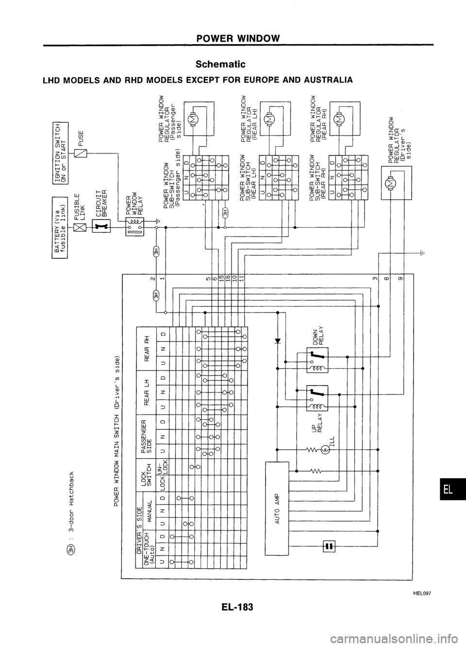
POWERWINDOW
Schematic
LHD MODELS ANDRHOMODELS EXCEPTFOREUROPE ANDAUSTRALIA
•
~
o
~
o
~
o
0
L
~
0
~
0
~
Z([W
Z([_
Z([_
HOOJ HOI
HOI
~I-C ~1--1~I-([
~
.---
<{W_
<{<{
([-1 UlOJ ([-1([
([-1([ 0
I W:::JUlDW::J
U Z([Ul
I- W
~r.9
ro.""
~r.9W
~r.9W
HO-
H (J)
OW[LUl OW([
OW([
::J [L([-
[L([-
[L([- ~I-L
~I- LL
III
([-1>OJ
<{
-0
-
W:::J,""D
ZI- OJ
~r.9L'''''
O(J) D
10
fa
~
101-10
~
10
fa
OWOUl
H
.,..,
0
0
0 0
[L([-
I-L
~
Ul OI
OI
0
HO 0ZU_
ZU_
v
'-'
Z OIL
'01-
HI-I
-10
HI-I
~>-
~
r.9Z
ZUOJ
Z ~H...J
Z ~H(I
Z
HO HI-
OJ
10
fa
~
01--0
~
1'-'
rv
'---
~HC
([(J)([
([(J)(I
~W WI<{
WI<{
1-([ ([(J)Ol
::J ~(J)W
:::J ~(J)W
::J
01.:::
['-'
-
W
HW
~
WIOl
0>-
O::J([
-10
O:::J([
-1 :::J:><: ([0>-
~CD
ro
[L(J)-
[L(J)-
CD
U<{ WO<{
O:::JO-
-
H:><:
(IW ~Z...J
[L(J)-
.
:>t.
OHW
roc
(J)Z
H([
I
.r-t.ri
:::JH
UCD [L~a:
f'1
> ......
LL-1
r=l
~II
>-OJ
~.~
(I ......
=
r
W.o
1-.""
I-Ol
@
<{:J
I-
CD'+-
1
-
ru
.....
lD(o~
(DO
.....
(T)
co
m
..........
"'"
,
I
>-
0
Z<{
~-1
I
,
ow
(I
0([
(I Z
~
-
.-----
<{
~
-f-t......
W
W
(I
D ::J
v_
V
.....
000
Ol
Ul
0
I
L ...J
~
OJ (IZ
1_1-
o-f-L...
> IV
.....
<{
L W
9
([
~
::J
'vv
I >-
U (I
0
10
<{
I-
10
-1
W O-W
H
r.9
~
Z ::J([
(J) WZ
'V
...J
Z (J)W
...........
~
(J)O
H <{I-<
<{ [L(J)
::J
10/0
IV'
~
::E
~
::.:::
0
I
IU
Ie
0
UZO
-
:>t.
Z::':::1-::J...J
W
I-
::.:::
ro
~
O~
U
D
-1(J)
0
.c
([
...J
w
W
+'
~
0
10-10
0-
ro
0
::E
I [L-1
<{
::J
Z 0
0
0
Z
l-
I-<
::E
:::J
D ::J
fa
<{
I (J)
(Y]
(II
0
.,
WU
'v
1'-'
>::J
I.':l
@
I-<
0_
(I 1-0
Z
~
o
I+'
W:J
Z
HEL097
EL-183
Page 556 of 1701
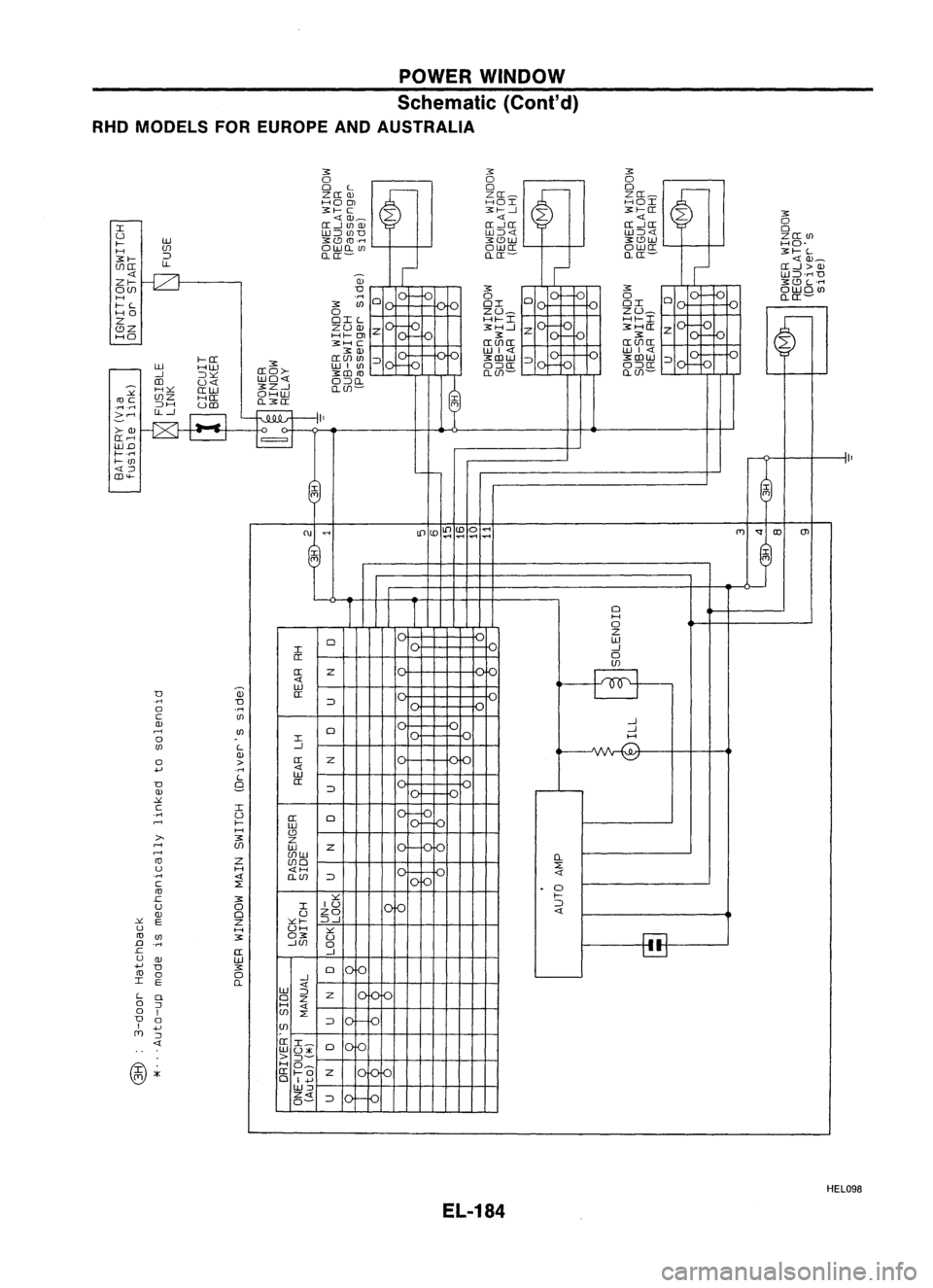
POWERWINDOW
Schematic (Cont'd)
RHO MODELS FOREUROPE ANDAUSTRALIA
3:
o
3:
o
0
L
~
0
~
0
~
ZO:OJ
ZO:~ZO:_
HO
OJ
HOI
HOI
3:f-- C 3:f---.J3:f--0:
3:
r--
0:-10: 0
I
0
U W:JUJD
W:J
W 3:
CD
CO.n
3:CDW 3:CDW
f--
(f) OWQUJ OWO:OWO: HO-
H :J QO:-
QO:-QIT- 3:f--L
3:f--
LL
III
O:-1>OJ
--[Z}
-
W:J'M
D
Zf-- OJ
3:CDL'M
O(f) D
Jo
I~
3:
01-
3:
10-10_
oWOUJ
H 'M
0
1'U
1_
.r.
0
0
0
0
QO:-
I--L 3:If)
OI OI
HO 0ZU_
ZU_
'J
Z OIL
f-
HI--I
zio
-10
HI--I
01-D
~
CDZ
~2~
Z 3:H-1
3:HO:
Z
HO
IVIV
3:
01-
3:
10-10
'--
3:H
C 0:(f)0: 0:(f)0:
3: OJ WI
:J 3:1I1W
:Jlo
-1-0
3:1I1W
:J
,01- D
-
W
HW 3:
WIUJ
f--.
O:JO: O:JO:
-.J :J~ 0:0>-
3:1I1CO Q(f)-
Q(f)-
III
U
-
H~
O:W 3:Z-1
Q(f)-
C>t.
(f)Z HO: OHW
coe
Q3:O:
I
.rl
.rl
:JH
UIIl
'"
.:::....-<
~EJ ~
II
>-OJ
0:...-<
=
WD
I-- 'M
I--If)
~
-f--.
CD .....
(ili
T
~I "
If)lO~
lOa"
(T)
'f
llJ
OJ
"
...,
...,
@
~
I
I
0
H
0
-
Z
0
W
I -1
0: 0
(f)
0: Z
~
ill
W
D
a:
.rl
D :J
0
'M
I'J
C UJ
-1
OJ
.--<
UJ
0
--
-1
0
I
'J
~
H
(f)
L-.J
.•r'\
OJ 0:
Z
'V
0
>
+'
'M
I-I-
D
9
a:
OJ :J
C>t.
C I
101-
.rl
U
IT
0
Ie
...-<
I--
W
10
H
CD
>-
3:
Z
,-
I-
.--<
(f)
W
Z
.--<
(f)W
I'J
0-
co
Z(f)O
::E
u
H
I-
.rl
10
C
::E
.
0
co
.c
3:
~
I--
u
0IIU
10D
:J
OJ
0
UZO
y.
E
Z
~I--:J-1
u
HUH
~
r:-:l
co
(f)
3:03:
U
.0
.rl
-.J(f)
0
.c
IT-1
~
u
OJ W
+'
D 3:
0
10
co
0
0
-.J
I
E
0-
:J
Z
!ofo
Q
0
Z
0
:J H
0
1
(f)
::E
D
0
:J
10 D
I
+'
(f)
(T)
:J
556*
0
10
..
>
:J-
@.
HO_
10Dfo
(T) '"
0:
I--
0
Z
o
I......
W:J
Z
D
0-
HEL098
EL-184
Page 557 of 1701
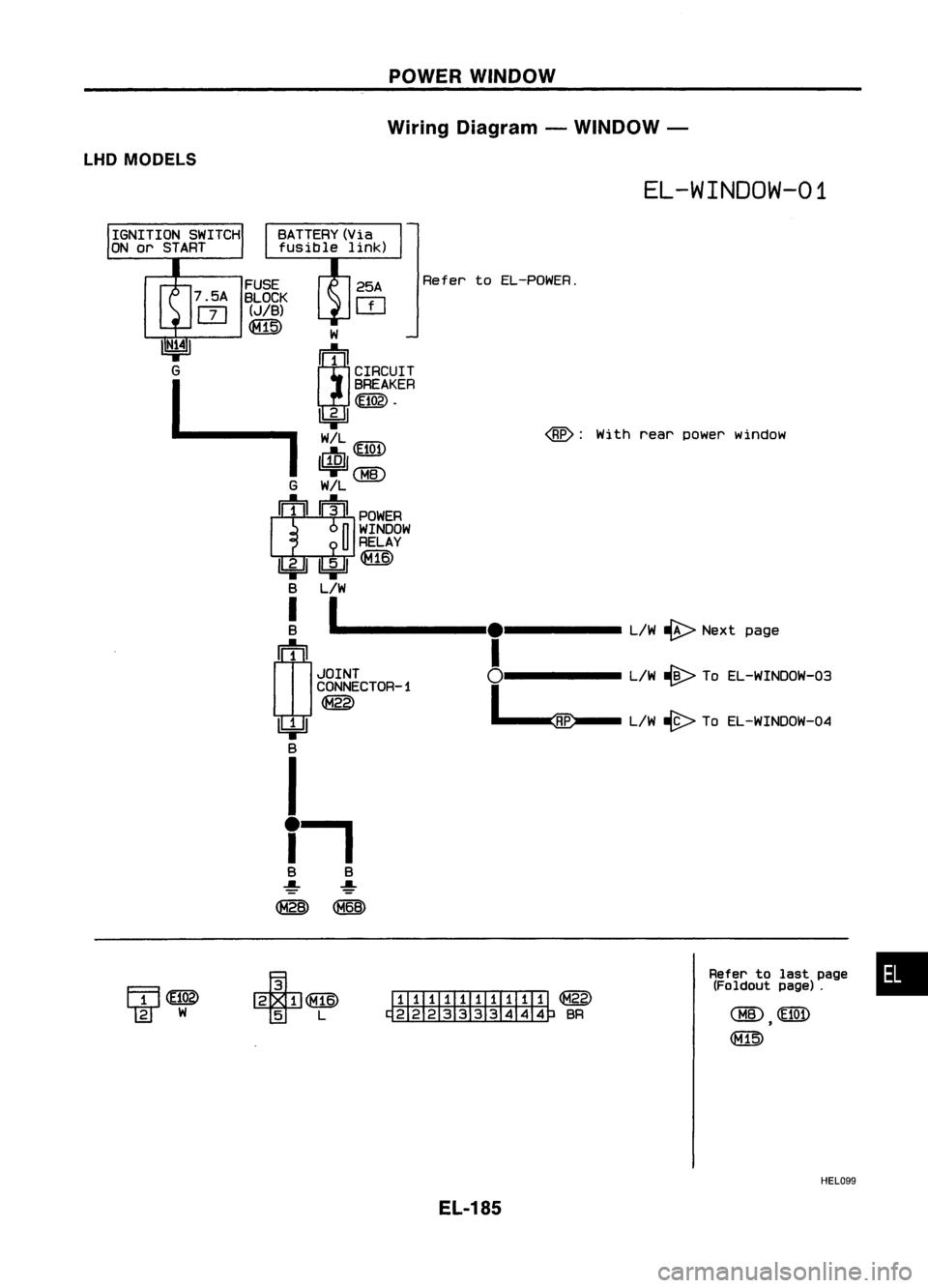
POWERWINDOW
Wiring Diagram -WINDOW -
LHD MODELS
EL-WINDOW-01
Withrearpower window
Refer
toEL-POWER.
W
~1
CIRCUIT
BREAKER
~.
Ibj:JJ
~~
II..!QJI
=rQ1ID
G W!L
II!I ~II
POWER
n
WINDOW
U
RELAY
1biJl1bjdI~
B L/W
!
1 -----
L/W~ Next page
crJ
1
I
IL1JI ~J~;JCTOR-1 °1-----L/W~ ToEL-WINDOW-03
=r -,--::~ ..-
L/W -@>TOEL-WINDOW-04
B
I
i.
B B
~ ~
~ ~
FUSE
BLOCK
(JIB)
~
I:IIITill1IIill
@
~BR
Refer
tolast page •
(Foldout page).
HEL099
EL-185
Page 558 of 1701
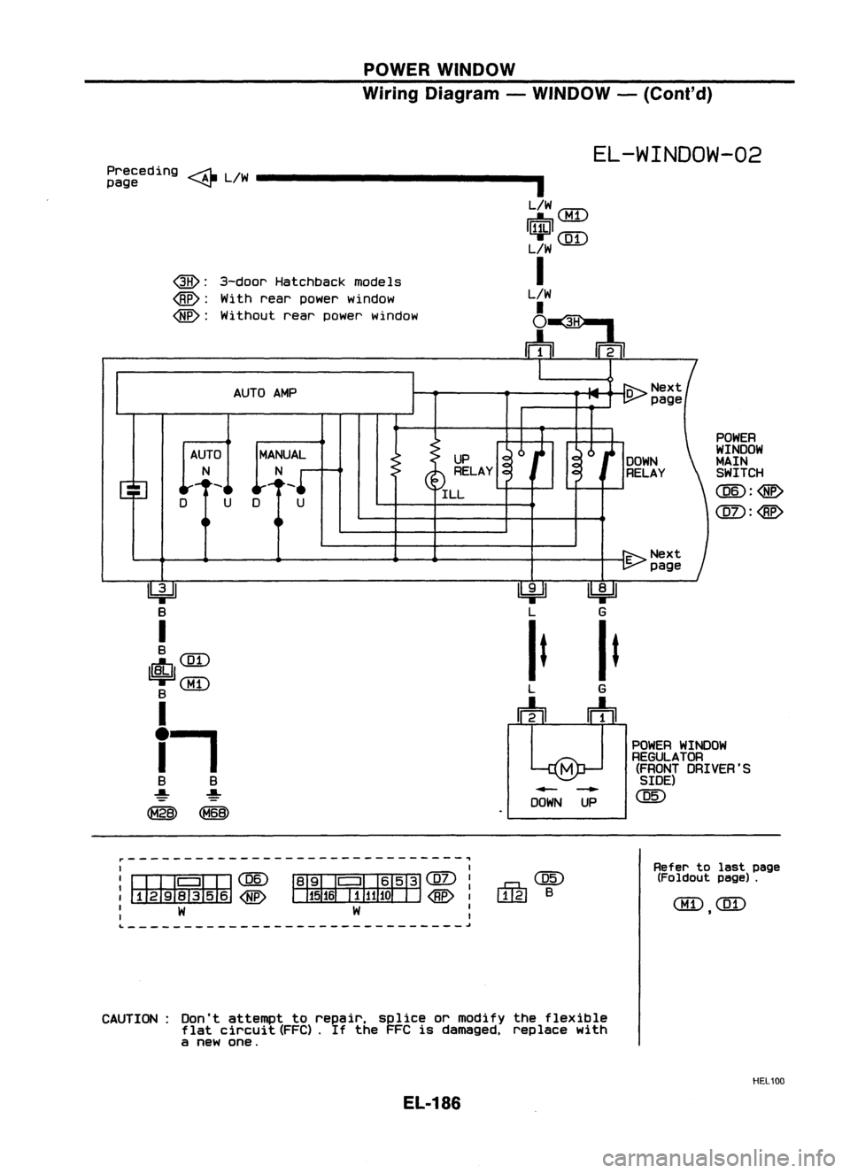
POWERWINDOW
Wiring Diagram -WINDOW -(Cont'd)
EL-WINDOW-02
POWER
WINDOW
MAIN SWITCH
CQID:@
@D:
UP
RELAY
ILL
MANUAL
N
D U
AUTO
AMP
AUTO
N
QB):
3-door Hatchback models
@:
With rear power window
Without rearpower window
~
Ibi=Jl
~
B
L
G
I
ItIt
B
I$I
CQD
QID
LG
B
m
rrh
I
i-,
POWER
WINDOW
REGULATOR (FRONT DRIVER'S
B B
SIDE)
~ ~
--
@)
~ ~
DOWN
UP
Preceding
~L!W _
page ~
I
'::'QID
I~I
rr=rr'I
LlW&1..J
I
L/W
~~
rr+n
m
~------------------------------,
I I
I
CIJ:JQITJ
@)
~@D
I
:~
~
: W W:
...g.,@
W£J B
Refer
tolast page
(Foldout page).
QID
CQD
,
L ~
CAUTION: Don'tattempt torepair, spliceormodify theflexible
flat circuit (FFC).
If
the FFC isdamaged, replacewith
a new one.
HEL100
EL-186
Page 559 of 1701
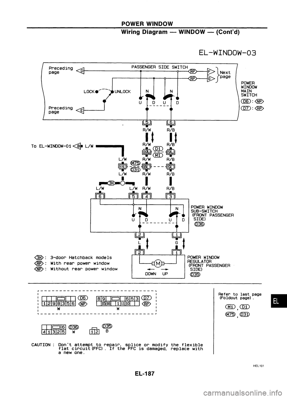
POWERWINDOW
Wiring Diagram -WINDOW -(Cont'd)
EL-WINDOW-03
POWER
WINDOW
MAIN
SWITCH
CQID:
CQD:@
N
N
LOCK .....-- UNLOCK
o
Preceding
page
Preceding
page
~~
R/W RIB
To EL-WINDOW-01 <@-L/W
----I
R~JR~J
1$~t~{fi~1
L/W
@)
R/W RIB
IriJ~ 4J~1)
~1iJ~ -- -
~tJl
L/W R/W RIB
~~~ II
L/W L/WR/W RIB
m mm m
POWERWINDOW
SUB-SWITCH (FRONT PASSENGER
SIDE)
@£)
L
J
I
~(gl)1
~
W
I
I
•
Refer
tolast page
(Foldout page).
4=U
G
t
~
POWER WINDOW
REGULATOR (FRONT PASSENGER
- - SIDE)
DOWN UP ~
I
I~CQID
:~
: W
QH):
3-door Hatchback models
@:
Withrear power window
Without rearpower Window
[I]QID~
~W
~@
l..!@
B
CAUTION: Don'tattempt torepair. spliceormodify theflexible
flat circuit (FFC).If the FFC isdamaged. replacewith
a new one.
HEL101
EL-187
Page 560 of 1701
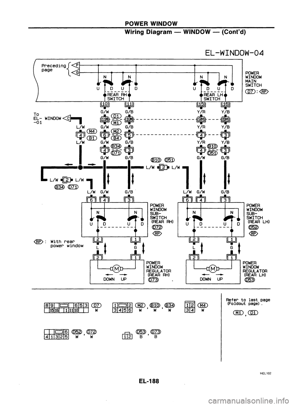
POWERWINDOW
Wiring Diagram -WINDOW -
(Co nt'd)
EL-WINDOW-04 POWER
WINDOW
MAIN SWITCH
CQZ):
<8£>
precedin9{
F
page
UDU
------
REAR RH
SWITCH
~ U¥Jl ~~
To G/WGIS Y/RY/S
EL -WINDOW
<-0~~
-It~ ---- -- ------ -----It~ ---
-1$1
-01 ~
I
CHI)
L/W
GIW GIS Y/RY/S
m
GID I~~
<-M5~~~~ ---- - -------- -- -
~r!l~ ---
~11l1
....... (]I)
'"T~ '"T .......'"T
L/W GIW~ GIS Y/R~ Y/S
I
m-~-ffi m-~O-ffi
....... @
'"T .......~ '"T
L
L~;: ~
GI; Gli-
L/~~/W
1
GI; Git
L/W
GIW GIS.
L/W
GIW GIS
rmm m mmm
POWER POWER
N WINDOW
N WINDOW
SUB- SUB-
SWITCH SWITCH
(REAR RH)
(REARLH)
@g)
@
<8£>
@
<8£> :
With
rear
power window
POWER POWER
WINDOW WINDOW
REGULATOR REGULATOR
- -
(REAR
RH)
-
-
(REAR
LH)
DOWN UP
qm)
DOWN
UP
@
~@)
~W
~lllfij@
~~
~@
3456 W'W 'W ~W
Refer
tolast page
(Foldout page).
aID
CQD
,
CIJQIID
@
@g)
~ W'W
rR,@~
l.!.LEJ
B'B
HEL102
EL-188