NISSAN ALMERA N15 1995 Service Manual
Manufacturer: NISSAN, Model Year: 1995, Model line: ALMERA N15, Model: NISSAN ALMERA N15 1995Pages: 1701, PDF Size: 82.27 MB
Page 521 of 1701

EL-WARN-11
•
PARKING
SRAKE
SWITCH
~
Refer tolast page
(Foldout page).
(Me) (E1Ot)
(fill)
,--
RELEASED
<C>:
LHDmode 1")
WARNINGLAMPSANDBUZZER
Warning Lamps/Wiring Diagram-WARN -
(Cont'd)
EL-WARN-11
•
PARKING
SRAKE
SWITCH
~
Refer tolast page
(Foldout page).
(Me) (E1Ot)
(fill)
,--
RELEASED
LHDmode 1s
@:
RHOmodels
<@):
Except
*5 ...
20([) 1
.
COMBINATION
METER
~
BRAKE
NR
H
LOW
~
Y/B
.... I
o
+
~Y:: NR
*~Y/B---~O
JUNCTION BOXNO.2
I
I
*.5
I
(JOINT CONNECTORS)
Y/B~:
~ JOINT CONNECTOR-5
O-
~@):@
.... ~ ~@)
Y/B
I
-----D-O
ICiJI@
I$I(~:;
~ Y/BY/S
I~I ~
I$I
CMID
I
T--
.,... ~ m ----.~
I
Y/B Y/S
m
ctJ
Y/B
BRAKE BRAKE ~
FLUID FLUID II1II
~~~~EH '--~~~~EH
n
~ HIGH ~
~ Ef1"
I
'~O
l!-
III, ~
ffi
(E51)
Preceding
page
,--
HIGH
~@)
~OR m@
m
GY
t1\@
tgj
GY
R
(B14)
W
B
HEL081
EL-149
Page 522 of 1701

EL-WARN-12
<D:
LHDmodels
<ID:
RHOmodels
~: 5-door Hatchback and
Sedan models
*6 ...
<D
21
<ID
4
,
COMBINA
nON
DOOR ME")
WARNINGLAMPSANDBUZZER
Warning Lamps/Wiring Diagram-WARN -
(Coni' d)
EL-WARN-12
~: 5-door Hatchback and
Sedan models
*6 ...
,
COMBINA
nON
DOOR METER
~
11
2•8
1
R/W
rn
*~1
JUNCTION 80XNO.2
(JOINT CONNECTORS)
~:
JOINT CONNECTORS-1
'*.61
@:
~I
R/W R/W
IUC'\
wt;,CMID
m~
'iJ@
~@)
R/W R/W
*~
I
.----- _1IIIIII(~)II_.1
I
R/W
u=tn
Preceding
I
page
OPENOPEN
OPENOPEN
.....
_-
.....
_-
....._- .....
_-
CLOSED CLOSED
CLOSED CLOSED
FRONT FRONT
REAR REAR
DOOR
-
DOOR
-
DOOR
-
DOOR
-
SWITCH SWITCH
SWITCH SWITCH
DRIVER'S PASSENGERLH RH
SIDE SIDE
~:~
@):~
@)
~
CillIITillTIIil ~
~BR
Refer
tolast page
(Foldout page).
~
~~@)
5 6
jelvo
1112W
r1T2l@)
lID""
B
~@)@)
UJ
BR'SR 'SR
HEL198
EL-150
Page 523 of 1701

More than10-20
NO
Engine
start
(0.10-0.20, 0.1-0.2, 1.4-2.8)
Less than10-20
YES
Engine
stop")
Ohmmeter- + WARNING
LAMPSANDBUZZER
Oil Pressure SwitchCheck
Oil pressure
Continuity
kPa (bar, kg/cm
2,
psi)
More than10-20
NO
Engine
start
(0.10-0.20, 0.1-0.2, 1.4-2.8)
Less than10-20
YES
Engine
stop
(0.10-0.20, 0.1-0.2, 1.4-2.8)
SEL748K
Test lamp 3.4WON
\ ,I
"
/
Ballery
Test lamp 3.4W OFF
~0
CD
Ballery
Gasoline MEL623D
SEL901F
Check
thecontinuity betweentheterminals ofoil pressure
switch andbody ground.
Fuel Warning LampSensor Check
• Itwill take ashort timeforthe bulb tolight.
Diode Check
• Check continuity usinganohmmeter.
• Diode isfunctioning properlyiftest results areasshown in
the figure atleft.
NOTE:
Specification mayvary depending onthe type oftester. Before
performing thisinspection, besure torefer tothe instruction
manual forthe tester tobe used.
• Diodes forwarning lampsarebuilt intothecombination
meter printed circuit.
Refer to"Combination Meter"(EL-127).
Warning BuzzerUnit
• Seat beltwarning lampiscontrolled bythe warning buzzer
unit.
Refer to"Warning Buzzer"(EL-152).
EL-151
•
Page 524 of 1701

• through 7.5Afuse (No.
[f")
WARNINGLAMPSANDBUZZER
Warning Buzzer/System Description
The warning buzzeriscontrolled bythe warning buzzerunit.
Power issupplied atall times
(RHD models exceptforEurope)
• through 7.5Afuse (No.
[fA],
located inthe fuse block)
• tokey switch terminal
CD.
Power issupplied atall times
(LHD models withoutdaytime lightsystem)
• through 75Afusible link(letter
[.9J,
located inthe fusible linkand fuse box).
• tolighting switchterminal
@.
(LHD models withdaytime lightsystem andRHD models)
• through 10Afuse (No.
~J,
located inthe fuse block)
• tolighting switchterminal
@.
Power issupplied atall times
(Except forAustralia)
• through 7.5Afuse (No.~,located inthe fusible linkand fuse box)
• torear foglamp switch terminal
CD.
With theignition switchinthe ONorSTART position, powerissupplied
• through 7.5Afuse (No.
11J,
located inthe fuse block)
• towarning buzzerunitterminal
@
(LHD models exceptforAustralia) or
CD
(For Australia).
When driver's doorisopened, groundissupplied
• through bodygrounds
@
and
@
• todriver's sidedoor switch terminal
@
• through driver'ssidedoor switch terminal
G)
• towarning buzzerunitterminal
@
(Except forAustralia) or
(J)
(For Australia).
With power andground supplied, thewarning buzzerwillsound.
Ignition keywarning buzzer(RHOmodels exceptforEurope)
With thekey inthe ignition switchinthe OFF position, andthedriver's dooropen, thewarning buzzer
will sound. Abattery positive voltageissupplied
• from keyswitch terminal
CID
• towarning buzzerunitterminal
CID
(Except forAustralia) or
@)
(For Australia).
Ground issupplied
• from driver sidedoor switch terminal
G)
• towarning buzzerunitterminal
@
(Except forAustralia) or
(J)
(For Australia).
Driver sidedoor switch terminal
@
isgrounded throughbodygrounds
@
and
@.
Light warning buzzer
With ignition switchOFF,driver's dooropen, andlighting switchin1ST or2ND position, warningbuzzer
will sound. Abattery positive voltageissupplied
(LHD models withoutdaytime lightsystem)
• from lighting switchterminal
@
• through 10Afuse (No.
@ID,
located inthe fusible linkand. fuse box)
• towarning buzzerunitterminal
@>.
(LHD models withdaytime lightsystem)
• from lighting switchterminal
@
• todaytime lightunitterminal
@
• through daytime lightunitterminal
@>
• towarning buzzerunitterminal
@>
(RHD models)
• from lighting switchterminal
@
• towarning buzzerunitterminal
@>
(Except forAustralia) or
@
(For Australia).
Ground issupplied
• from driver sidedoor switch terminal
G)
• towarning buzzerunitterminal
@
(Except forAustralia) or
(J)
(For Australia).
Driver sidedoor switch terminal
@
isgrounded throughbodygrounds
(!ill
and
@.
Rear foglamp switch warning buzzer(ForEurope models)
With ignition switchOFF,driver's dooropen, andrear foglamp switch ON,warning buzzerwillsound.
A battery positive voltageissupplied
EL-152
Page 525 of 1701

• from rearfoglamp switch terminal @
• towarning buzzerunitterminal @.
Ground issupplied
• from driver sidedoor switch termin")
WARNINGLAMPSANDBUZZER
Warning Buzzer/System Description(Cont'd)
• from rearfoglamp switch terminal @
• towarning buzzerunitterminal @.
Ground issupplied
• from driver sidedoor switch terminal
(1)
• towarning buzzerunitterminal @.
Driver sidedoor switch terminal
CID
isgrounded throughbodygrounds
(ill)
and
@.
EL-153
•
Page 526 of 1701
![NISSAN ALMERA N15 1995 Service Manual WARNINGLAMPSANDBUZZER
Warning Buzzer/Wiring Diagram-BUZZER -
LHD MODELS
EL-BUZZER-01
DOOR
SWITCH
DRIVER'S
SIDE
(]ID
OPEN
Refer
to
EL-POWER.
CLOSED
IJ:i=n
B
•
f.
B B
~ ~
@ll)@
FUSE
BL](/img/5/57349/w960_57349-525.png "NISSAN ALMERA N15 1995 Service Manual WARNINGLAMPSANDBUZZER
Warning Buzzer/Wiring Diagram-BUZZER -
LHD MODELS
EL-BUZZER-01
DOOR
SWITCH
DRIVER'S
SIDE
(]ID
OPEN
Refer
to
EL-POWER.
CLOSED
IJ:i=n
B
•
f.
B B
~ ~
@ll)@
FUSE
BL")
WARNINGLAMPSANDBUZZER
Warning Buzzer/Wiring Diagram-BUZZER -
LHD MODELS
EL-BUZZER-01
DOOR
SWITCH
DRIVER'S
SIDE
(]ID
OPEN
Refer
to
EL-POWER.
CLOSED
IJ:i=n
B
•
f.
B B
~ ~
@ll)@
FUSE
BLOCK
(JIB)
~
m
IN~41
@:
Withdaytime lightsystem
G1@:WithoutdaytimelightsYstem
*1".@B/R @W
,
G *2...
@
RIL @W/R
•
~ *3".@R/B @R/Y
1I1DI •
IGN WARNING
SW BUZZER
RR FOG DOORUNIT
SW SW(DR)
@
lbjdJ ~
PU/R R
[ttl ']'t4IJUNCTION
BOX NO.2
(JOINT
CONNECTORS)
~------1I~41
PU/R
t
~@)
m
REAR
[jJ
(]V
IND FOG R
LAMP ~
SWITCH II1II
~
OFF
7.5A
1431
B/R
rm
TAIL/L FUSE
I!JjJJ
*2
I
O~ DL W/R
[iJt~:1
R/Y
t
I_-.I~o
tt
RIB
Ii1'on
TAILIL
OUTPUT
RIL
will
TAILIL
SW
\bj::tl
B
rn~
I
JOINT
CONNECTOR-3
I
lU ....,
DAYTIME
=jF
I
LIGHT B
UNIT BB
I..-.--
---J~~
I
BATTERY
I
•
~-17-5A-~'
10.
m
1361
W B/R P
!
I.-",
1$1
~~1)
*1 P
will
L
LIGHTING
SWITCH
~
~~
~BR
IIITIillIIITIIT
@
~BR
~~@)
56j8191OU12 W
r1TmCW
TIT'
B
Refer
tolast page
(Foldout page).
(BID ~
•
~ (106)
•
~~
~GY
HEL083
EL-154
Page 527 of 1701

RHO MODELS EXCEPTFORAUSTRALIA
DOOR
SWITCH
DRIVER'S
SIDE
em:>
Refer
to
EL-POWER.
WARNING
BUZZER
UNIT
(M33)
OPEN
FUSE")
WARNINGLAMPSANDBUZZER
Warning Buzzer/Wiring Diagram-BUZZER -
(Cont'd)
RHO MODELS EXCEPTFORAUSTRALIA
DOOR
SWITCH
DRIVER'S
SIDE
em:>
Refer
to
EL-POWER.
WARNING
BUZZER
UNIT
(M33)
OPEN
FUSE
BLOCK
(JIB)
(E106)
For Europe
Except forEurope
DOOR
SW (DR)
~
R
I
R
~@
1C}l1C@
R
I
R
m
CLOSED
l!:j:!J
B
I
i.
8 8
-!-
-!-
(811) (832)
EL-BUZZER-02
KEY
SW@
IbjdJ
BR/Y
t
KEY-IN
IN SWITCH
@:@
RR
FOG
SW@
IbjdJ
PU/R
It
~
BR/Y
I
BR/Y ~ (E10t)
I~ICBID
BR/Y
LIGHTING
SWITCH
(E107)
I
PU/R
m
REAR
IND FOG
LAMP SWITCH
~: @
OUT
~ B
(1)
1
JOINT
CONNECTOR-4
(M59)
U
1 ,.
n
B BB B
1
t..J
1
~
OFF
I
BATTERY
I
•
~.7.1 ~.~A.I-_.~
t:1
P B/R
I
frill
P
~llli:D
I~ICMID
P
Refertolast page •
(Foldout page).
CHID
(E101)
,
,
IIfIIIITIillTII
@~ ~~
(E115)
rffll
@)
~P ~BR
ITJ:g]
W
m
B
~:EL084
EL-155
Page 528 of 1701

FOR AUSTRALIA
GND
~ B
rn
1
JOINT
CONNECTOR-4
~
U
'I
n
8
tit.Ji
@<MW ~
Refer
to
EL-POWER.
WARNING
BUZZER
UNIT")
WARNINGLAMPSANDBUZZER
Warning Buzzer/Wiring Diagram-BUZZER -
(ConI' d)
FOR AUSTRALIA
GND
~ B
rn
1
JOINT
CONNECTOR-4
~
U
'I
n
8
tit.Ji
@
to
EL-POWER.
WARNING
BUZZER
UNIT
@
FUSE
BLOCK
(JIB)
~
t
i-,
B B
-:!:- ~
([fi) ~
EL-BUZZER-03
KEY-IN
IN SWITCH
@
OUT
~
BR/Y
~ 101
~CBID
BR/Y
I
BR/Y G
m
ffi
KEY IGN
SW SW
DOOR SW
(DR)
~
R
Ii1=nCBID
~@)
R
m
DOOR
SWITCH
OPEN DRIVER'S
SIDE
CLOSED
@)
~
B
LIGHTING
SWITCH
m
-,
SB
RIG
rn
ffi
SEAT BELT LIGHT
WARN SW
I
BATTERY
I
I
~10A
L:J
1361
SiR
rrfnJ
To EL-WARN" SB
~@
~W
~
[I[g]
W
~@)
W
B
Refer
tolast page
'(Foldout page).
ITIillJIIIIII1T ~
~P
HEL085
EL-156
Page 529 of 1701
WARNINGLAMPSANDBUZZER
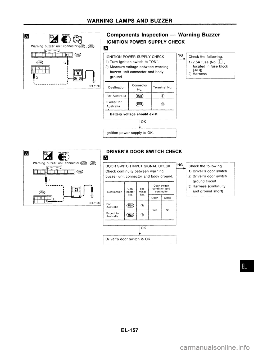
Components Inspection-Warning Buzzer
IGNITION POWERSUPPLY CHECK
m
~i3~
Warning buzzerunitconnector
@,~
II
IIIItflm
1
U
@
@
GI
[tlIffiJl
l~V
'G
I"'_
I '
, I":'"
~--------_
...
_--._,
SEL515U
IGNITION
POWERSUPPLY CHECK
1) Turn ignition switchto"ON".
2) Measure voltagebetween warning
buzzer unitconnector andbody
ground.
Destination Connector
TerminalNo.
No.
For Australia
@
(1)
Except for
@
@
Australia
Batlery voltage shouldexist.
OK
Ignition powersupply isOK.
NG
Check thefollowing.
1) 7.SA fuse(No.
II],
located infuse block
[JIB))
2) Harness
~ 15
Warning buzzerunitconnector
@,@
~~Ijjll II
II
@jj)
I
@jj)
-"'-----1
[rnlli
1
I~ __
~R __) -
._ITIJ1.B ~. SEL512UDRIVER'S
DOORSWITCH CHECK
m
DOOR SWITCH INPUTSIGNAL CHECK NG
Check thefollowing.
Check continuity betweenwarning
--..
1)Driver's doorswitch
buzzer unitconnector andbody ground. 2)
Driver's doorswitch
ground circuit
Door switch
3)Harness (continuity
Can- Ter- condition
and
Destination nectorminal continuity
and
ground short)
No No.
Open Close
For
@
(t)
Australia
YesNo
Except for
@
@)
Austraiia
1
0K
Driver's doorswitch isOK.
EL-157
•
Page 530 of 1701
![NISSAN ALMERA N15 1995 Service Manual
Checkthefollowing.
1) 10A fuse (No.
[lli),
and 75Afuse (No.
[!])
2) Lighting switch
3) Harness
NG
Lighting switch
Can- Ter- condition
and
Destination nectorminal voltage
[VI
No. No.
1stor
2nd O](/img/5/57349/w960_57349-529.png "NISSAN ALMERA N15 1995 Service Manual
Checkthefollowing.
1) 10A fuse (No.
[lli),
and 75Afuse (No.
[!])
2) Lighting switch
3) Harness
NG
Lighting switch
Can- Ter- condition
and
Destination nectorminal voltage
[VI
No. No.
1stor
2nd O")
Checkthefollowing.
1) 10A fuse (No.
[lli),
and 75Afuse (No.
[!])
2) Lighting switch
3) Harness
NG
Lighting switch
Can- Ter- condition
and
Destination nectorminal voltage
[VI
No. No.
1stor
2nd OFF
For
@
@
Australia
Approx.
0
12
Except for
@
@)
Australia
LIGHTING
SWITCHINPUTSIGNAL
CHECK
Measure voltagebetween warning
buzzer unitconnector andbody ground.
WARNING
LAMPSANDBUZZER
Components Inspection-Warning Buzzer
(Cont'd)
LIGHTING SWITCHCHECK
Fa
~i)
Warning buzzerunitconnector
@,@
II
III
IFfI1L
f
ill
@
RIGI
II
@ ~
1
144J,..!--!}~~~_ ..) ~
L::.
===::::..1.
SEL514U
OK
Lighting switchisOK.
IGNITION KEY-INSWITCH SIGNALCHECK-RHO
models exceptforEurope
Fa
Warning
buzzerunitconnector
@,@
II
II
I'Ff,l1
f
LLDJ
@
'BRN
I
@
i~
18
5~~~~~~'C) ~
SEL513U
KEY-IN
SWITCH INPUTSIGNAL CHECK
Measure voltagebetween warning
buzzer unitconnector andbody ground.
Ignition key
Can- Ter- condition
and
Destination nectorminal voltage
[VI
No. No
Inserted Re-
moved
For
@
CID
Australia
Approx
0
RHO models
12
except for
@
(9J
Australia
NG
Check thefollowing.
1) 7.5A fuse(No.
[W,
located infuse block
[JIB])
2) Ignition keyswitch
3) Harness
OK
Ignition keyswitch isOK.
EL-158