NISSAN ALMERA N15 1995 Service Manual
Manufacturer: NISSAN, Model Year: 1995, Model line: ALMERA N15, Model: NISSAN ALMERA N15 1995Pages: 1701, PDF Size: 82.27 MB
Page 531 of 1701
WARNINGLAMPSANDBUZZER
Components Inspection-Warning Buzzer
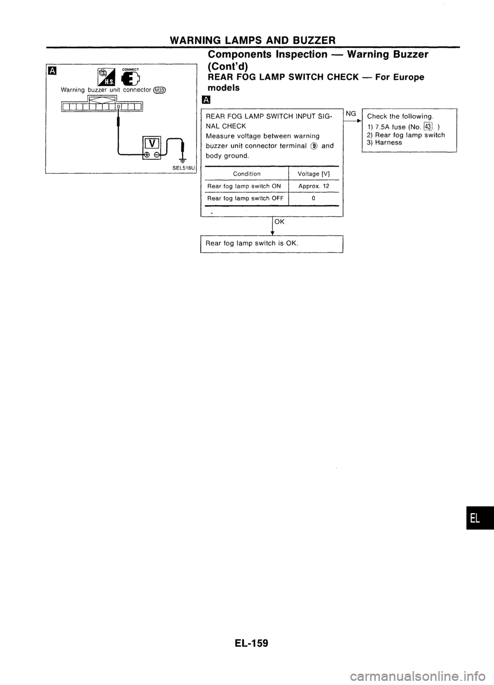
(Cont'd) REAR FOGLAMP SWITCH CHECK-For Europe
models
m
~i)
Warning buzzerunitconnector
@)
II
III
Iff
I
fl9LLO
I
SEL516U REAR
FOGLAMP SWITCH INPUTSIG-
NAL CHECK
Measure voltagebetween warning
buzzer unitconnector terminal@and
body ground.
Condition Voltage[V]
Rear foglamp switch ON Approx.12
Rear foglamp switch OFF 0
OK
Rear foglamp switch isOK.
EL-159 NG
Check thefollowing.
1) 7.5A fuse(No.
rm)
2) Rear foglamp switch
3) Harness
•
Page 532 of 1701
WIPERANDWASHER
Front Wiper andWasher/System Description
WIPER OPERATION
The wiper switch iscontrolled bya
lever
builtintothecombination switch.
There arethree wiper switch positions:
• LOspeed
• HIspeed
• INT (Intermittent)
With theignition switchinthe ACC orON position, powerissupplied
• through 20Afuse (No.
BID,
located inthe fuse block)
• towiper motor terminal
CID.
Low andhigh speed wiperoperation
Ground issupplied towiper switch terminal
@
through bodygrounds
(ill)
and
@.
When thewiper switch isplaced inthe LOposition, groundissupplied
• through terminal
@
ofthe wiper switch
• towiper motorterminal
@.
With power andground supplied, thewiper motor operates atlow speed.
When thewiper switch isplaced inthe HIposition, groundissupplied
• through terminal
@
ofthe wiper switch
• towiper motor terminal
(j).
With power andground supplied, thewiper motoroperates athigh speed.
Auto stopoperation
With wiper switch turned OFF,wiper motor willcontinue tooperate untilwiper armsreach windshield
base.
When wiper armsarenotlocated atbase ofwindshield withwiper switch OFF,ground isprovided
• from terminal
@
ofthe wiper switch
• towiper motorterminal @,inorder tocontinue wipermotoroperation atlow speed.
Ground isalso supplied
• through terminal
@
ofthe wiper switch
• towiper amplifier terminal
@
• through terminal
(J)
ofthe wiper amplifier
• towiper motorterminal
@)
• through terminal
@
ofthe wiper motor, and
• through bodygrounds
@,
@
and
@.D.
When wiper armsreach baseofwindshield, wipermotor terminals
@)
and
CID
are connected insteadof
terminals
@)
and
@.
Wiper motorwillthen stopwiper armsatthe PARK position.
Intermittent operation
With variable intermittent
The wiper motor operates thewiper armsataset interval ofapproximately 2to 20 seconds. Thisfea-
ture iscontrolled bythe wiper amplifier.
When thewiper switch isplaced inthe INT position, groundissupplied
• towiper amplifier terminal
(j)
• from wiper switch terminal
@
• through bodygrounds
(ill)
and
@.
• towiper motorterminal
@
• through thewiper switch terminal
@
• towiper switch terminal
@
• through wiperamplifier terminal
@
• towiper amplifier terminal
CID
• through bodygrounds
@,
@
and
@.D.
The desired intervaltimeisinput
• towiper amplifier terminal
@
• from wiper switch terminal
@).
The wiper motoroperates atlow speed atthe desired time
interval.
EL-160
Page 533 of 1701
WIPERANDWASHER
Front Wiper andWasher/System Description
(Cont'd)
Without variable intermittent
The wiper motor operates thewiper armsatan interval ofapproximately 7seconds. Thisfeature is
controlled byihe wiper amplifier.
When thewiper switch isplaced
in
the INT
position,
groundissupplied
• towiper amplifier terminal
CD
• from wiper switch terminal
@
• through bodygrounds
(ill)
and
(ill)
• towiper motor terminal
@
• through thewiper switch terminal
@
• towiper switch terminal
@
• through wiperamplifier terminal
@
• towiper amplifier terminal
CID
• through bodygrounds
@,
@
and
Qill).
WASHER OPERATION
With theignition switchinthe ACe orON position, powerissupplied
• through 20Afuse (No.
[1ID,
located inthe fuse block)
• towasher motorterminal
CD.
When thelever ispulled tothe WASH position, groundissupplied
• towasher motorterminal
@,
and
• towiper amplifier terminal
@
• from terminal
@
ofthe wiper switch
• through terminal
@
ofthe wiper switch, and
• through bodygrounds
(ill)
and
@D.
With power andground supplied, thewasher motoroperates.
When thelever ispulled tothe WASH position forone second ormore, thewiper motor operates atlow
speed forapproximately 3seconds toclean windshield. Thisfeature iscontrolled bythe wiper amplifier
in the same manner asthe intermittent operation.
EL-161
•
Page 534 of 1701
WIPERANDWASHER
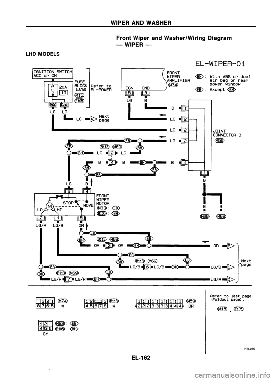
Front Wiper andWasher/Wiring Diagram
- WIPER-
LHD MODELS
EL-WIPER-01
Nextpage
JOINT
CONNECTOR-3
~
@:
WithABS
or
dual
air bagorrear
power window
@:
Except
@
FRONT
WIPER
AMPLIFIER
~
Refer to
EL-POWER.
FUSE
BLOCK
(JIB)
~
GNO
~lki=Jl
LG B
I
I__ ~-
:G~
---------------- LG~
~
.-------.~Ol---. LG~
<0>
@~
..J>
0
1 ~
LG..... :_: __ ~G__
~_H_-...
O-
B~
_ <0>
Ibi=Jl
O.R
t
O~:---
t& @ill)~
<0> ~
");.. OR~ OR
~O--------
OR~
.. --------IO~------- ..
~ @ill)~ .
<0>
O~ ~');..
LG/B~ LG/B
~O---
LG/B-(9-
4
@ill)~ ~
'1;;..
LG/R
-{Q
II
LG/R
~o--------------
LG/R-(g>
IGNITION
SWITCH
ACC orON
ffil2fTI@)
~W
fij'
I
If]]
@ill)
45678 W
ITIIIIl1lIITITI
~
~BR
Refer
tolast page
(Foldout page).
~~:@)
~ (8105):
@
GY
HEL086
EL-162
Page 535 of 1701
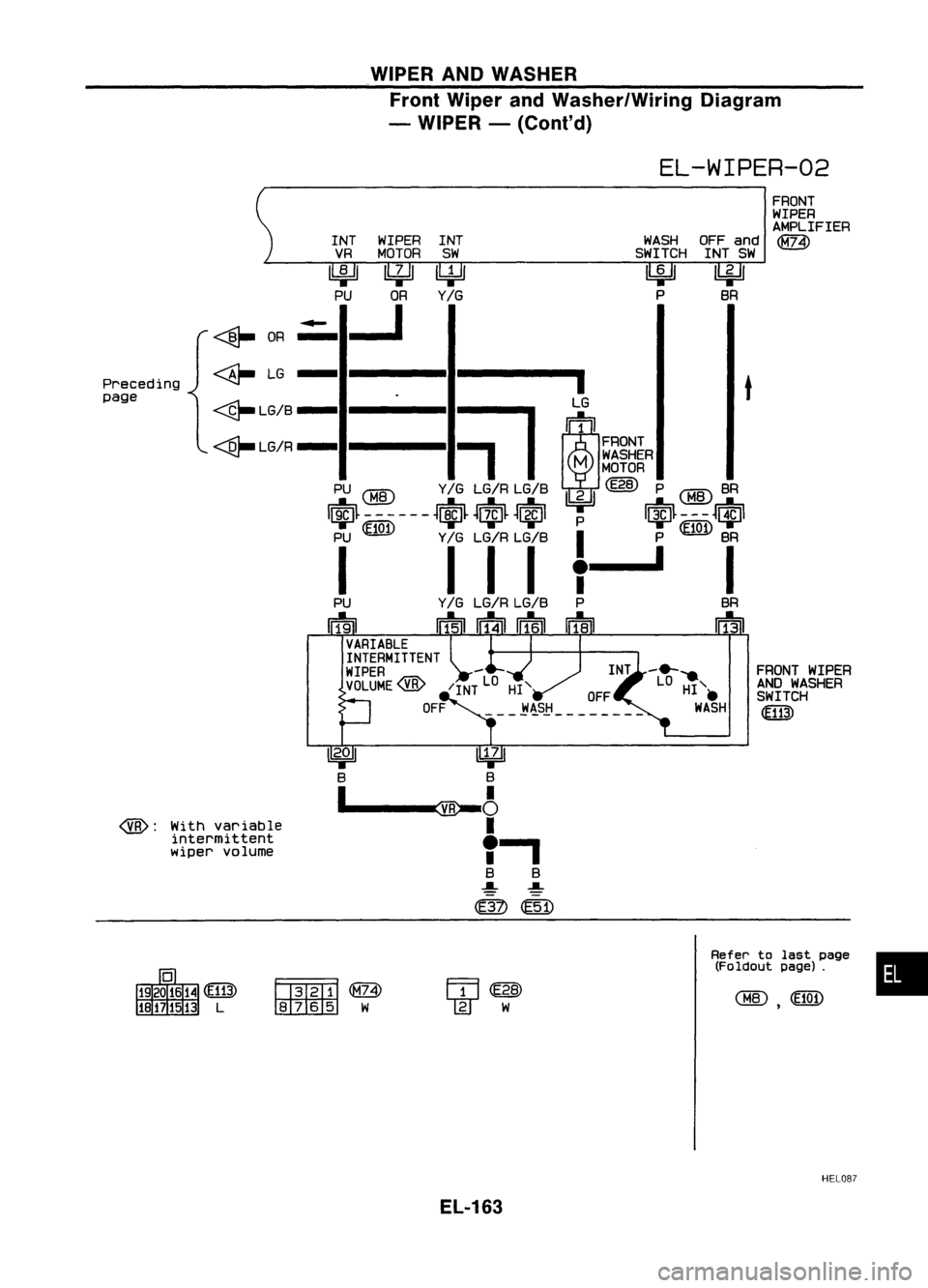
WIPERANDWASHER
Front Wiper andWasher/Wiring Diagram
- WIPER -(Cont'd)
EL-WIPER-02
•
FRONT
WIPER
AMPLIFIER
~
FRONT WIPER
AND WASHER
SWITCH
Refer tolast page
(Foldout page).
WASH
OFFand
SWITCH INTSW
~ ~
P SR
INT
SW
~
Y/G
INT
WIPER
VR MOTOR
~~ PU OR
.:.--J
Fl3T2fTI~
~W
~
OR
~ LG
- ----1.------1
LG
t
~LG/B-
=il
~1
~ / 1
FRONT
-....Qr-
LGR-
M
WASHER
MOTOR
PU
@
Y/G LG/R LG/S ~(E28) P
CHID
SR
IriJ~ -- ----
~ciJ~ ~~~
~EiJI
P
I~~---~ciJl
PU ~ Y/GLG/R LG/S
I
P~ SR
1 111,-' I
Y /G LG/R LG/S P SR
Irf5n
IT=f4i1rr=f6ft ~ rF!3n
With variable
intermittent
wiper volume
@:
Preceding
page
HEL08?
EL-163
Page 536 of 1701
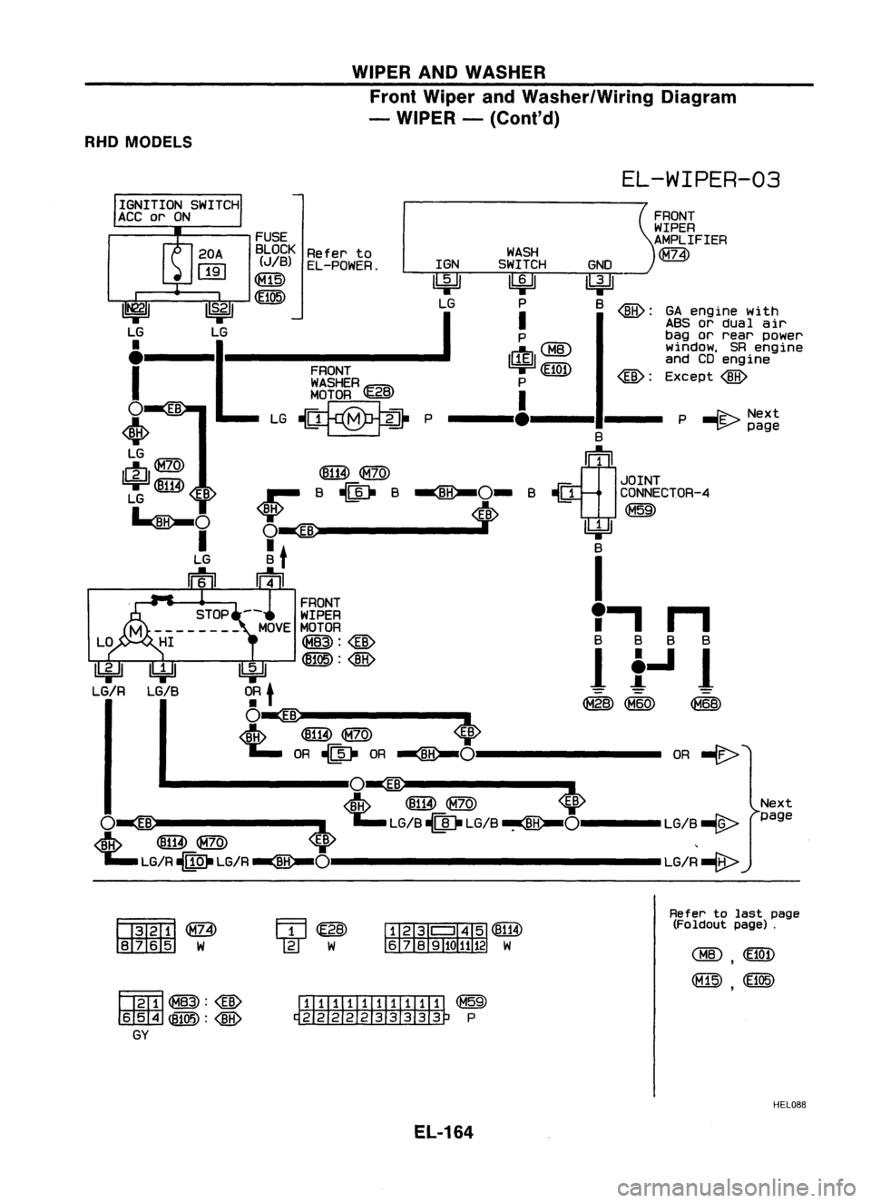
WIPERANDWASHER
Front Wiper andWasher/Wiring Diagram
- WIPER -(Cont'd)
RHD MODELS
EL-WIPER-03
Next
page
P
-I'E-
Next
~ page
OR
-€>
GA
engine with
ABS ordual air
bag orrear power
window, SRengine
and CDengine
Except
@
@:
GNO
lbjJJ
B
@:
B
~1
JOINT
~ CONNECTOR-4
~
~ B
I
I'
n
B BB 8
It-ll
~ (M60) ~
WASH
SWITCH
~ P
I
P
1$1 ~~:~
P
I
---'.---11---
@B)@
B~B~O-B
i>
FRONT
WASHER~B
MOTOR
'l:5.!3'
~P
FUSE
BLOCK Referto
(JIB) EL-POWER. IGN
00
I
S.21 LG
~
LG
•
.1
.
I
o
•
LG
LfJ@
1ki=Jl~
EB
LG
~O
I
LG
Iftu
IbjJl
0:
t
O~ ..-
<1ftp ~
@)
~ OR~ OR
~O--------
.. --------lO~ ..------.-
<1ftp ~
@)
<0>
O~
:L
~LG/B~ .LG/B~O----LG/B ~
~ ~@) ~ ,
';"LG/R-MO.LG/R~O---------------LG/R-e>
~@>
rn:rz:tm:I
W
~~:@
m
ITIillIIIIIIIIT
~
~P
Refer
tolast page
(Foldout page).
HEL088
EL-164
Page 537 of 1701
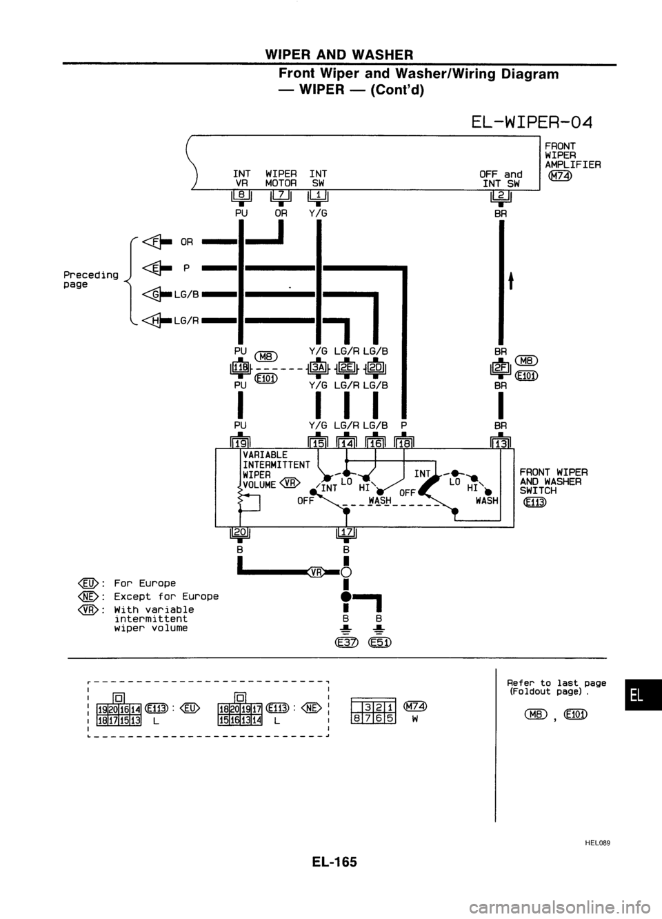
WIPERANDWASHER
Front Wiper andWasher/Wiring Diagram
- WIPER -(Co nt'd)
EL-WIPER-04
•
FRONT
WIPER
AMPLIFIER
l1ill)
FRONT WIPER
AND WASHER
SWITCH
~
Refer tolast page
(Foldout page).
SR
~CHID
~~
SR
I
SR
wrn
t
OFF
and
INT SW
~
SR
~ (M74)
~W
INT
WIPER INT
VR MOTOR SW
~~~
PU OR
Y/G
..J
=il
PU
CHID
Y
IG
LG/R LG/S
I$~ -- --- -
~$~
~l?fl~
~1(Ql1
PU ~ Y
IG
LG/R LG/S
I II I
<&-
OR
<@- P
<@-LG/S
<@-LG/R
For Europe
Except forEurope
With variable
intermittent
wiper volume
r---------------------------~
@:
@:
@:
Preceding
page
L ~
HEL089
EL-165
Page 538 of 1701
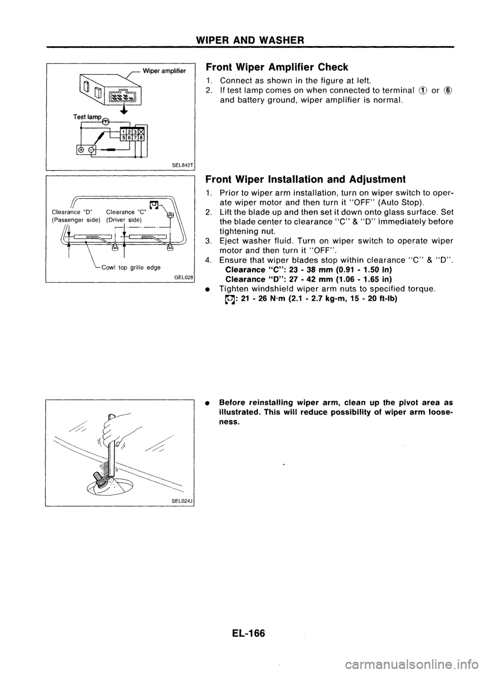
~Wiperamplifier
~~
t
Test lamp
SEL842TWIPER
ANDWASHER
Front Wiper Amplifier Check
1. Connect asshown inthe figure atleft.
2. Iftest lamp comes onwhen connected toterminal
CD
or
@
and battery ground, wiperamplifier isnormal.
GEL028
SEL024J Front
Wiper Installation andAdjustment
1. Prior towiper arminstallation, turnonwiper switch tooper-
ate wiper motor andthen turnit"OFF" (AutoStop).
2. Liftthe blade upand then setitdown ontoglass surface. Set
the blade center toclearance "C"
&
"D" immediately before
tightening nut.
3. Eject washer fluid.Turnonwiper switch tooperate wiper
motor andthen turnit"OFF".
4. Ensure thatwiper blades stopwithin clearance "C"
&
"D".
Clearance
"C":
23-38 mm (0.91 •1.50 in)
Clearance
"0":
27-42 mm (1.06 -1.65 in)
• Tighten windshield wiperarmnuts tospecified torque.
~: 21-26 N'm (2.1-2.7 kg-m, 15-20 ft.lb)
• Before reinstalling wiperarm,clean upthe pivot areaas
illustrated. Thiswillreduce possibility ofwiper armloose-
ness.
EL-166
Page 539 of 1701
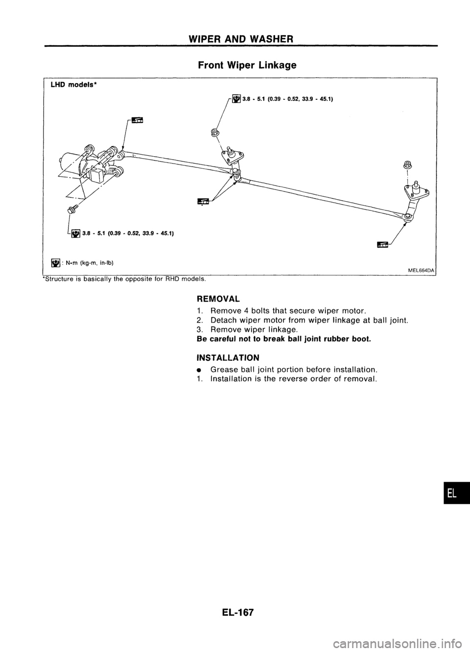
WIPERANDWASHER
Front Wiper Linkage
LHD models*
jfiiJ
'.8.5.1('."•'.52, ".9.45.1)
\
\
~: N.m(kg-m, in-Ib)
~
I
I
MEL664DA
'Structure isbasically theopposite forRHD models,
REMOVAL
1. Remove 4bolts thatsecure wipermotor.
2. Detach wipermotor fromwiper linkage atball joint.
3. Remove wiperlinkage.
Be careful nottobreak balljoint rubber boot.
INSTALLATION
• Grease balljoint portion beforeinstallation.
1. Installation isthe reverse orderofremoval.
EL-167
•
Page 540 of 1701
NOlzlehole
bore diameter
0.8 mm (0.031 in)
Front washer
RHDmodels GEL013WIPER
ANDWASHER
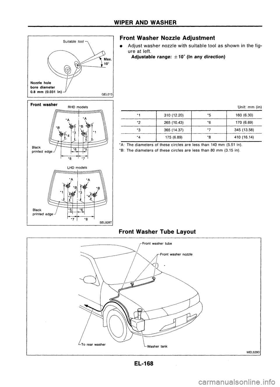
Front Washer NozzleAdjustment
• Adjust washer nozzlewithsuitable toolasshown inthe fig-
ure atleft.
Adjustable range::I:10
0
(Inany direction)
Unit:mm(in)
*8 "7
LHD models *1
310(12.20) *5
160(6.30)
*2 265(10.43) *6
170(6.69)
*3 365(14.37) *7
345(13.58)
*4 175(6.89) *8
410(16.14)
* A: The diameters ofthese circles areless than 140mm (5.51 in).
*8: The diameters ofthese circles areless than 80mm (3.15 in).
*7 *8
SEL92BT
FrontWasher TubeLayout
Front washer tube
Front washer nozzle
MEL629D
EL-168