NISSAN ALMERA N15 1995 Service Manual
Manufacturer: NISSAN, Model Year: 1995, Model line: ALMERA N15, Model: NISSAN ALMERA N15 1995Pages: 1701, PDF Size: 82.27 MB
Page 541 of 1701
WIPERANDWASHER
Rear Wiper andWasher/System Description
WIPER OPERATION
The rear wiper switch iscontrolled byaring built intothecombination switch.
There aretwo wiper switch positions:
• ON (LO speed)
• INT (Intermittent)
With theignition switchinthe ACC orON position, powerissupplied
• through 10Afuse (No.
W,
located inthe fuse block)
• torear wiper motorterminal
@,
and
• torear wiper relayterminal
CD.
Low speed wiperoperation
Ground issupplied torear wiper switch terminal
@
through bodygrounds
@
and
Cill).
When therear wiper isplaced inthe ON position, groundissupplied
• through rearwiper switch terminal
@
• torear wiper relayterminal
@.
The rear wiper relayisenergized andground issupplied
• torear wiper motor terminal
CD
• through rearwiper relayterminal
CID
• torear wiper relayterminal
CID
• through bodygrounds
@
and
Cill).
Auto stopoperation
With therear wiper switch turned OFF,rearwiper motor willcontinue tooperate untilwiper armreaches
rear window base.
When wiperarmisnot located atbase ofrear window withrearwiper switch OFF,rearwiper relayis
not energized andground issupplied
• torear wiper motorterminal
CD
• through rearwiper relayterminal
CID
• torear wiper relayterminal
@
• through rearwiper motor terminal
CID,
inorder tocontinue rearwiper motoroperation atlow speed.
Ground isalso supplied
• torear wiper motor terminal
@
• through bodygrounds
Cill),
@
and
(Qill).
When wiperarmreaches baseofrear window, rearwiper motorterminals
CD
and
@
are connected
instead ofterminals
CD
and
CID.
Rear wiper motor willthen stopwiper armatthe PARK position.
Intermittent operation
The rear wiper motor operates thewiper armonetime atlow speed atan interval ofapproximately 7
seconds. Thisfeature iscontrolled byrear wiper amplifier.
With theignition switchinthe ACC orON position, powerissupplied
• through 10Afuse (No.
W,
located inthe fuse block)
• torear wiper relayterminal
CD.
When therear wiper switch isplaced inthe INT position, groundissupplied •
• torear wiper amplifier terminal
@
• from rearwiper switch terminal
@
• through bodygrounds
@
and
Cill).
Ground isalso supplied
• torear wiper relayterminal
@
• through rearwiper amplifier terminal
@
• torear wiper amplifier terminal
CID
• through bodygrounds
@,
@ID
and
@.
Then therear wiper relayisenergized andground issupplied
• torear wiper motorterminal
CD
• through rearwiper relayterminal
CID
• torear wiper relayterminal
CID
EL-169
Page 542 of 1701
WIPERANDWASHER
Rear Wiper andWasher/System Description
(Cont'd)
• through bodygrounds
(ill)
and
@D.
With power andground supplied, therear wiper motor operates intermittently.
WASHER OPERATION
With theignition switchinthe ACC orON position, powerissupplied
• through 10Afuse (No.[]],located inthe fuse block)
• torear washer motorterminal
CD.
When thering isturned WASHposition, groundissupplied
• torear washer motorterminal
@,
and
• torear wiper amplifier terminal
CD
• from terminal
@
ofrear wiper switch
• through terminal
@
ofrear wiper switch, and
• through bodygrounds
(ill)
and
@D.
With power andground issupplied, therear washer motoroperates.
The rear wiper motor operates whenthering isturned toWASH position forone second ormore and
for approximately 3seconds afterthering isreleased. Thisfeature iscontrolled bythe rear wiper
amplifier inthe same manner asthe intermittent operation.
EL-170
Page 543 of 1701
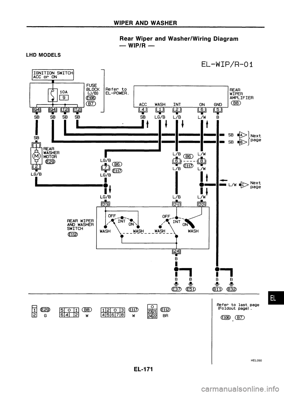
WIPERANDWASHER
Rear Wiper andWasher/Wiring Diagram
- WIP/R-
LHD MODELS
EL-WIP/R-01
IGNITION SWITCH
ACC orON
FUSE
BLOCK Refer
to
REAR
(JIB) EL-POWER.
WIPER
(flOG)
AMPLIFIER
WASH
INT ONGND
@)
~
l!4Jl
~ ~
lki=H
SB LG/B
LIB L/W
B
I
t
f
f
t
-
-
-
SB
~}Next
-
-
-
SB
-@>
page
LIB @ L/W
LG/B@
~----$
ctl
B6
LIB
(ffiZ)
L/w
~(ffiZ)
LG/B
I
I
t
I
~
If
.-
_
L/W
-@:>
Next
Jw
f
page
LG/B
':31 12.21
10A
W
I
Q.4
I I
Q.41 IIT.21
I
T.21
SB SBSBS8
!
I
I'
~1
REAR
M
WASHER
MOTOR
~
~
LG/B
1 _
REAR WIPER
AND WASHER
SWITCH
~
1Tl~
rgJ
G
~@
~(El17)
~W ~W i~
2422 BR
f,
B B
~ ~
~~
Refer tolast page
(Foldout page).
•
HEL090
EL-171
Page 544 of 1701
![NISSAN ALMERA N15 1995 Service Manual WIPERANDWASHER
Rear Wiper andWasher/Wiring Diagram
- WIP/R -(Cont'd)
EL-WIP/R-02
1--
1•
B
~@Qg)
ICiJI@
B
I
I.
B B
~ ~
<ID]) ~
t
B
m
~
(0101)
SB~SB
~
Y!L
I I
t
OR ~ Y!L
~----$
NISSAN ALMERA N15 1995 Service Manual WIPERANDWASHER
Rear Wiper andWasher/Wiring Diagram
- WIP/R -(Cont'd)
EL-WIP/R-02
1--
1•
B
~@Qg)
ICiJI@
B
I
I.
B B
~ ~
<ID]) ~
t
B
m
~
(0101)
SB~SB
~
Y!L
I I
t
OR ~ Y!L
~----$](/img/5/57349/w960_57349-543.png)
WIPERANDWASHER
Rear Wiper andWasher/Wiring Diagram
- WIP/R -(Cont'd)
EL-WIP/R-02
1--
1•
B
~@Qg)
ICiJI@
B
I
I.
B B
~ ~
t
B
m
~
(0101)
SB~SB
~
Y!L
I I
t
OR ~ Y!L
~----$
OR
@)
Y!L
I I
OR
@)
Y!L
I$~ -
~1-
iclJl
OR ~ Y!L
..-J
SB OR
111 ~~rEAR
WIPER
RELAY
1!:i=Jl1biJl4Jl
{~
SB
~ SB----.
Preceding
page
L/WBY/L
Preceding
---15l-
L7;-----'
I
page ~
I.
B B
~ ~
~ (E51)
fIlii'
I'~
45678 W~
(E15)
T
B
~
(E117)
~W
~
(0106)
~W
HEL091
EL-172
Page 545 of 1701
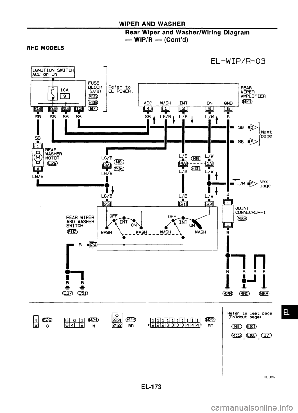
WIPERANDWASHER
Rear Wiper andWasher/Wiring Diagram
- WIP/R -(Conl'd)
RHD MODELS
EL-WIP/R-03
REAR
WIPER
AMPLIFIER
@)
S8 ~}Next
page
S8 ~
L/8
<:BID
L!W
$----$
L/8
(Eiot)
L!W
I •
I_t.-
_L!W
JF--.-
Nex
t
I
~page
L/W
f
B
~ rn
1
JOINT
CONNECROR-1
@
lbi=!J
B
I
i-,
n
8 888
1
f..l
1
~ (M60) ~
Refer
to
EL-POWER.
OF~_. __
/ INT~"
WASH ~A.?1j _
REAR
WIPER
AND WASHER
SWITCH
~
r
8~4
f,
B 8
..a.. ..a..
~ (51)
FUSE
8LOCK
(JIB)
(f1@
I
~41 ~UN;!
II
T.21
tkjJ
S8 SBSB 5B S8
t
LG/8
J
L/8
J
L/W
t
B
!
I
1_
1-- ----
-_1-
=:=:,=:
(~M~
II:~~EA
MOTOR LG/B
U:i=Jl ~
1$1
LG/B LG/B
1
1.
1
I
J
LG/B
12';1
[ID"""Q]]]~
ffil3ill]
W
i~
2422 8R
ITIIIIITIIITITI
@
~8R
Refer
tolast page •
(Foldout page).
<:BID ~
,
(M15) (Et06)
(]V
,
.
HEL092
EL-173
Page 546 of 1701
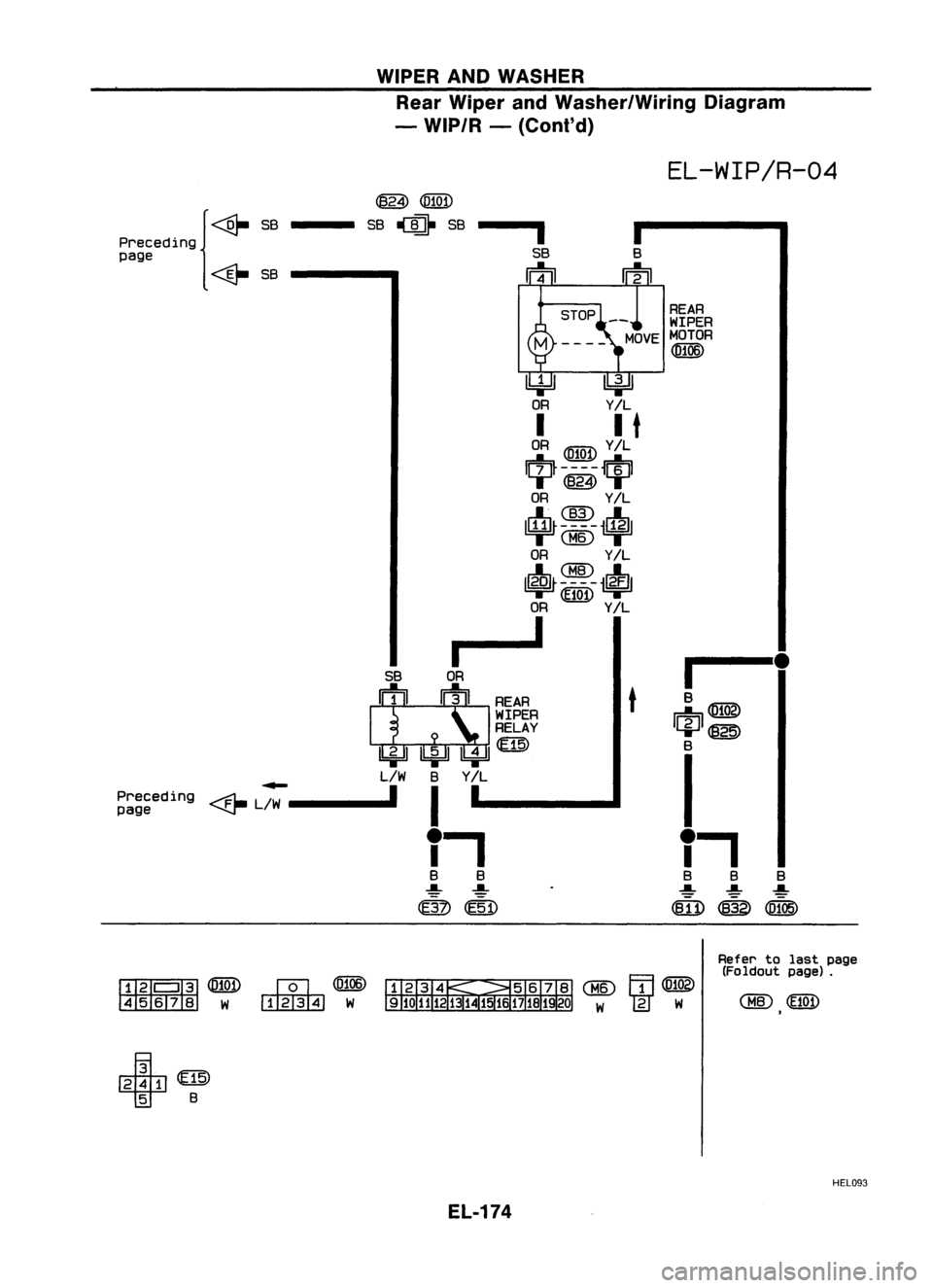
WIPERANDWASHER
Rear Wiper andWasher/Wiring Diagram
- WIP/R -
(Co nt'd)
EL-WIP/R-04
1---
B
ffi@
+@
B
I
f.
B BB
~ ~
.....
mD@~
t
REAR
-- t
WIPER
MOVE MOTOR
<[l106)
I
SB
m
ILi=ll
Y/L
I I
t
OR
@QD
Y/L
1Fh----m
T~T
OR Y/L
...L(]ID...L
11.llJ~ --- -il1,gJl
-.-@ -.-
OR Y/L
...LCBID...L
1l6QJ1- --- -
i~1
=r~
OR Y/L
r---I
~
@QD
SB~SB
SB OR
II!I ~rAA
WIPER
RELAY
1bjJI1bj:JI4=JI
L/W BY/L
~L~
I
I
f.
B B
~ ~
rn
@D
Preceding
{
page
~SB
Preceding
page
fH!/'
I
Ill!
@QD ~
<[l106)
45678 W~ W
Refer
tolast page
(Foldout page).
~@
T
B
HEL093
EL-174
Page 547 of 1701
~~:;"f1.'
~
C!E:TIJ
!II8EITJ
SEL846TWIPER
ANDWASHER
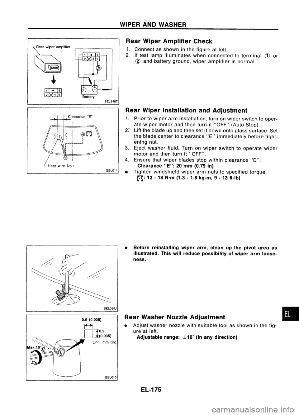
Rear Wiper Amplifier Check
1. Connect asshown inthe figure atleft.
2.
If
test lamp illuminates whenconnected toterminal
CD
or
@
and battery ground, wiperamplifier isnormal.
Clearance "E"
GEL014
SEL024J
0.9 (0.035)
~
OJ
O.9
(0.035)
Unit: mm(in)
GEL015 Rear
Wiper Installation andAdjustment
1. Prior towiper arminstallation, turnonwiper switch tooper-
ate wiper motor andthen turnit"OFF" (AutoStop).
2: Liftthe blade upand then setitdown ontoglass surface. Set
the blade center toclearance "E"immediately beforetight-
ening nut.
3. Eject washer fluid.Turnonwiper switch tooperate wiper
motor andthen turnit"OFF".
4. Ensure thatwiper blades stopwithin clearance "E".
Clearance
"E":
20mm (0.79 in)
• Tighten windshield wiperarmnuts tospecified torque.
~: 13-18 N.m (1.3-1.8 kg-m, 9-13 ft-Ib)
• Before reinstalling wiperarm,clean upthe pivot areaas
illustrated. Thiswillreduce possibility ofwiper armloose-
ness.
Rear Washer NozzleAdjustment
• Adjust washer nozzlewithsuitable toolasshown inthe fig-
ure atleft.
Adjustable range:
::l::
10°
(Inany direction)
EL-175
•
Page 548 of 1701
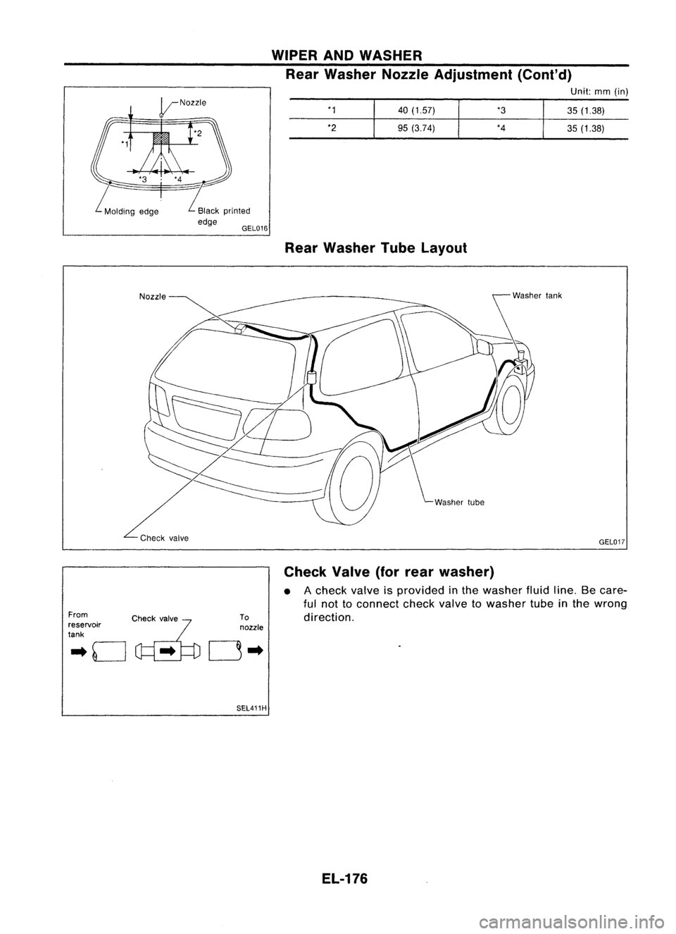
WIPERANDWASHER
Rear Washer NozzleAdjustment (Cont'd)
Unit:mm(in)
*1 40(1.57) *3
35(1.38)
*2 95(3.74) *4
35(1.38)
Rear Washer TubeLayout
GEL017
From
.. 0
c~....
~fo
reservoir
tank
To
nozzle
0"
SEL411H Check
Valve(forrear washer)
• Acheck valveisprovided inthe washer fluidline.Becare-
ful not toconnect checkvalvetowasher tubeinthe wrong
direction.
EL-176
Page 549 of 1701
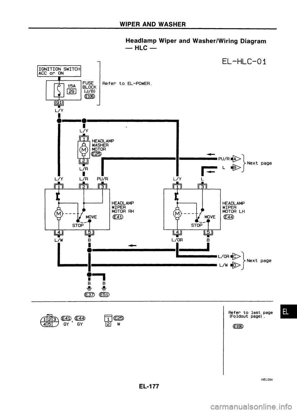
WIPERANDWASHER
Headlamp WiperandWasher/Wiring Diagram
-HLC-
EL-HLC-01
IGNITION SWITCH
ACC
or
ON
FUSERefertoEL-POWER.
BLOCK
(J/B)
(fi06)
15A
1291
---Ie----------- ..
•
L/Y
(~IIHEA~A~
WASHER
M MOTOR
~ ~
IIIII----------II------PU/R~}
Ibj:U ~
Nextpage
L'R
I.._
L~
L/R PU/R L/YL
m
IFh
m
IFh
L/Y
m
HEADLAMP
WIPER
MOTOR LH
MOVE
ffi
STOP
HEADLAMP
WIPER
MOTOR RH
~
MOVE
STOP
~ IbjdJ
L/W B B
L
el'
1
-----L/OR ~}
..fr:\--.....
Nextpage
L/W
.,g....-
,.
B B
~ ~
~ (E51)
~ffi.
~GY GY
Refer
tolast page •
(Foldout page).
HEL094
EL-177
Page 550 of 1701
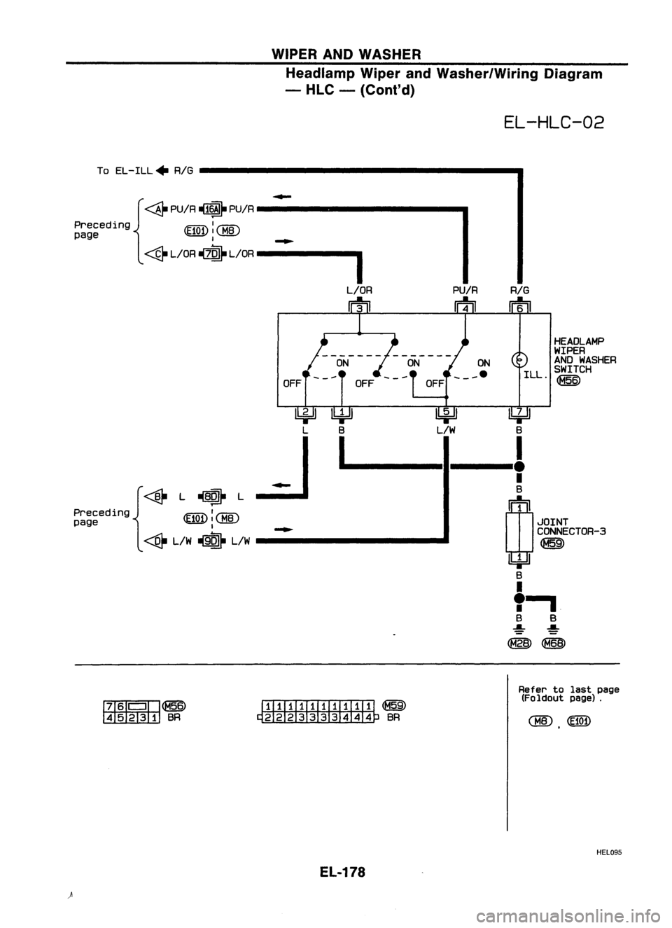
WIPERANDWASHER
Headlamp WiperandWasher/Wiring Diagram
- HLC -(Cont'd)
EL-HLC-02
To EL-ILL. RIG
HEADLAMP
WIPER
AND WASHER
ILL SWITCH
.~
PU/R
RIG
m m
OFF
ON
ON
___ e
OFF
OFF
{~
PU/R~ PU/R
Preceding ~:~
page
1-..
~L/OR ~L/OR -----_
~ ~~
B L/WB
I~_-.--! .
•
B
~1
.JOINT
CONNECTOR-3
~
lbi=Jl
B
I
,-,
B B
~ ~
~~
~
L
..J
{~L~L
Preceding
~I~
page ~:~
-..
ffiII'
I'@~
45231 BR mIIIITIillIIITI
~
~BR
Refer
tolast page
(Foldout page).
HEL095
EL-178