NISSAN ALMERA N15 1995 Service Manual
Manufacturer: NISSAN, Model Year: 1995, Model line: ALMERA N15, Model: NISSAN ALMERA N15 1995Pages: 1701, PDF Size: 82.27 MB
Page 601 of 1701
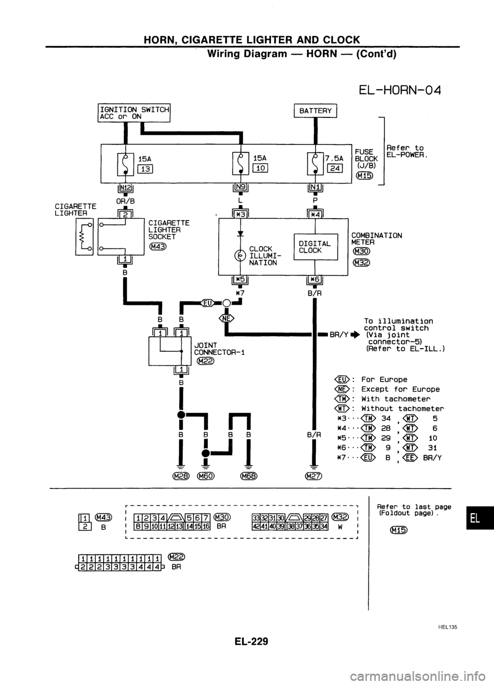
HORN,CIGARETTE LIGHTERANDCLOCK
Wiring Diagram -HORN -(Cont'd)
EL-HORN-04
•
Refer
tolast page
(Foldout page).
FUSE
Referto
BLOCK EL-POWER.
(JIB)
([@
COMBINATION
METER
~
7.5A
1241
~
B/R
@: For
Europe
@:
Except forEurope
@: With
tachometer
@:
Without tachometer
*3"'@ 34
@
5
*4 ... @
28
'
6
B/R
,
*5"'@ 29
1
*6"'@
9
'
,
*7"'@ B
@
BR/Y
,
DIGITAL
CLOCK
15A
[]Q]
CLOCK ILLUMI-
NATION
Toillumination
control SWitch
-------II-BR/Y+
(Viajoint
connector-5)
(Refer toEL-ILL.)
CIGARETTE
LIGHTER
SOCKET
~
15A
mJ
r-----------------------------------,
[[il~
rn
B
CIGARETTE
LIGHTER
~ 10-----,- ,
~ B
L, ~
~o.:i
JOINT
CONNECTOR-1
~
~ B
I
" n
B
BBB
1
!..J
1
(M28) (M60) (M68)
L ~
I1IIIIIillIillI ~
~BR
HEL135
EL-229
Page 602 of 1701
REARWINDOW DEFOGGER ANDDOOR MIRROR DEFOGGER
System Description (Formodels withdaytime
light system)
For models withoutdaytime lightsystem, refertowiring diagrams, EL-233and234.
The rear window anddoor mirror defogger systemiscontrolled bythe rear window defogger timer.
Power issupplied atall times
• torear window defogger relayterminal
@
• through 20Afuse (No.[[],located inthe fuse block).
With theignition switchinthe ACC orON position, powerissupplied
• tomirror defogger relayterminal
@
• through 10Afuse (No.
InJ,
located inthe fuse block).
With theignition switchinthe ONorSTART position, powerissupplied
• torear window defogger relayterminal
CD
• through 10Afuse (No.
[2ID,
located inthe fuse block)
• torear window defogger timerterminal
CD
• through 7.5Afuse(No.[[],located inthe fuse block).
Ground issupplied
• torear window defogger switchterminal
@
and
• torear window defogger timerterminal
@
• through bodygrounds
@
and
@ID.
Operation
The ignition switchmustbeinthe ONorSTART position fordefogger operation.
With therear window defogger switchinthe ONposition andforapproximately 12-16 minutes afterthe
rear window defogger switchhasturned toOFF from ON,ground issupplied
• through terminal
CD
ofthe rear window defogger switch
• torear window defogger timerterminal
@.
Terminal
@
ofthe rear window defogger timerthensupplies groundtorear window defogger relay
terminal
@.
With power andground supplied, rearwindow defogger relayisenergized.
For rear window defogger system,powerissupplied
• through terminal
CID
ofthe rear window defogger relay
• tocondenser terminal
CD
• through terminal
@
ofthe condenser
• tothe rear window defogger terminal
CD.
For mirror defogger system,powerissupplied
• through terminal
CID
ofthe rear window defogger relay
• tomirror defogger relayterminal
CD.
Ground issupplied
• through bodygrounds
@
and
@ID
• tomirror defogger relayterminal
@.
With power andground supplied, mirrordefogger relayisenergized.
• through mirrordefogger relayterminal
CID
• toeac
r
doormirror defogger terminal
@.
Ground issupplied
• torear window defogger terminal
@
• through bodyground
and
• toeach doormirror defogger terminal
CD
• through bodygrounds
@
and
@ID.
With power andground supplied, eachdefogger filamentheatsanddefogs therear window anddoor
mirror.
When thesystem isactivated, therear window defogger indicatorilluminates inthe rear window defog-
ger switch.
Power issupplied
• toterminal
CID
ofthe rear window defogger switch
• from terminal
CID
ofthe rear window defogger relay.
Terminal
@
ofthe rear window defogger switchisgrounded throughbodygrounds
@
and
@.
EL-230
Page 603 of 1701
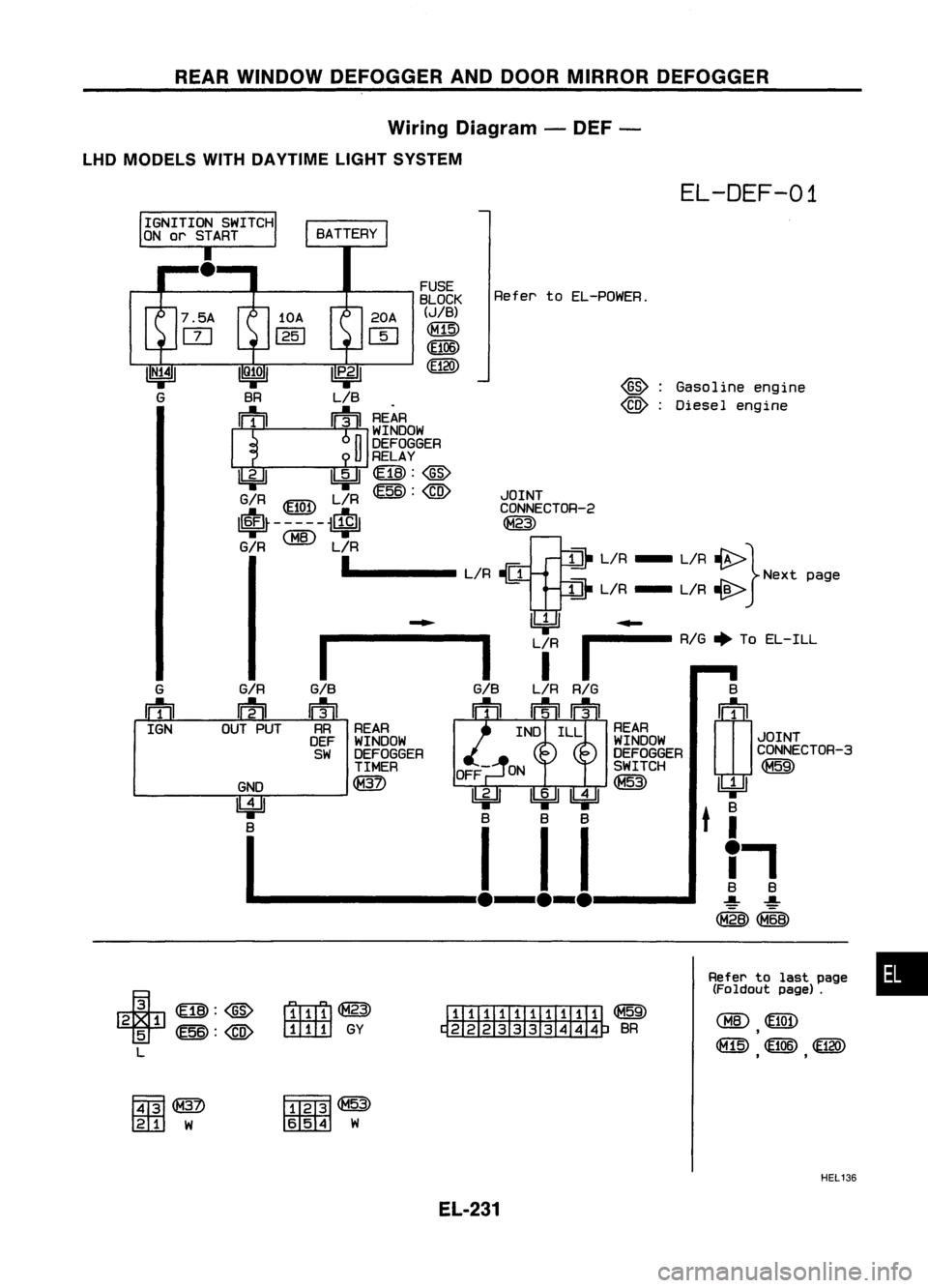
REARWINDOW DEFOGGER ANDDOOR MIRROR DEFOGGER
Wiring Diagram -DEF -
LHD MODELS WITHDAYTIME LIGHTSYSTEM
EL-DEF-01
Gasoline engine
Diesel engine
@:
@) :
Refer
toEL-POWER.
FUSE
BLOCK
(JIB)
CM15)
~06)
CE120)
20A
W
II
P•2
1
LIB
! ~
~¥~~OW
I
J
12~r~~GER
~ 1!:iJI~:@
G/R L/R~:
@
JOINT
~ ~ ~ CONNECTOR-2
I~~-----~ ~
G/R
1. L/R-[J
Et
L/R - L/R~} Nextpage
!di
L/R - L/R~
~ ~~
1-------
Lf
I
RIG
+
ToEL-ILL
G/B
L/R
RIG
B
n1il ~
n=tD (!J1
~f} ~¥~~OW INDILL ~¥~~OW JOINT
SW DEFOGGER DEFOGGERCONNECTOR-3
TIMER OFF SWITCH~
GND ~ ~
11111
11211 9F
~ ~t
B.
B BBB
I--ll-l-l 11
(M"2B)
G/R
~
OUT PUT
G
IftlJ
IGN
+
~:@
2 1
5
~:@
L
r1ITr1l~
ITITITJ
GY
ITIIIII:illTIIi
~
~BR
Refer
tolast page •
(Foldout page).
F.ffi1
tm::l
W
fffffi~
rn:mrn
W
HEL136
EL-231
Page 604 of 1701
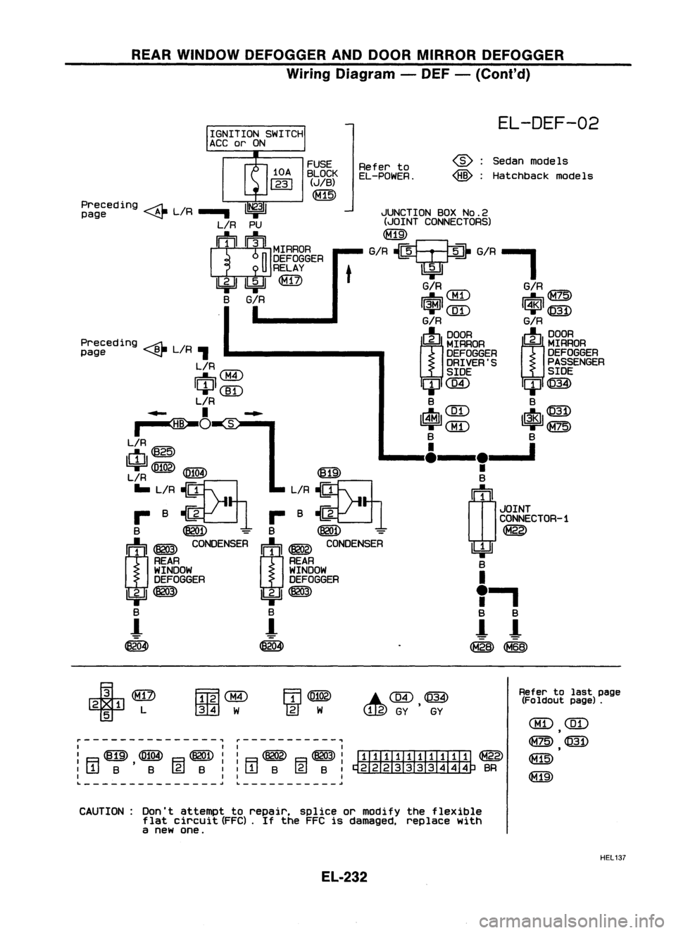
REARWINDOW DEFOGGER ANDDOOR MIRROR DEFOGGER
Wiring Diagram -DEF -(Cont'd)
JUNCTION BOXNo.2
(JOINT CONNECTORS)
G/R?G/R-'
EL-DEF-02
Sedan models
Hatchback models
@:
@:
G/R
IUT\
G/RIG=7c:\
~\.Mi.J ~~
1~1
([D
I~l
@)
G/R G/R
(J)
~RAOA
m~~~
DEFOGGER
DEFOGGER
DRIVER'S PASSENGER
SIDE SIDE
ClJC@ ClJ@)
B B
IrtJl ~~~ ~ 1$1~~~
B B
____ I&__
le__ '
•
B
(1J
1
JOINT
CONNECTOR-1
~
~ B
I
"
a
a
!- !-
~~
Refer
to
EL-POWER.
t
FUSE
BLOCK
(JIB)
~
Preceding ~L/R
1~31
page ~.....
L/R PU
I
1
1
1~IIMrRAOA
n
DEFOGGER
U
RELAY
Ibi=U ~
@)
B
G/R
I
Preceding ~L/R
page ~,
L/R
IU'7"\
~0:M.I
ICIJI(]I)
L/R
..... I~...
~O
~S:-"
L/R
ctI@
~
1619'
L/R ~
IE!.!3I
... L/R ~ L/R~
r- B~1 r-B~1
B ~
=
B
@QD -
m ~
~NSER
I:j:'l ~
CO~SER
REAR REAR
WINDOW WINDOW
DEFOGGER DEFOGGER
IbjJ ~
Ibi=JI~
B B
-!
!-
~ ~
r---------------, ~-----------,
I II I
I ~ ~ ~II ~ ~I
ITIIIII.TIII:TI ~
:[jjB'B (gjB::rTIB @lB:~BR
I II I
L
~~ ~
+
2 1 L
5
FmlaID
001
W
.C@,~
Refer
tolast page
(Fo ldout page).
CBD
(ill)
,
~@
~
CAUTION: Don'tattempt torepair. spliceormodify theflexible
flat circuit (FFC).
If
the FFC isdamaged, replacewith
a new one.
HEL137
EL-232
Page 605 of 1701
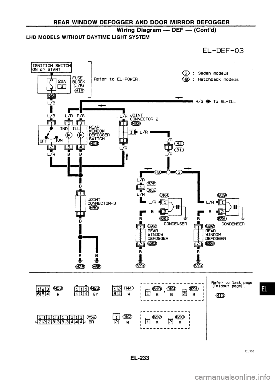
REARWINDOW DEFOGGER ANDDOOR MIRROR DEFOGGER
Wiring Diagram -DEF -(Conl'd)
LHD MODELS WITHOUT DAYTIMELIGHTSYSTEM
EL-DEF-03
•
Refer
tolast page
(Foldout page).
~
L/R~
... B
~1
B
@QD
=
r:
j
:'I~
CONDENSER
REAR
WINDOW
DEFOGGER
lbjJJ~
B
!-
~
-
~:
Sedanmodels
~ :Hatchback models
~----------------~
: F.=1
@
,(0104) B~ :
'WB B@B
I
I I
L ~
filllaID
@g]
W
-----------------
RIG.
ToEL-ILL
r1TTI1l@
IT1IITI
GY
~~g~K
RefertoEL-POWER.
(JIB)
~
i
L/R JOINT
. CONNECTOR-2
[¥
1 ~
REAR
~~~gg~ER ~L/R
---I
SWITCH L/R
~ II
J
II
I"TI'A\
~ ~ ~~
~ ~ L/R ICIJI
(]I)
L/R B
B
I
t
LIR
Ll:!
~!
s
I
L/R
B
IcIJlm~~
rn~
I
L/R~
JOINT
L~
CONNECTOR-3 L/R~
II UI ...B~
~ B~
=
I
m~
CONOENsrn
REAR
WINDOW
tt
ll
DEFOGGER
lbjJJ~
B
-!- -!-
1
~ (868)
ffiill1~
~ W
I1III1IIIIIIIII ~
~BR r-------------.,
: F.=1~
B~:
I
W
B
@
B
I
I I
L
j
HEL138
EL-233
Page 606 of 1701
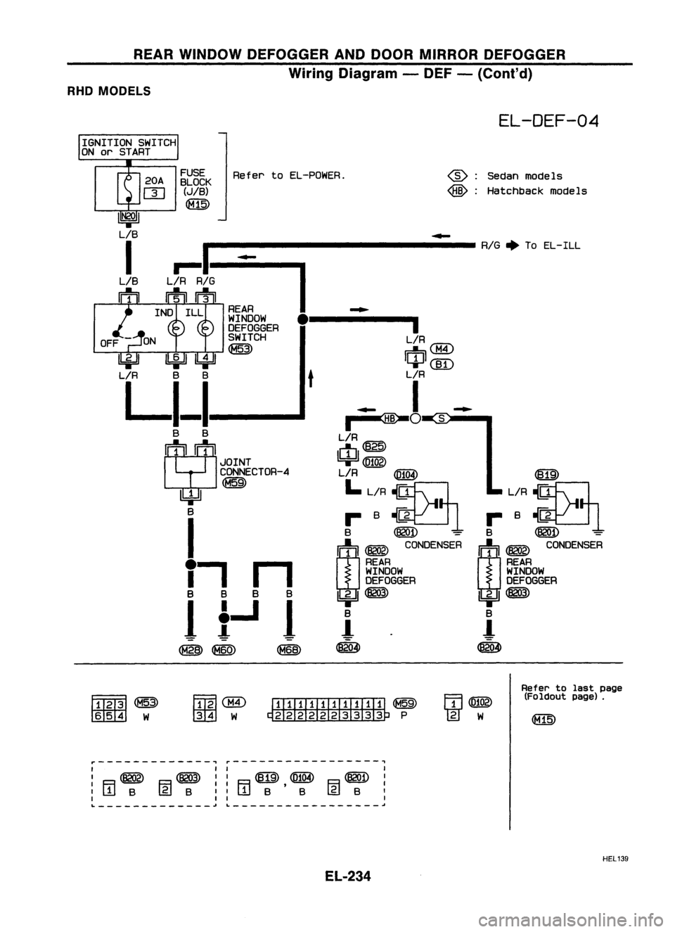
REARWINDOW DEFOGGER ANDDOOR MIRROR DEFOGGER
Wiring Diagram -DEF -(Cont'd)
RHO MODELS
EL-DEF-04
~ :Sedan models
~ :Hatchback models
-
----------------
RIG.
ToEL-ILL
~~8~K
Re
f
er toEL-POWER.
(JIB)
~
REAR
....
WINDOW
•
•
DEFOGGER
OFF SWITCH
L/R@
~
mM4
~
[}Jew
L/R
BB
t
L/R
LI_I
I
-
....
~O
S
B B
L/R~
S
(j]
25
JOINT
1!4JI@!Qg)
CONNECTOR-4 LlR
@@
~
~
LL~8 L/R8
~
B rB~rB~
I
B
~
=
B ~
=
m~
C~SEA
m~
C~NSER
T,
n
REAR
REAR
WINDOW WINDOW
DEFOGGER DEFOGGER
B
B
B
B
1biJI~ 1biJI~
1
1...1
1
B
B
-!
1
!
@ @
~
(8204)
~
~~
~ W
~
@ [ill]I[ill]I[il ~
~ W~ P
m@
Ww
Refer
tolast page
(Foldout page).
,..--------------,
,..-----------------.,
I II I
I ~ ~':
R~,([)104) 8~:
:~B rg)B:'L!JB B@JB
I
I I, I
'- .J
L
.I
HEL139
EL-234
Page 607 of 1701
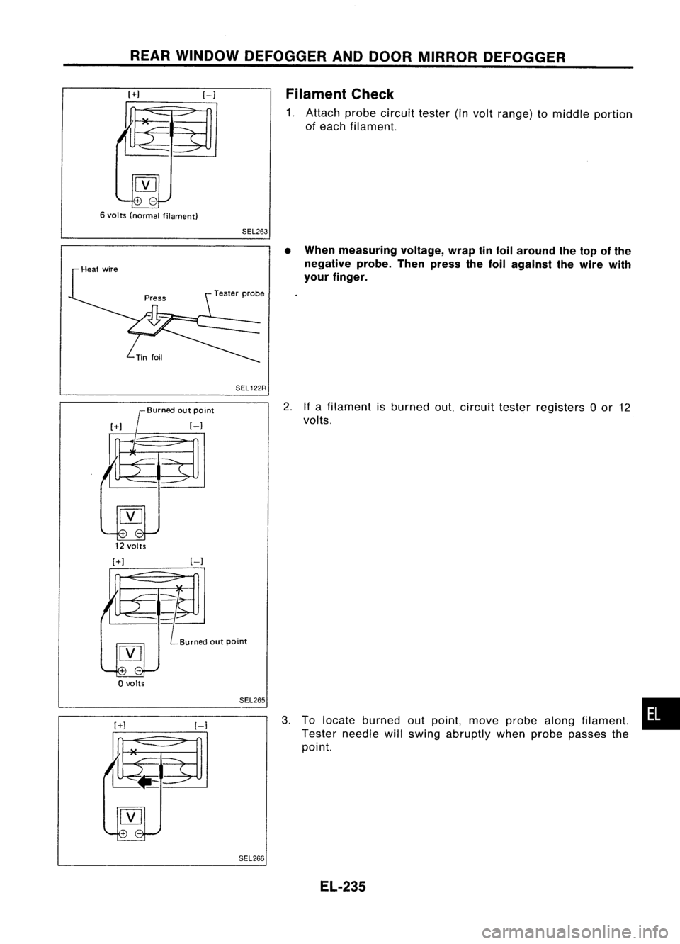
REARWINDOW DEFOGGER ANDDOOR MIRROR DEFOGGER
[+1
6 volts (normal filament)
[-1
SEL263 Filament
Check
1. Attach probecircuit tester(involt range) tomiddle portion
of each filament.
SEL 122R
Burned outpoint
12 volts
•
When measuring voltage,wraptinfoil around thetop ofthe
negative probe.Thenpress thefoil against thewire with
your finger.
2. Ifa filament isburned out,circuit testerregisters 0or 12
volts.
[+1
[-]
o
volts
SEL265
SEL266
3.
To locate burned outpoint, moveprobe alongfilament.
Tester needle willswing abruptly whenprobe passes the
point.
EL-235
•
Page 608 of 1701
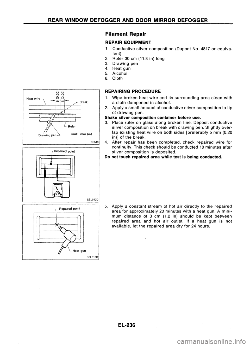
REARWINDOW DEFOGGER ANDDOOR MIRROR DEFOGGER
Filament Repair
REPAIR EQUIPMENT
1. Conductive silvercomposition (DupontNo.4817 orequiva-
lent)
2. Ruler 30cm (11.8 in)long
3. Drawing pen
4. Heat gun
5. Alcohol
6. Cloth
Unit: mm(in)
REPAIRING
PROCEDURE
1. Wipe broken heatwire anditssurrounding areaclean with
a cloth dampened inalcohol.
2. Apply asmall amount ofconductive silvercomposition totip
of drawing pen.
Shake silvercomposition containerbeforeuse.
3. Place ruleronglass along broken line.Deposit conductive
silver composition onbreak withdrawing pen.Slightly over-
lap existing heatwire onboth sides [preferably 5mm (0.20
in)] ofthe break.
4. After repair hasbeen completed, checkrepaired wirefor
continuity. Thischeck should beconducted 10minutes after
silver composition isdeposited.
Do not touch repaired areawhile testisbeing conducted.
BE540
SEL012D
Break
R .d
epalre point
j
IrJ
t..@.!.
-
--
Heat
wire
Repairedpoint
5.
Apply aconstant streamofhot airdirectly tothe repaired
area forapproximately 20minutes withaheat gun.Amini"-
mum distance of3cm (1.2 in)should bekept between
repaired areaandhotairoutlet. Ifa heat gunisnot
available, letthe repaired areadryfor24hours.
SEL013D
EL-236
Page 609 of 1701
![NISSAN ALMERA N15 1995 Service Manual AUDIOANDANTENNA
Audio/System Description
Refer toOwner's Manualforaudio system operating instructions.
Power issupplied atall times
• through 7.5Afuse(No.
[2]],
located inthe fuse block)
• to NISSAN ALMERA N15 1995 Service Manual AUDIOANDANTENNA
Audio/System Description
Refer toOwner's Manualforaudio system operating instructions.
Power issupplied atall times
• through 7.5Afuse(No.
[2]],
located inthe fuse block)
• to](/img/5/57349/w960_57349-608.png)
AUDIOANDANTENNA
Audio/System Description
Refer toOwner's Manualforaudio system operating instructions.
Power issupplied atall times
• through 7.5Afuse(No.
[2]],
located inthe fuse block)
• toradio terminal
@,
and
• tocompact diskdeck terminal
@.
With theignition switchinthe ACC orON position, powerissupplied
• through 15Afuse (No.
[j]],
located inthe fuse block)
• toradio terminal
@),
and
• tocompact diskdeck terminal
@.
Ground issupplied throughthecase ofthe radio.
When theradio power knobispushed tothe ON position, audiosignals aresupplied
• through radioterminals 1,2, 3,
4,
13,
)4,
15and 16
• tothe door, pillarandrear speakers.
EL-237
•
Page 610 of 1701
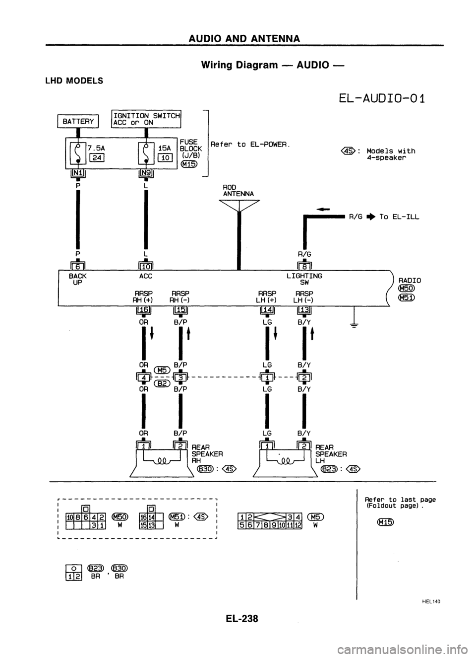
AUDIOANDANTENNA
Wiring Diagram -AUDIO -
LHD MODELS
EL-AUDIO-01
RADIO
Q3W
Models
with
4-speaker
ROD
ANTENNA
~~gEK
RefertoEL-POWER.
(JIB)
~
L
~
ACC
....
~ AIG~To EL-ILL
RIG
m
LIGHTING
SW
RRSP RRSP RRSPRRSP
RH
(+)
RH(-) LH
(+)
LH(-)
l!JjJJ ~ ~~
OR B/P LGB/Y
I. It I.It
OR
IciJ~ -~ -
tiJ~ -------- - --
~ciJ~ ---
~ciJl
OR ~ B/P LGB/Y
I I II
P
m
BACK
UP
ORB/P
JL:QQ~EAA
SPEAKER
RH
~:@
r-------------------------,
I
I
~:@I
W
I
I
I
L
~
&~@)
5 6
TII;uo
1112W
Refer
tolast page
(Foldout page).
[Q]~~
I]lg]
BR•BR
HEL140
EL-238