NISSAN ALMERA N15 1995 Service Manual
Manufacturer: NISSAN, Model Year: 1995, Model line: ALMERA N15, Model: NISSAN ALMERA N15 1995Pages: 1701, PDF Size: 82.27 MB
Page 621 of 1701
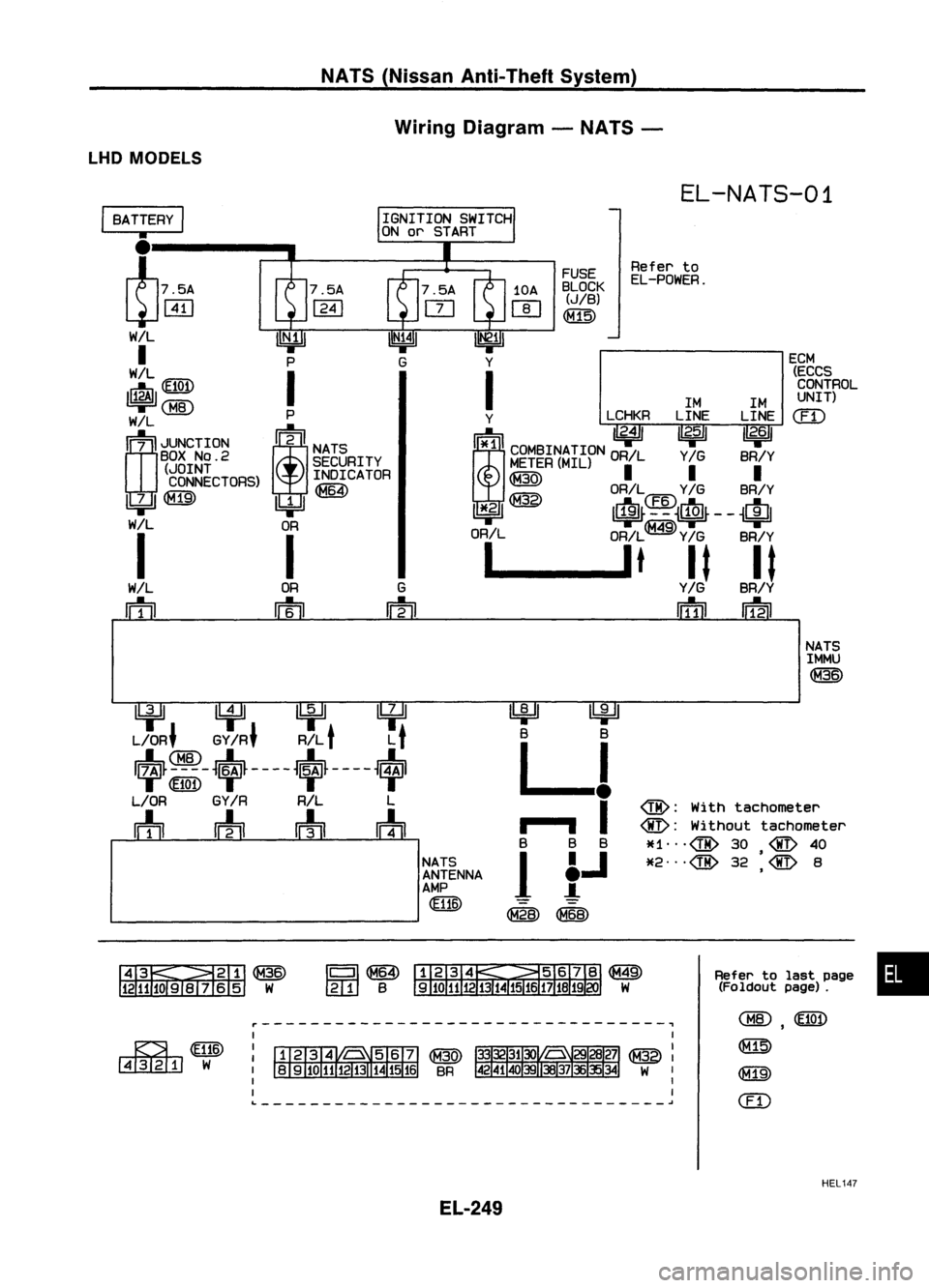
NATS(Nissan Anti-Theft System)
Wiring Diagram -NATS -
LHD MODELS
EL-NATS-01
ECM(ECCSCONTROL
UNIT)
em
Refer
to
EL-POWER.
FUSE
BLOCK
(JIB)
~
1M1M
Y LCHKRLINELINE
!i*1ll
"2.4/
I~ I 1/
2•6
11
i
COMBINATION ORILY
IG
BR/Y
M~~ER(MIL)
II I
~ OR/L
Y/G
BR/Y
11*.21 ~ It~~4~~~$~--
~Ifll
OR/L OR/L
Y/G
BR/Y
1 __
lt
It It
Y/G
BR/Y
IiTIil
IDil
G
m
OR
m
I
BATTERY
I
•
l75A
~WJ
W/L
I
WIL
~(fI@
~
rn;
I
JUNCTION
BOX
NO.2
(JOINT
CONNECTORS)
~
I
WIL
rn
NATSIMMU
~
~ lifll
U:¥~
L/OR' GY
IR'
R/L
t
L
t
~~-~~~----~~~----~
L/OR GY
IR
R/L L
m
wh
rrh
m
NATSANTENNA
AMP
~
~
B B
LJ
..
,- .., I
B BB
1
f.J
~~
@:
With tachometer
@:
Without tachometer
*1",@ 30
@
40
•
*2",@ 32
@
8
,
&~~
1211JOSIV 65 W
Refer
tolast page •
(Foldout page).
~WID
~W
r---------------------------------~
L ~
,
~
@])
em
HEL147
EL-249
Page 622 of 1701
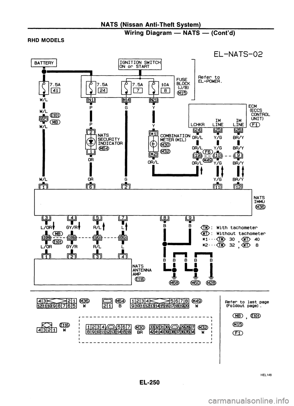
NATS(Nissan Anti-Theft System)
Wiring Diagram -NATS -(Cont'd)
RHO MODELS
EL-NATS-02
ECM
(ECCS
CONTROL
UNIT)
em
Refer
to
EL-POWER.
FUSE
BLOCK (JIB)
~
1M1M
Y LCHKRLINELINE
mITn 11
2•4
11
2•5
I 11
2•6
1
i
~~~~~~~iCPN OR,LY.GBR,Y
~ OR/L
Y/G
BR/Y
11*.21
@
1$~~4~~$~--
~cIJl
OR/L OR/L
Y/G
BR/Y
1 __
lt
It It
Y/G
BR/Y
riTIil ~
G
rn
OR
rrn
W/L
rn
I
BATTERY
I
•
17.5A
~ffi)
WIL
I
W/L
tr.i\i\
db~
I~I
WIL
NATS
1MMU
@
UfJ ~
LlfU~
L/OR~ GYIR~ R/L
t
L
t
+
ii:~-
i+~ -- - -i+~ -- --
+
L/OR GY
IR
RIL L
m
rrfn
rrh
m
NATSANTENNA
AMP
@ID ~
~
B B
@:
With tachometer
1-.J
@:
Without tachometer
*1' ..@30 @40
•
*2"'@ 32
@
8
I
...-w -,--; ·
B B BB B
Li Li
J
(868)
<8W~
Refertolast page
(Foldout page).
~WID
I:illImJ
W
I
I
I
I
I
I
L
~
HEL148
EL-250
Page 623 of 1701
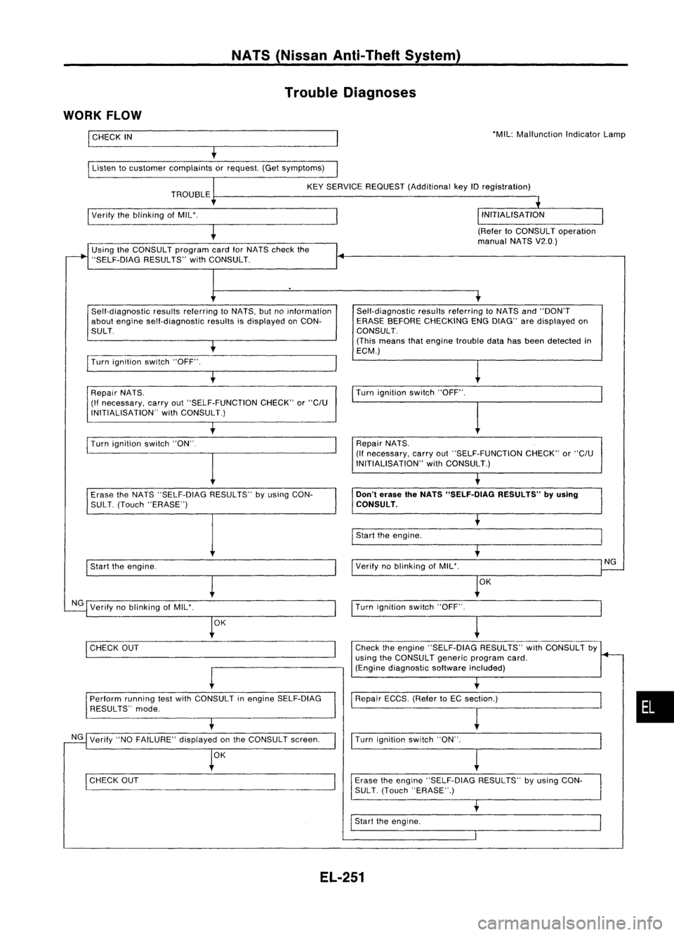
NATS(Nissan Anti-Theft System)
Trouble Diagnoses
WORK FLOW
I
CHECK
IN
Listen tocustomer complaints orrequest. (Getsymptoms) 'MIL:
Malfunction IndicatorLamp
KEY SERVICE REQUEST (Additional keyIDregistration)
TROUBLE
I
Verify theblinking ofMIL'.
(RefertoCONSULT operation
manual NATSV2.0.)
Using theCONSULT programcardforNATS check the
"SELF-DiAG RESULTS"withCONSULT.
Self-diagnostic resultsreferring toNATS, butnoinformation
about engine self-diagnostic resultsisdisplayed onCON-
SULT.
I
Turn ignition switch"OFF".
t
Repair NATS.
(If necessary, carryout"SELF-FUNCTION CHECK"or
"C/U
INITIALISATION" withCONSULT.) Self-diagnostic
resultsreferring toNATS and"DON'T
ERASE BEFORE CHECKING ENGDIAG" aredisplayed on
CONSULT.
(This means thatengine trouble datahasbeen detected in
ECM.)
Turn ignition switch"OFF".
I
Turn ignition switch"ON".
I
Repair
NATS.
(If necessary, carryout"SELF-FUNCTION CHECK"or
"C/U
INITIALISATION" withCONSULT.)
Erase theNATS "SELF-DIAG RESULTS"byusing CON-
SUL T.(Touch "ERASE")
I
Start theengine.
NG Verify noblinking ofMIL'.
OK
I
CHECK OUT
-
Perform runningtestwith CONSULT inengine SELF-DiAG
RESULTS" mode.
NG Verify "NOFAILURE" displayedonthe CONSULT screen.
OK
I
CHECK OUT
Don't
erase theNATS "SELF.DlAG RESULTS"byusing
CONSULT.
I
Start theengine.
Verify noblinking ofMIL'.
OK
I
Turn ignition switch"OFF".
~
Check theengine "SELF-DiAG RESULTS"withCONSULT by
using theCONSULT genericprogram card.
(Engine diagnostic softwareincluded)
Repair ECCS.(RefertoEC section.)
I
Turn ignition switch"ON".
Erase theengine "SELF-DIAG RESULTS"byusing CON-
SUL T.(Touch "ERASE".)
I
Start theengine.
NG
•
EL-251
Page 624 of 1701
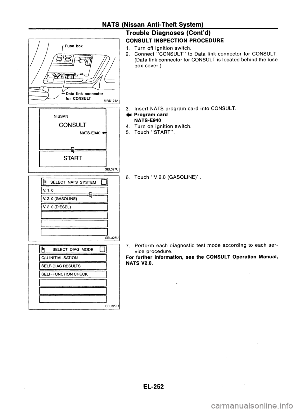
3.Insert NATSprogram cardintoCONSULT.
+:
Program card
NATS-E940
4. Turn onignition switch.
5. Touch "START".
NISSAN NATS
(Nissan Anti-Theft System)
Trouble Diagnoses (Cont'd)
CONSULT INSPECTION PROCEDURE
1. Turn offignition switch.
2. Connect "CONSULT" toData linkconnector forCONSULT.
(Data linkconnector forCONSULT islocated behindthefuse
box cover.)
CONSULT
~====Iij-=:J
START
I
SEL327U
~ SELECT NATSSYSTEM
0
I
6.
Touch "V.2.0(GASOLINE)".
V.1.0
V. 2.0(GASOLINE)
V. 2.0(DIESEL)
SEL328U
~ SELECT DIAGMODE
D
c/u INITIALISATION
SELF-DIAG RESULTS
SELF-FUNCTION CHECK
7.
Perform eachdiagnostic testmode according toeach ser-
vice procedure.
For further information, seetheCONSULT OperationManual,
NATS V2.0.
SEL329U
EL-252
Page 625 of 1701
NATS(Nissan Anti-Theft System)
Trouble Diagnoses (Cont'd)
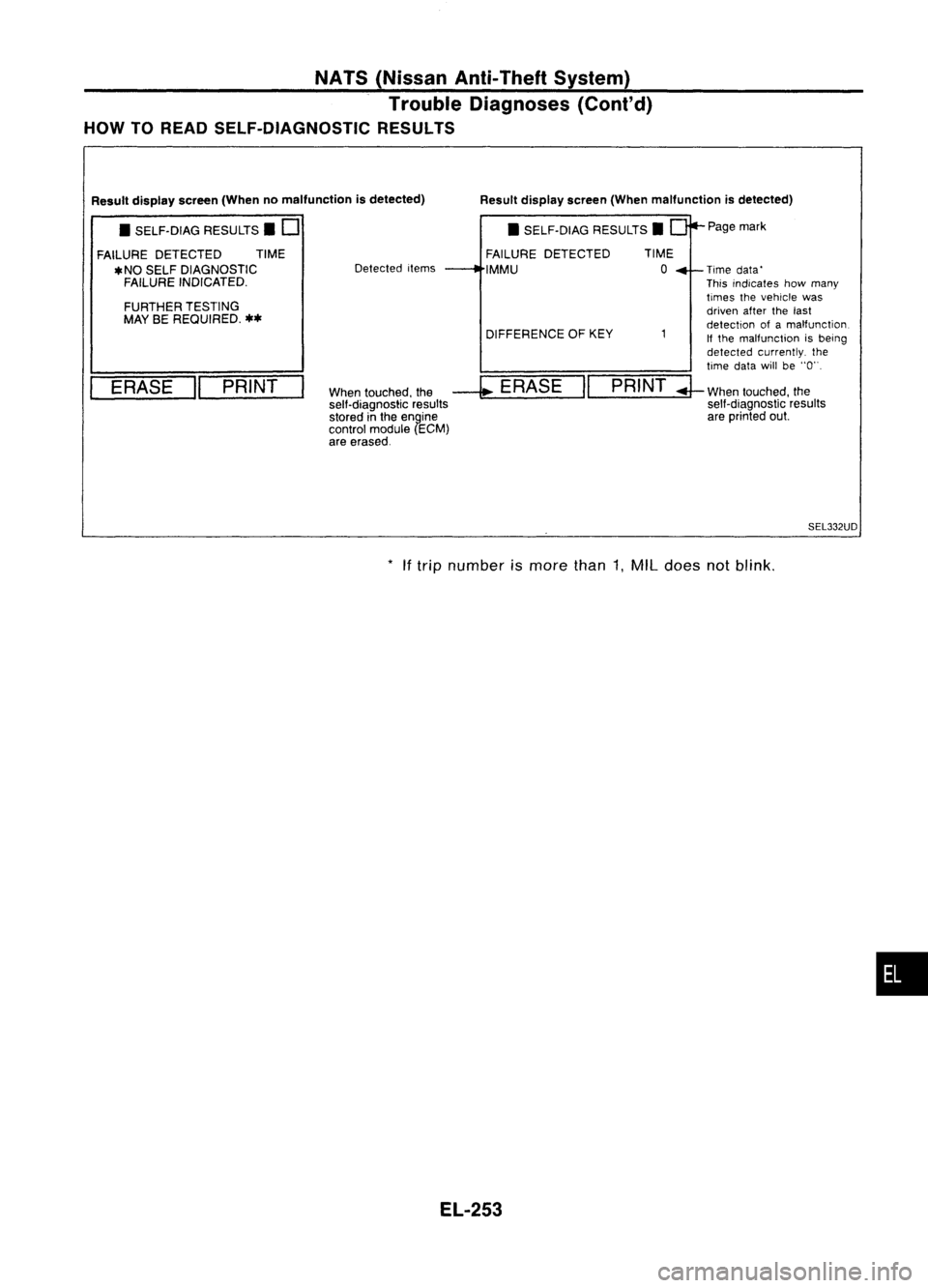
HOW TOREAD SELF-DIAGNOSTIC RESULTS
Resultdisplay screen(Whenmalfunction isdetected)
When touched, the
--l;
ERASE "PRINT
sell-diagnostic results
stored inthe engine
control module (ECM)
are erased. Page
mark
Time data'
This indicates howmany
times thevehicle was
driven afterthelast
detection ofamalfunction
If the malfunction isbeing
detected currently. the
time datawillbe"0".
;J-
When touched, the
self-diagnostic results
are printed out.
DIFFERENCE
OFKEY
•
SELF-DIAG RESULTS.
FAILURE DETECTED
IMMU
Detected
items
FURTHER TESTING
MAY BEREQUIRED.
**
ERASE "PRINT
Result
display screen(Whennomalfunction isdetected)
• SELF-DIAG RESULTS. D
FAILURE DETECTED TIME
*NO SELF DIAGNOSTIC
FAILURE INDICATED.
SEL332UD
*
Iftrip number ismore than1,MIL does notblink .
•
EL-253
Page 626 of 1701
NATS(Nissan Anti-Theft System)
Trouble Diagnoses (Cont'd)
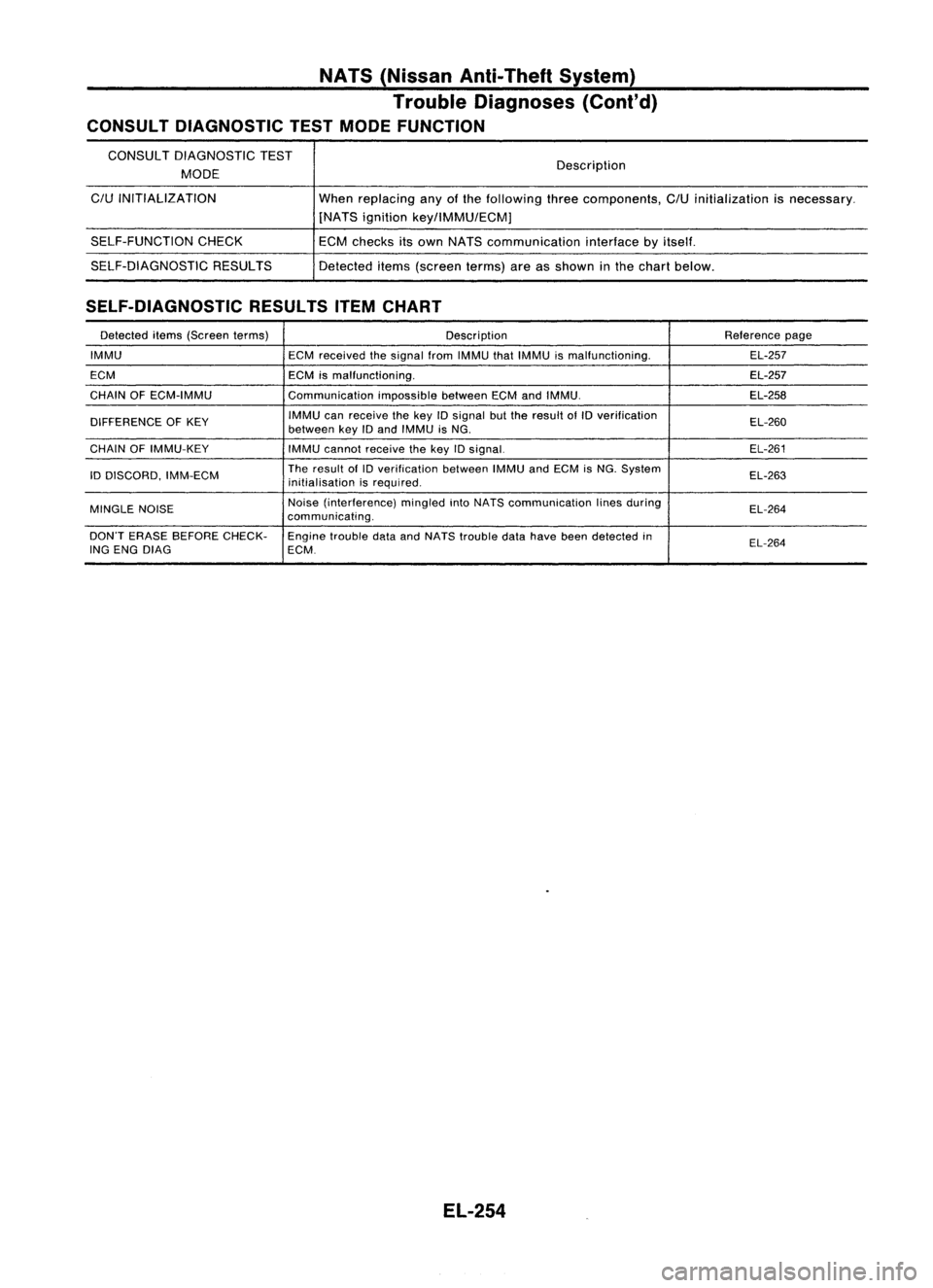
CONSULT DIAGNOSTIC TESTMODE FUNCTION
CONSULT DIAGNOSTIC TEST
MODE
C/U
INITIALIZATION
SELF-FUNCTION CHECK
SELF-DIAGNOSTIC RESULTS Description
When replacing anyofthe following threecomponents,
C/U
initialization isnecessary.
[NATS ignition key/lMMU/ECMj
ECM checks itsown NATS communication interfacebyitself.
Detected items(screen terms)areasshown inthe chart below.
SELF-DIAGNOSTIC RESULTSITEMCHART
Detected items(Screen terms) Description Reference
page
IMMU ECMreceived thesignal fromIMMU thatIMMU ismalfunctioning. EL-257
ECM ECMismalfunctioning. EL-257
CHAIN OFECM-IMMU CommunicationimpossiblebetweenECMandIMMU. EL-258
DIFFERENCE OFKEY IMMU
canreceive thekey
10
signal butthe result ofID verification
EL-260
between keyIDand IMMU isNG.
CHAIN OFIMMU-KEY
IMMUcannot receive thekey IDsignal. EL-261
ID DISCORD, IMM-ECM The
result of
10
verification betweenIMMUandECM isNG. System
EL-263
initialisation isrequired.
MINGLE NOISE Noise
(interference) mingledintoNATS communication linesduring
EL-264
communicating.
DON'T ERASE BEFORE CHECK-
Enginetrouble dataandNATS trouble datahave beendetected in
EL-264
ING ENG DIAG ECM.
EL-254
Page 627 of 1701
NATS(Nissan Anti-Theft System)
Trouble Diagnoses (Cont'd)
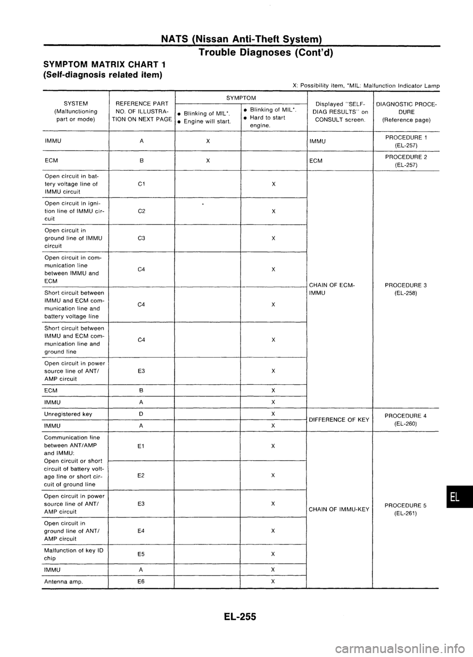
SYMPTOM MATRIXCHART1
(Self-diagnosis relateditem)
X:Possibility item.'MIL: Malfunction IndicatorLamp
SYMPTOM
SYSTEM REFERENCEPART
Displayed"SELF-
DIAGNOSTIC PROCE-
(Malfunctioning NO.OFILLUSTRA-
•Blinking ofMIL'. •
Blinking ofMIL'.
DIAGRESULTS" on
DURE
part ormode) TIONONNEXT PAGE
•Engine willstart. •
Hard tostart
CONSULTscreen.
(Referencepage)
engine.
IMMU A
X IMMUPROCEDURE
1
(EL-257)
ECM BX
ECMPROCEDURE
2
(EL-257)
Open circuit inbat-
tery voltage lineof C1
X
IMMU circuit
Open circuit inigni-
.
tion lineofIMMU cir- C2
X
cuit
Open circuit in
ground lineofIMMU
C3 X
circuit
Open circuit incom-
munication line
C4
X
between IMMUand
ECM CHAINOFECM-
PROCEDURE3
Short circuit between IMMU
(EL-258)
IMMU andECM com-
C4
X
munication lineand
battery voltage line
Short circuit between
IMMU andECM com-
C4 X
munication lineand
ground line
Open circuit inpower
source lineofANTI E3
X
AMP circuit
ECM B X
IMMU A
X
Unregistered key 0 X
PROCEDURE4
DIFFERENCE OFKEY
IMMU A
X
(EL-260)
Communication line
between ANT
I
AMP
E1
X
and IMMU:
Open circuit orshort
circuit ofbattery volt-
age lineorshort cir- E2
X
cuit ofground line
Open circuit inpower
source lineofANTI E3
X
PROCEDURE5
AMP circuit CHAIN
OFIMMU-KEY
(EL-261)
Open circuit in
ground lineofANTI E4
X
AMP circuit
Malfunction ofkey 10
E5 X
chip
IMMU A
X
Antenna amp. E6
X
EL-255
•
Page 628 of 1701
NATS(Nissan Anti-Theft System)
Trouble Diagnoses (Cont'd)
SYMPTOM
SYSTEM REFERENCEPART Displayed"SELF- DIAGNOSTIC
PROCE-
(Malfunctioning NO.OFILLUSTRA-
•Blinking ofMIL*. •
Blinking ofMIL *.
DIAGRESULTS" on DURE
part ormode)
TIONONNEXT PAGE
•Engine willstart. •
Hard tostart
CONSULTscreen. (Reference
page)
engine.
System initialisation
has notyetbeen
F X
10
DISCORD, IMM- PROCEDURE 6
completed. ECM(EL-263)
ECM F X
Noise interference in
XMINGLE
NOISE PROCEDURE
7
communication line (EL-264)
Engine trouble data
DON'TERASE
and NATS trouble
BEFORECHECKING WORK
FLOW
data have been X
X
(EL-251)
detected inECM ENG
DIAG
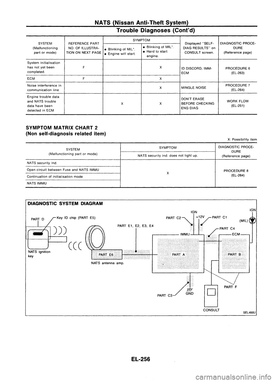
SYMPTOM MATRIXCHART2
(Non self-diagnosis relateditem)
X:Possibility item
SYSTEM SYMPTOM
DIAGNOSTIC
PROCE-
(Malfunctioning partormode) DURE
NATS security indodoes notlight up.
(Referencepage)
NATS security indo
Open circuit between FuseandNATS IMMU
PROCEDURE8
X (EL-264)
Continuation ofinitialisation mode
NATS IMMU
DIAGNOSTIC SYSTEMDIAGRAM
NATS antenna amp.
PART
0 Key10chip (PART E5)
i-------
L---
--j)))
:
.
, ,
I~ .'
(((
NATS ignition
key
PART
E1,E2,E3, E4 IGN
PART C2~ +1./PART C1(MIL)
PART C4
ECM
..
........
................
:'
.......
PART F
D
IGN
EL-256
CONSULT
SEL466U
Page 629 of 1701
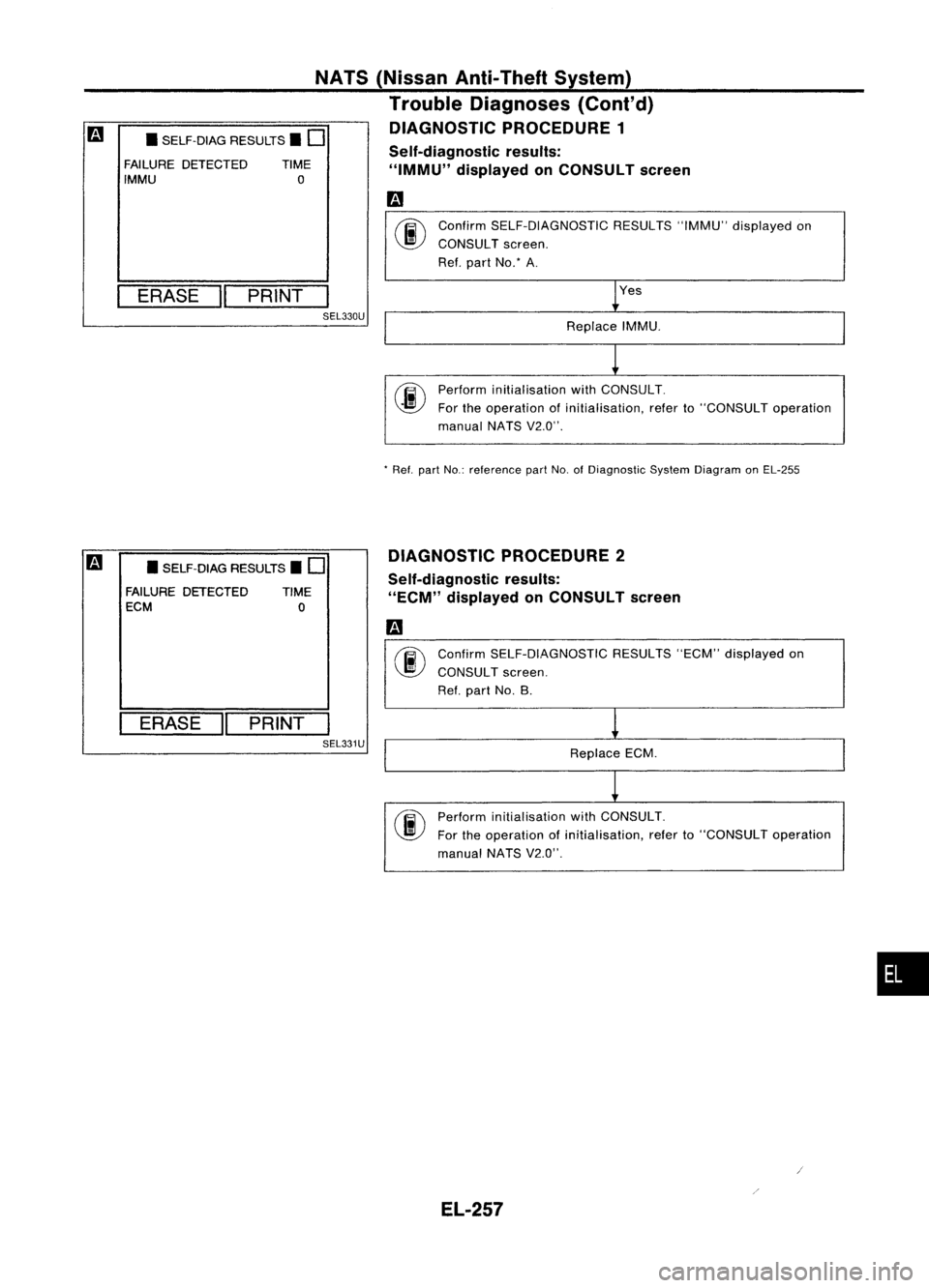
Yes
Confirm
SELF-DIAGNOSTIC RESULTS"IMMU"displayed on
CONSULT screen.
Ref. part No: A.
Replace IMMU.
NATS
(Nissan Anti-Theft System)
Trouble Diagnoses (Cont'd)
DIAGNOSTIC PROCEDURE 1
Self-diagnostic results:
"IMMU" displayed onCONSULT screen
m
•SELF-DIAG RESULTS.
0
FAILURE DETECTED TIME
IMMU
0
I
ERASE
II
PRINT
I
SEL330U
Performinitialisation withCONSULT.
For theoperation ofinitialisation, referto"CONSULT operation
manual NATSV2.0".
*
Ref. partNo.:reference partNo.ofDiagnostic SystemDiagram onEL-255
m
•SELF-DIAG RESULTS.
0
FAILURE DETECTED TIME
ECM
0
I
ERASE
II
PRINT
I
SEL331U DIAGNOSTIC
PROCEDURE 2
Self-diagnostic results:
"ECM" displayed onCONSULT screen
Confirm SELF-DIAGNOSTIC RESULTS"ECM"displayed on
CONSULT screen.
Ref. part No.B.
Replace ECM.
Perform initialisation withCONSULT.
For theoperation ofinitialisation, referto"CONSULT operation
manual NATSV2.0".
•
EL-257
Page 630 of 1701
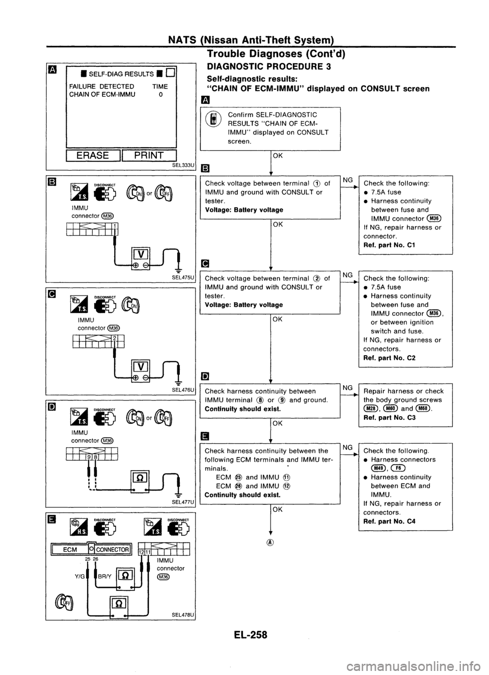
•SELF-DIAG RESULTS.
0
FAILURE DETECTED
CHAIN OFECM-IMMU TIME
o
NATS
(Nissan Anti-Theft System)
Trouble Diagnoses (Cont'd)
DIAGNOSTIC PROCEDURE3
Self-diagnostic results:
"CHAIN OFECM-IMMU" displayedonCONSULT screen
m
ERASE
II
PRINT
I
SEL333U
IMMU
connector@
EEFf
I
fEill
SEL475U
IMMU
connector@
EEFf,11lE
SEL476U
IMMU
connector@
m
'--Ulsl
SEL477U
Ii
~i5 ~i5
II
ECM
El'CONNECTORII WilfEB
~~ IMMU
connector
Y/G
BRIY
[fiJ
@
~ fQj
SEL478U
00
Confirm
SELF-DIAGNOSTIC
RESULTS "CHAINOFECM-
IMMU" displayed onCONSULT
screen.
OK
Ii)
Check voltage between terminal
G)
of NG
Check thefollowing:
IMMU andground withCONSULTor
1----+
•7.5A fuse
tester. •
Harness continuity
Voltage: Batteryvoltage between
fuseand
OK IMMU
connector
@
If
NG, repair harness or
connector. Ref. part No.C1
~
Check voltage between terminal
@
of NG
Check thefollowing:
IMMU andground withCONSULTor
1----+
•7.5A fuse
tester. •Harness continuity
Voltage: Batteryvoltage betweenfuseand
OK IMMU
connector
@,
or between ignition
switch andfuse.
If NG, repair harness or
connectors. Ref. part No.C2
I!]
Check harness continuity between NG
Repair harness orcheck
IMMU terminal
CID
or
@
and ground.
r----.-
thebody ground screws
Continuity shouldexist. @,@and@!).
OK Ref.
part No.C3
Ii
Check harness continuity betweentheNG
Check thefollowing.
following ECMterminals andIMMU ter-
1----+
•Harness connectors
minals.
.
@,QD
ECM
@
and IMMU
@
•
Harness continuity
ECM
@
and IMMU
@
between
ECMand
Continuity shouldexist. IMMU.
OK If
NG, repair harness or
connectors.
Ref. part No.C4
EL-258