NISSAN ALMERA N15 1995 Service Manual
Manufacturer: NISSAN, Model Year: 1995, Model line: ALMERA N15, Model: NISSAN ALMERA N15 1995Pages: 1701, PDF Size: 82.27 MB
Page 631 of 1701
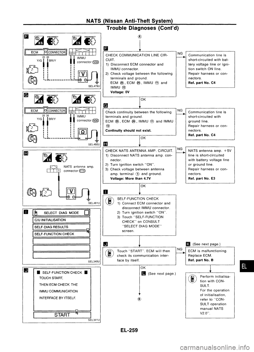
NATS(Nissan Anti-Theft System)
Trouble Diagnoses (Cont'd)
II
ECM
~CONNECTORII
~1=rEE
2526
11
IMMU
Y/G'
'BRIY ,, connector
@
~:: ::5JlM
I
I II
~ II II
~ L.l.................. _':"
SEL479U CHECK
COMMUNICATION LINECIR-
CUIT. 1) Disconnect ECMconnector and
IMMU connector.
2) Check voltage between thefollowing
terminals andground.
ECM
@.
ECM
@l,
IMMU @and
IMMU @
Voltage: OV
Ii
Ii
@
1
NG
---.. Communication
lineis
short-circuited withbat-
tery voltage lineorigni-
tion switch ONline.
Repair harness orcon-
nectors.
Ref. part No.C4
OK
Check continuity betweenthefollowing
terminals andground.
ECM
@,
ECM
@.
IMMU @and IMMU
@
Continuity shouldnotexist.
II
ECM
~
CONNECTOR
II~ 11133
2526
11
IMMU
Y/G'
'BRIY ,, connector
@
J0., "
~:: ::19JlO
~ II II
~ ~. .l.._............... ':"
SEL480U
III
OK Communication
lineis
short-circuited with
ground line.
Repair harness orcon-
nectors.
Ref. pari No.C4
III
R3LNATSantenna amp.
ITIID
connector
@ill)
CHECK
NATSANTENNA AMP.CIRCUIT.
1) Disconnect NATSantenna amp.con-
nector.
2) Turn ignition switch"ON".
3) Check voltage between antenna
amp. terminal
G)
and ground.
Voltage: Morethan4.7V NG
~ NATS
antenna amp.+5V
line isshort-circuited
with battery voltage line
or ground line.
Repair harness orcon-
nectors.
Ref. part No.E3
OK
SEL481U
SEL340U
•
Perform
initialisa-
tion with CON-
SULT. For theoperation
of initialisation,
refer to"CON-
SUL Toperation
manual NATS
V2.0".
II
(See nextpage.)
~ ECMismalfunctioning.
Replace ECM.
Ref. part No.B
screen.
OK
m
(See nextpage.)
SELF-FUNCTION
CHECK
1) Connect ECMconnector and
disconnect IMMUconnector.
2) Turn ignition switch"ON".
3) Touch "SELF-FUNCTION
CHECK" onCONSULT
"SELECT DIAGMODE"
Touch "START". ECMwillthen
check itscommunication inter-
face byitself.
o
@
START ij~
SEL341U
•
SELF-FUNCTION CHECK•
TOUCH START,
THEN ECMCHECK THE
IMMU COMMUNiCATION
INTERFACE BYITSELF.
~
SELECT DIAGMODE
C/U INITIALISATION
SELF-DIAG RESULTS
SELF-FUNCTION CHECK
01
I
III
====1
I
I
o
EL-259
Page 632 of 1701
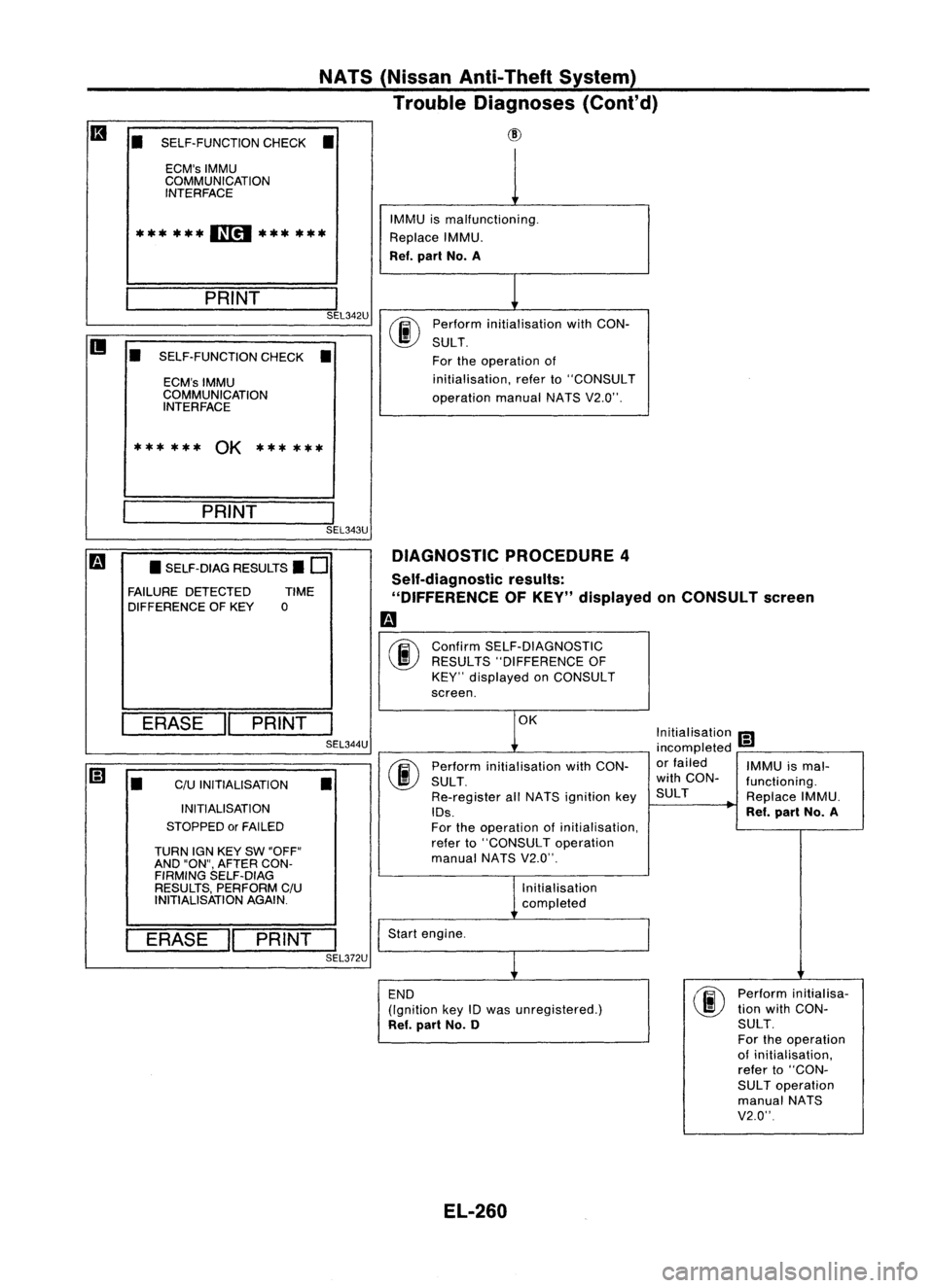
NATS(Nissan Anti-Theft System)
Trouble Diagnoses (Cont'd)
• SELF-FUNCTION CHECK•
ECM's IMMU
COMMUNICATION INTERFACE
II
***
***
11[!1
******
___ P_R_IN_T
I
SEL342U
• SELF-FUNCTION CHECK•
ECM's IMMU
COMMUNICATION INTERFACE
******
OK
******
___ P_RI_N_T '
SEL343U IMMU
ismalfunctioning.
Replace IMMU.
Ref. part No.A
00
Perform
initialisation withCON-
SULT.
For theoperation of
initialisation, referto"CONSULT
operation manualNATSV2.0".
m
•SELF-DIAG RESULTS.
0
FAILURE DETECTED TIME
DIFFERENCE OFKEY
0
I
ERASE
"
PRINT
I
SEL344U
ERASE
II
PRINT
I
SEL372U
•
C/U
INITIALISATION
INITIALISATION
STOPPED orFAILED
TURN IGNKEY SW"OFF"
AND "ON" AFTER CON-
FIRMING SELF-DIAG
RESULTS, PERFORM C/U
INITIALISATION AGAIN.
•
DIAGNOSTIC
PROCEDURE 4
Self-diagnostic results:
"DIFFERENCE OFKEY" displayed onCONSULT screen
m
00
Confirm
SELF-DIAGNOSTIC
RESULTS "DIFFERENCE OF
KEY" displayed onCONSULT
screen.
t
K
Initialisation
I!J
incompleted •
00
Perform
initialisation withCON- or
failed
IMMUismal-
SULT . with
CON-
functioning.
Re-register allNATS ignition keySULT
ReplaceIMMU.
IDs. Ref.
part No.A
For theoperation ofinitialisation,
refer to"CONSULT operation
manual NATSV2.0".
l,nitialisation completed
Start engine.
~
END
00
Perform
initial isa-
(Ignition keyIDwas unregistered.) tion
with CON-
Ref. part No.0 SULT.
For theoperation
of initialisation,
refer to"CON-
SUL Toperation
manual NATS
V2.0"
EL-260
Page 633 of 1701
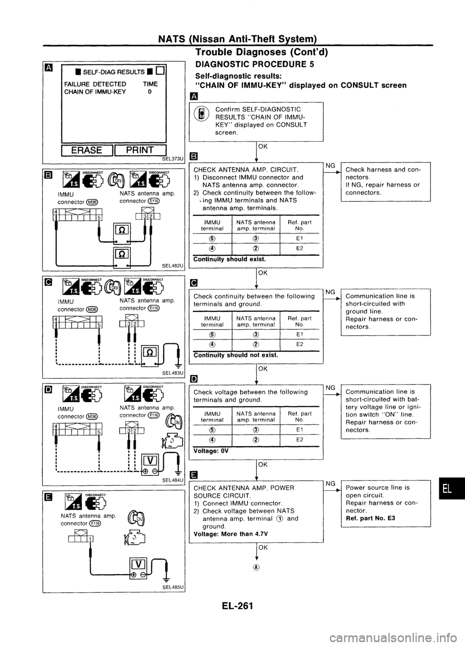
ConfirmSELF-DIAGNOSTIC
RESULTS "CHAINOFIMMU-
KEY" displayed onCONSULT
screen.
Self-diagnostic
results:
"CHAIN OFIMMU-KEY" displayedonCONSULT screen
m
00
NATS
(Nissan Anti-Theft System)
Trouble Diagnoses (Cont'd)
DIAGNOSTIC PROCEDURE 5
• SELF-DIAG RESULTS.
0
FAILURE DETECTED TIME
CHAIN OFIMMU-KEY 0
•
Communication
lineis
short-circuited withbat-
tery voltage lineorigni-
tion switch "ON"line.
Repair harness orcon-
nectors.
Power source lineis
open circuit.
Repair harness orcon-
nector.
Ref. part No.E3
Communication
lineis
short-circuited with
ground line.
Repair harness orcon-
nectors.
Check
harness andcon-
nectors.
If NG, repair harness or
connectors.
NG
NG
NG
NG
IMMU NAT8
antenna Ref.part
terminal amp.
terminal No.
@
@
E1
@
~)
E2
IMMU
NA
T8 antenna Ref.part
terminal amp.terminal No.
@
@
E1
@
~
E2
IMMU NAT8
antenna Ref.part
terminal amp.
terminal No.
@
@
E1
@
~
E2
OK
CHECK
ANTENNA AMP.POWER
SOURCE CIRCUIT.
1) Connect IMMUconnector.
2) Check voltage between NATS
antenna amp.terminal G)and
ground.
Voltage: Morethan4.7V
Check
voltage between thefollowing
terminals andground.
Continuity
shouldnotexist.
Check
continuity betweenthefollowing
terminals andground.
CHECK
ANTENNA AMP.CIRCUIT.
1) Disconnect IMMUconnector and
NATS antenna amp.connector.
2) Check continuity betweenthefollow-
• ing IMMU terminals andNATS
antenna amp.terminals.
Voltage: OV
Continuity
shouldexist.
SEL482U
NATS antenna amp.
connector~
~~i5
NATS antenna amp.
connector~
IMMU
connector@
SEL483U
~,34=@
~
: ,I~~
I
I III
[ill
I III ~..
I III
I III
I ,•
'
__
.-
..
-.
__
~
ERASE
"PRINT
I
1:1.
SEL373U W
NATS antenna amp.
connector~
IMMU
NATSantenna amp.
connector
@
connector~~
r=am
T6
: t::~
I I"
flTl
, II'L!.-J
I II•
, II,
.------_
....
----_........
-
~
SEL484U
IMMU
connector@
ma,
~~fJ
[ill
SEL485U EL-261
Page 634 of 1701
Ii
1
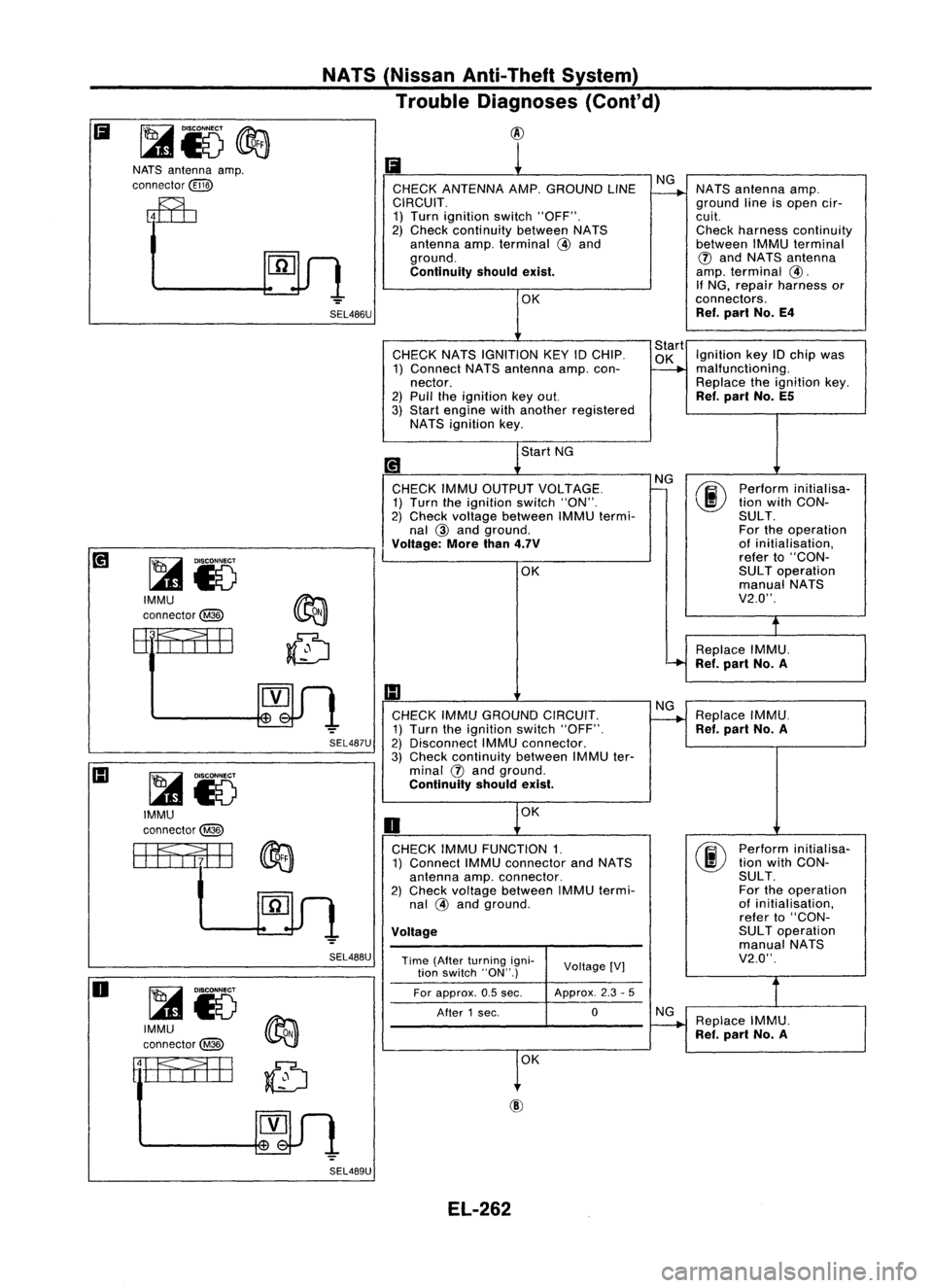
CHECK ANTENNA AMP.GROUND LINENG
~
NATS
antenna amp.
CIRCUIT. groundlineisopen cir-
1) Turn ignition switch"OFF". cuit.
2) Check continuity betweenNATS Checkharness continuity
antenna amp.terminal
@
and betweenIMMUterminal
ground.
(J)
and NATS antenna
Continuity shouldexist.
amp.
terminal
@.
If NG, repair harness or
OK connectors.
Ref. part No.E4
CHECK NATSIGNITION KEY
10
CHIP. Start
Ignition key
10
chip was
1) Connect NATSantenna amp.con-
~
malfunction
i
ng.
nector. Replacetheignition key.
2) Pull theignition keyout.
Ref.
part No.E5
3) Start engine withanother registered
NATS ignition key.
Start NG
[!1
NG
00
Perform
initialisa-
CHECK IMMUOUTPUT VOLTAGE.
-
1) Turn theignition switch"ON". tion
with CON-
2) Check voltage between IMMUtermi- SULT.
nal
@
and ground. Fortheoperation
Voltage: Morethan4.7V
of
initialisation,
refer to"CON-
OK SUL
Toperation
manual NATS
V2.0".
t
Replace IMMU.
'-+
Ref.part No.A
1:1
CHECK IMMUGROUND CIRCUIT. NG
Replace IMMU.
~
1) Turn theignition switch"OFF".
Ref.part No.A
2) Disconnect IMMUconnector.
3) Check continuity betweenIMMUter-
minal
(J)
and ground.
Continuity shouldexist.
OK
0
CHECK IMMUFUNCTION 1.
00
Perform
initialisa-
1) Connect IMMUconnector andNATS tion
with CON-
antenna amp.connector. SULT.
2) Check voltage between IMMUtermi- For
theoperation
nal
@
and ground. of
initialisation,
refer to"CON-
Voltage
SUL
Toperation
manual NATS
Time (After turning igni-
VoltageIV] V2.0".
tion switch "ON".)
For approx. 0.5sec. Approx.
2.3-5
After 1sec. 0
NG
Replace IMMU.
~
Ref.part No.A
1
0K
SEL486U
SEL488U
SEL487U
NATS
(Nissan Anti-Theft System)
Trouble Diagnoses (Cont'd)
@
~i5
IMMU
connector@
~i5
IMMU
connector@
ffitflfEB
NATS
antenna amp.
connector
@ID
~i5
IMMU
connector@
rtfa;EB
Ii
o
SEL489UEL-262
Page 635 of 1701
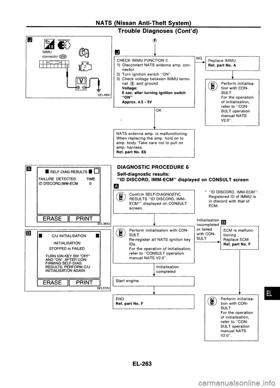
SEL490U
IMMU
connector@
NATS
(Nissan Anti-Theft System)
Trouble Diagnoses (Cont'd)
CID
II
1
CHECK IMMUFUNCTION 2. NG
Replace IMMU.
1) Disconnect NATSantenna amp.con-
r---+
Ref.part No.A
nector.
1
2)
Turn ignition switch"ON".
3) Check voltage between IMMUtermi-
nal
@
and ground.
00
Perform
initialisa-
Voltage: tion
with CON-
6 sec. after turning ignition switch SULT.
"ON" Fortheoperation
Approx. 4.5-5V of
initialisation,
refer to"CON-
OK SULToperation
manual NATS
V2.0".
NATS antenna amp.ismalfunctioning.
When replacing theamp. holdonto
amp. body. Takecarenottopull on
amp. harness.
Ref. part No.E6
DIAGNOSTIC PROCEDURE6
*"10 DISCORD, IMM-ECM":
Registered IDofIMMU is
in discord withthatof
ECM.
Confirm
SELF-DIAGNOSTIC
RESULTS "10DISCORD, IMM-
ECM*" displayed onCONSULT
screen.
Self-diagnostic
results:
"ID DISCORD, IMM-ECM" displayedonCONSULT screen
m
00
•
SELF-DIAG RESULTS.
0
FAILURE DETECTED TIME
ID DISCORD,IMM-ECM 0
ERASE
II
PRINT
I
SEL383U
[;]
•
C/U
INITIALISATION
•
INITIALISATION
STOPPED orFAILED
TURN IGNKEY SW"OFF"
AND "ON", AFTER CON-
FIRMING SELF-DIAG
RESULTS, PERFORM C/U
INITIALISATION AGAIN.
ERASE
II
PRINT
I
SEL372U Perform
initialisation withCON-
SULT .
Re-register allNATS ignition key
IDs.
For theoperation ofinitialisation,
refer to"CONSULT operation
manual NATSV2.0".
Initialisation
completed
Start engine.
END
Ref. part No.F Initialisation
[;]
incompleted -
or failed ECMismalfunc-
with CON- tioning.
SUL T ReplaceECM.
Ref. part No.F
Perform initialisa-
tion with CON-
SULT.
For theoperation
of initialisation,
refer to"CON-
SUL Toperation
manual NATS
V2.0".
•
EL-263
Page 636 of 1701
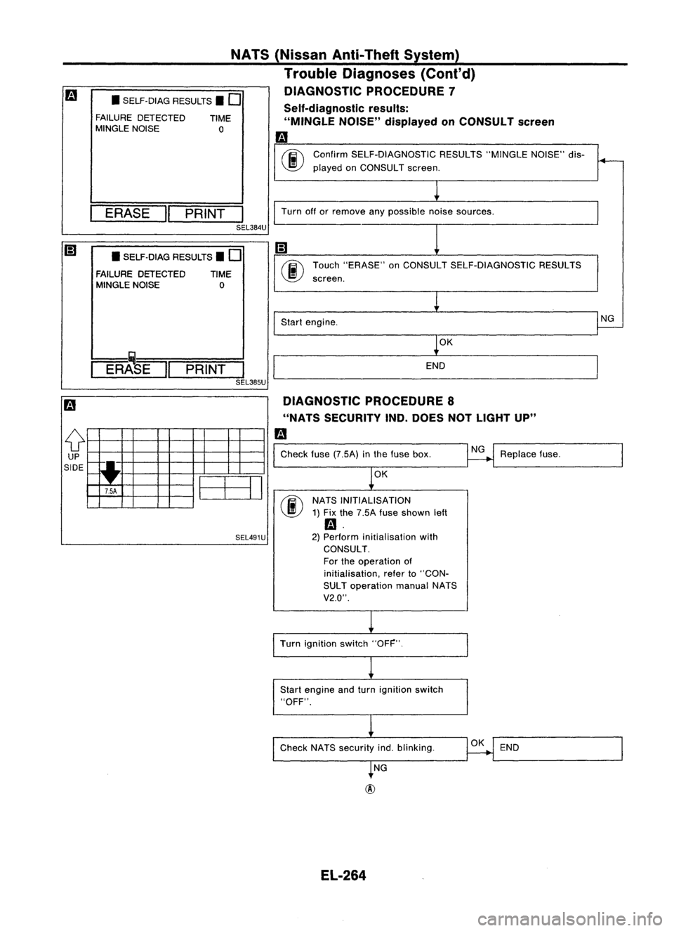
Self-diagnosticresults:
"MINGLE NOISE"displayed onCONSULT screen
m
T
Confirm SELF-DIAGNOSTIC RESULTS"MINGLENOISE"dis-
~ played onCONSULT screen.
NATS
(Nissan Anti-Theft System)
Trouble Diagnoses (Cont'd)
DIAGNOSTIC PROCEDURE 7
• SELF.DIAG RESULTS.
0
FAILURE DETECTED TIME
MINGLE NOISE 0
ERASE
II
PRINT
I
Turnofforremove anypossible noisesources.
SEL384U
• SELF.DIAG RESULTS.
0
FAILURE DETECTED TIME
MINGLE NOISE 0 Touch
"ERASE" onCONSULT SELF-DIAGNOSTIC RESULTS
screen.
ER~I PRINT
I
SEL385U
Start
engine.
OK
END
NG
DIAGNOSTIC PROCEDURE8
"NATS SECURITY IND.DOES NOTLIGHT UP"
m
o
UP
SIDE I~
....
EE3J
7.5A
SEL491U
Check
fuse(7.5A) inthe fuse box.
OK
NATS INITIALISATION
1) Fix the 7.5A fuseshown left
m.
2) Perform initialisation with
CONSULT.
For theoperation of
initialisation, referto"CON-
SUL Toperation manualNATS
V2.0".
NG
Replace fuse.
Turn ignition switch"OFF".
Start engine andturn ignition switch
"OFF".
Check NATSsecurity indoblinking.
OK
END
NG
EL-264
Page 637 of 1701
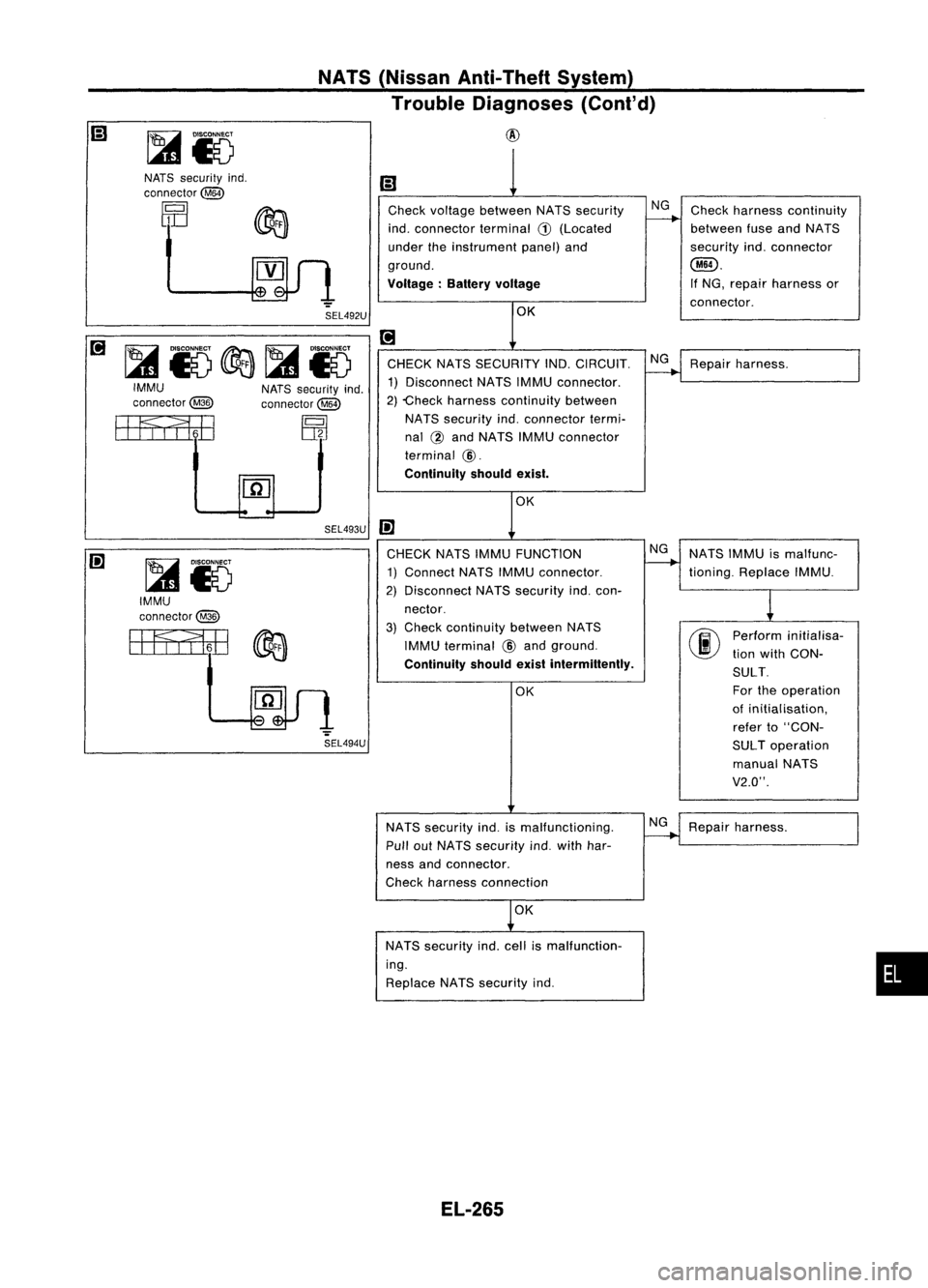
NATS(Nissan Anti-Theft System)
Trouble Diagnoses (Cont'd)
@
•
Ii)
Check voltage between NATSsecurity NG
Check harness continuity
indo connector terminal
G)
(Located
f------+
between fuseandNATS
under theinstrument panel)and securityindoconnector
ground.
@).
Voltage: Batteryvoltage
If
NG, repair harness or
connector .
OK
[!]
CHECK NATSSECURITY IND.CIRCUIT.
~Repair harness.
1) Disconnect NATSIMMU connector.
2) -Check harness continuity between
NATS security indoconnector termi-
nal @and NATS IMMUconnector
terminal
@.
Continuity shouldexist.
OK
IE
CHECK NATSIMMU FUNCTION NG
NATSIMMU ismalfunc-
1) Connect NATSIMMU connector.
-+
tioning. Replace IMMU.
2) Disconnect NATSsecurity indocon-
1
nector.
3)
Check
continuity betweenNATS
00
Perform
initialisa-
IMMU terminal
@
and ground.
tionwith CON-
Continuity shouldexistintermittently.
SULT.
OK For
theoperation
of initialisation,
refer to"CON-
SUL Toperation
manual NATS
V2.0".
NATS security indoismalfunctioning.
~Repair harness.
Pull outNATS security indowith har-
ness andconnector.
Check harness connection
OK
NATS security indocell ismalfunction-
ing.
Replace NATSsecurity indo
SEL494U
NATS
security indo
connector@
rQl
1 ~
DIJ ~
.".
SEL492U
[!]
~15c&a~15IMMU
NATSsecurity indo
connector@ connector~
EEFf,l1iE
~
[ID
SEL493U
IE
~15
IMMU
connector@
EEFfI1iili
~
EL-265
Page 638 of 1701
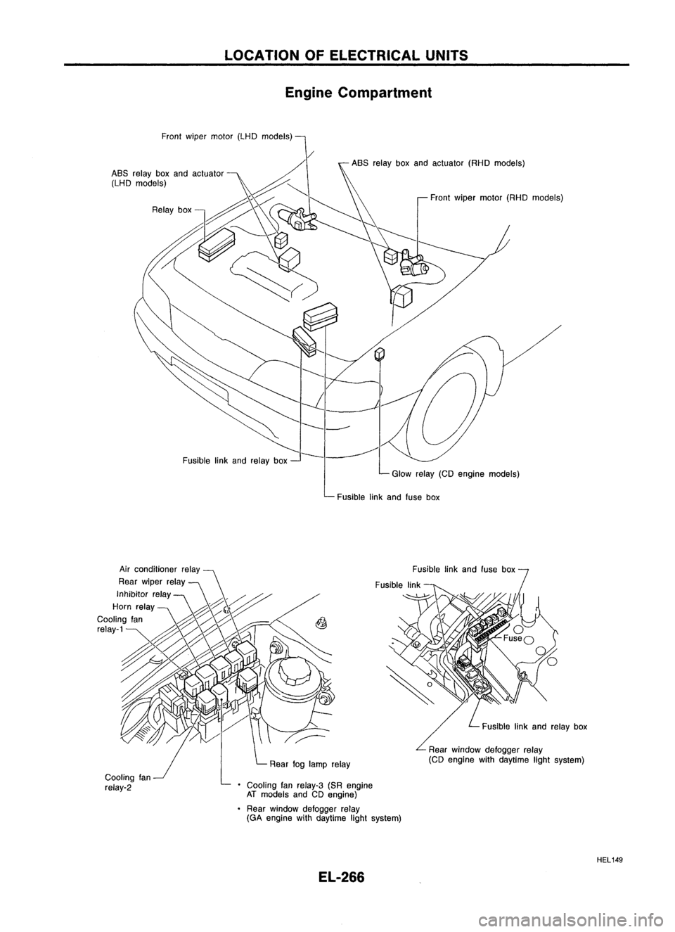
LOCATIONOFELECTRICAL UNITS
Engine Compartment
Front wiper motor (LHDmodels)
Fusible linkand relay box ASS
relay boxand actuator (RHOmodels)
Front wiper motor (RHOmodels)
Glow relay(CDengine models)
Fusible linkand fuse box
Cooling fan
relay-2 Rear
foglamp relay
• Cooling fanrelay-3 (SRengine
AT models andCDengine)
Rear window defogger relay
(GA engine withdaytime lightsystem)
EL-266 Fusible
linkand fuse box
Fusible linkand relay box
Rear window defogger relay
(CD engine withdaytime lightsystem)
HEL149
Page 639 of 1701

LOCATIONOFELECTRICAL UNITS
Passenger Compartment
LHD MODELS
Rearwindow defogger timer
(With daytime lightsystem)
Warning buzzerunit
Combination flasherunit
Junction boxNO.2 (Joint connectors)
Stop lamp switch
Mirror defogger relay
(With daytime lightsystem)
Sun roofrelay (Without powerwindow)
Power window relay(With power window)
Front foglamp relay
SMJ (Main harness-
engine roomharness) NATS
IMMU (Gasoline engine)
Door locktimer
ABS control unit
Front wiper amplifier
SMJ (Main harness-
front doorharness)
SMJ (Main harness-
front doorharness)
Rear wiper amplifier
Daytime lightunit
Circuit breaker
Fuel pump relay
(Gasoline engine)
Fuse block
(JIB)
Ignition relay
Blower relay
Accessory relay Air
bag diagnosis sensorunit
(With dualairbag system)
ECM (ECCS control module) (Gasoline engine)
ECM (Engine controlmodule) (Dieselengine)
ECCS relay(Gasoline engine)
EL-267 HEL
150
•
Page 640 of 1701
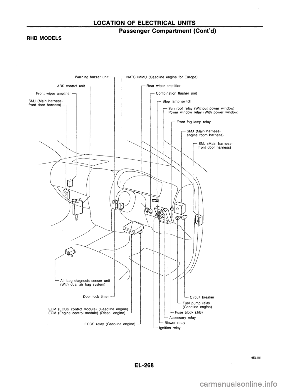
RHOMODELS LOCATION
OFELECTRICAL UNITS
Passenger Compartment (Cont'd)
Warning buzzerunit
ABS control unit
Front wiper amplifier
SMJ (Main harness-
front doorharness) NATS
IMMU (Gasoline engineforEurope)
Rear wiper amplifier
Combination flasherunit
Stop lamp switch
Sun roolrelay (Without powerwindow)
Power window relay(With power window)
Front foglamp relay
SMJ (Main harness-
engine roomharness)
EGM (EGGS controlmodule) (Gasoline engine)
EGM (Engine controlmodule) (Dieselengine)
EGGS relay(Gasoline engine)
EL-268 SMJ
(Main harness-
Iront doorharness)
Circuit breaker
Fuel pump relay
(Gasoline engine)
Fuse block
(JIB)
Accessory relay
Blower relay
Ignition relay
HEL151