NISSAN ALMERA N15 1995 Service Manual
ALMERA N15 1995
NISSAN
NISSAN
https://www.carmanualsonline.info/img/5/57349/w960_57349-0.png
NISSAN ALMERA N15 1995 Service Manual
Trending: LOCATIONS, spare wheel, oil level, cooling, Headlight, width, ESP
Page 611 of 1701
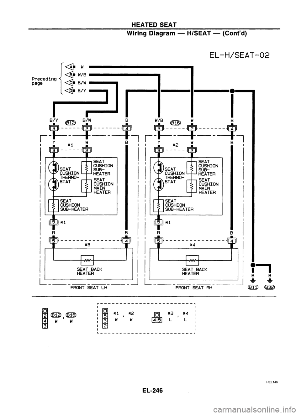
AUDIOANDANTENNA
Wiring Diagram -AUDIO -(Cont'd)
EL-AUDIO-02
•
Models
with
6-speaker
JOINT
CONNECTOR
-1
@)
I'=idJ
B/W
t
RADIO
~
Refer tolast page
(Foldout page).
@:
U4=J1
L
FRSP
LHH
~
B/W
I
t
B/W
rn
I'=idJ
B/W
t
B/W LB/W
m2
PILLAR
t
1
\Q
4
2-
I
DOOR
SPEAKER SPEAKER
LH LH
~:@
@)
FRSP
LH
(+)
~
L
IJ
L
rrtn
~
L
1
I I
I"IIJJIIIITIITi
@)
~BR'BR
FRSP
FRSP
RH
(+)
RHH
~ ~
BR B/R
I
J It
BR B/R
rrtn
rn
JOINT
CONNECTOR
-3
~
4=Jl
~
~
B/R BR
B/R
t
f
t
B/R BRB/R
~ PILLAR J!1
\Q
4
2-
I
DOOR
11211
SPEAKER SPEAKER
RH RH
~:@ ~
[Q]~~(@~
[IIg]
BR'BR 'BR 'BR
CAUTION: Don'tattempt torepair, spliceormodify theflexible
flat circuit (FFC).If the FFC isdamaged, replacewith
a new one.
HEL141
EL-239
Page 612 of 1701
AUDIOANDANTENNA
Wiring Diagram -AUDIO -(Conl'd)
RHO MODELS FOREUROPE
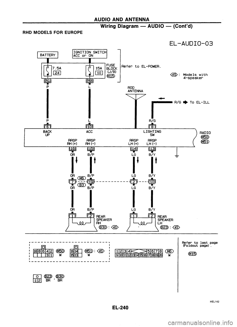
EL-AUDIO-03
RADIO
@
(8[D
Models
with
4-speaker
@:
ROD
ANTENNA
~~5~K
RefertoEL-POWER.
(JIB)
(8Th)
L
rrfcrn
ACC
....
,......... AlG~ToEL-ILL
RIG
m
LIGHTING
SW
RRSP RRSP RRSPRRSP
RH
(+)
RH(-) LH
(+)
LH(-)
~ ~ ~~
OR B/P LGB/Y
I • I
t
I• I
t
OR
<:MID
B/P LGB/Y
I~~
-i:-~.~ -------- -- -
~$~ ---
~$I
OR
@)
B/P LGB/Y
I I II
P
m
BACK
UP
ORB/P
J!oo~~AA
SPEAKER
RH
@:@
~-------------------------~
I
I
(8[D:@
I
W :
I I
~-------------------------j
W
Refer
tolast page
(Foldout page).
[Q]~@)
[!gJ
BR•BR
HEL142
EL-240
Page 613 of 1701
AUDIOANDANTENNA
Wiring Diagram -AUDIO -(Cont'd)
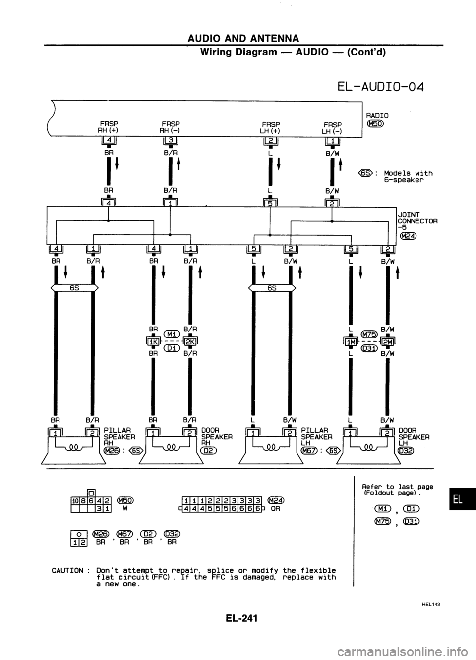
EL-AUDIO-04
FRSP
RH
(+)
~
BR
I
J
BR
m FRSP
RHH
Ibi=ll
B/R
I
t
B/R
m FRSP
LH
(+)
~
L
I
J
L
IFtil
FRSP
LH (-)
IbjdJ
B/W
I
t
B/W
ri1=TI
RADIO
@)
@:
Models with
6-speaker
•
JOINT
CONNECTOR
-5
@)
~
B/W
t
~
L
L ~B/W
I$~---~.I
L ~B/W
~
B/W
t
Refertolast page
(Fo ldout page).
~
L
L B/W LB/W
~~ ~PILLAA
[tooljrom
111
II
11-2
IISPEAKER II1II II2 IISPEAKER
LH LH
~:@
@
l6i=!J
B/R
t
~~
~OR
l!4=U
BR
J
l6i=!J
B/R
t
1
1
I
I
I
I
[Q]~~@)~
[I[g]
BR•BR •BR •BR
CAUTION: Don'tattempt torepair. spliceormodify theflexible
flat circuit (FFC).If the FFC isdamaged. replacewith
a new one.
HEL143
EL-241
Page 614 of 1701
AUDIOANDANTENNA
Wiring Diagram -AUDIO -(Cont'd)
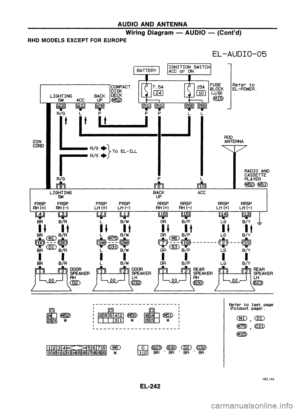
RHD MODELS EXCEPTFOREUROPE
EL-AUDIO-05
RADIOAND
CASSETTE
PLAYER
~ (fID)
RRSP
LH (-)
~
B/Y
-
ROD
ANTENNA
RRSP
LH (+)
~
LG
FUSE
Referto
BLOCK EL-POWER.
(JIB)
~
L
IffoD
ACC
RRSP
RH (-)
~
B/P
COMPACT
DISK
BACK DECK
UP ~
1
2•4
1 ~~
P P
I_t __ I
LIGHTING
SW
1
2
:1
RIG
t
FRSP
RH
(+)
I!4=Jl
BR
DIN
CORD
~~
~W
r---------------------~
I
I
~I
W :
I
Refer
tolast page
(Foldout page).
[Q] ~
@
C02)
@
[IIg]
BR.BR .BR .BR
HEL144
EL-242
Page 615 of 1701
AUDIOANDANTENNA
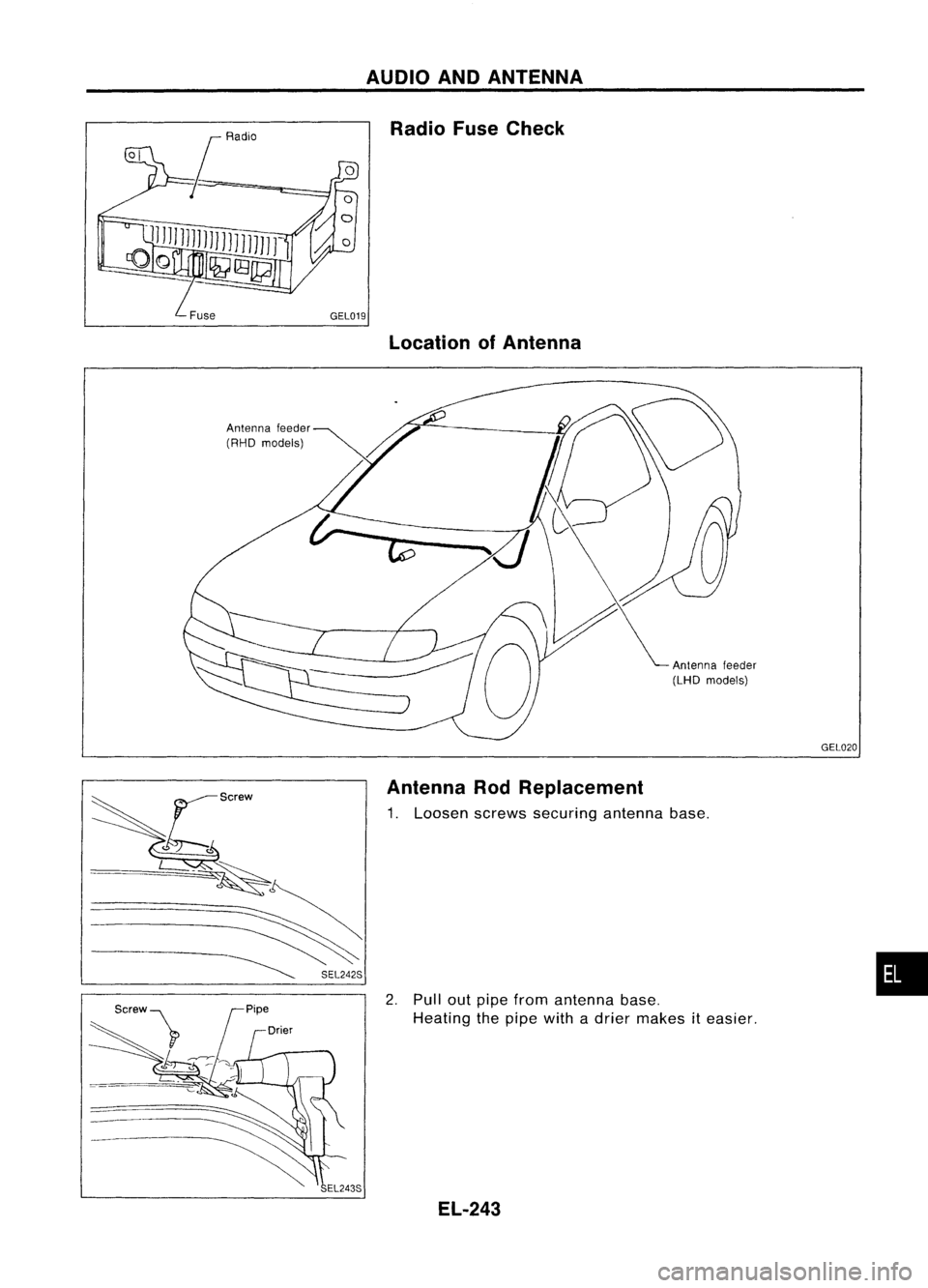
Antenna feeder
(RHO models) Radio
FuseCheck
Location ofAntenna
Antennafeeder
(LHO models)
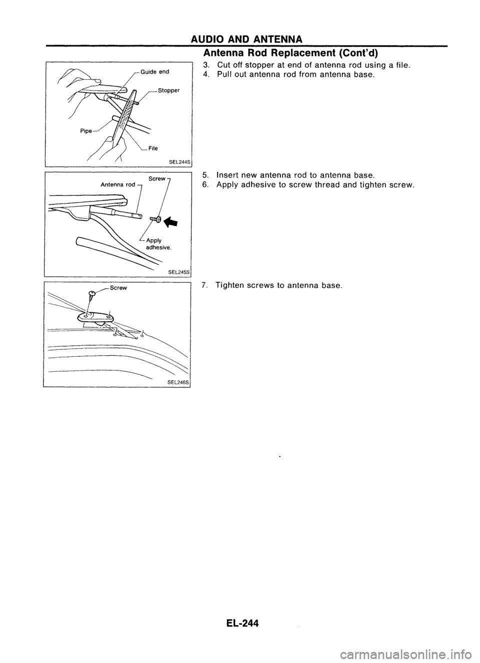
Antenna RodReplacement
1. Loosen screwssecuring antennabase.
2. Pullout pipefrom antenna base.
Heating thepipe withadrier makes
it
easier.
EL-243 GEL020
•
Page 616 of 1701
AUDIOANDANTENNA
Antenna RodReplacement (Cont'd)
3. Cut offstopper atend ofantenna rodusing afile.
4. Pullout antenna rodfrom antenna base.
5. Insert newantenna rodtoantenna base.
6. Apply adhesive toscrew thread andtighten screw.
7. Tighten screwstoantenna base.
EL-244
Page 617 of 1701
HEATEDSEAT
*
For location ofheating unit,refer to"SEAT" inBT section.
Wiring Diagram -HIS EAT -
EL-H/SEAT-01
IGNITION SWITCH
ON orSTART
FUSEReferto
BLOCK EL-POWER.
(JIB)
(]V
I
R R
w=n w=n
Nextpage
~
lb4=Jl ~~~
B/W B W/BWB
1----1-1::
1
-w-G>
-W/B~
'I-B/W~
II-B/Y~
HI
-
La Rf- -
La -Rf-
LOHEATED
HI
-l5
Rf- -la-Rf-
LOHEATED
SEAT SEAT
•
SWITCH
•
SWITCH
OFF OFF LH
OFFOFF RH
(B13)
~
~
B/Y
f.
B B
~ ~
<[il) ~
Refertolast page •
(Foldout page).
HEL 145
EL-245
Page 618 of 1701
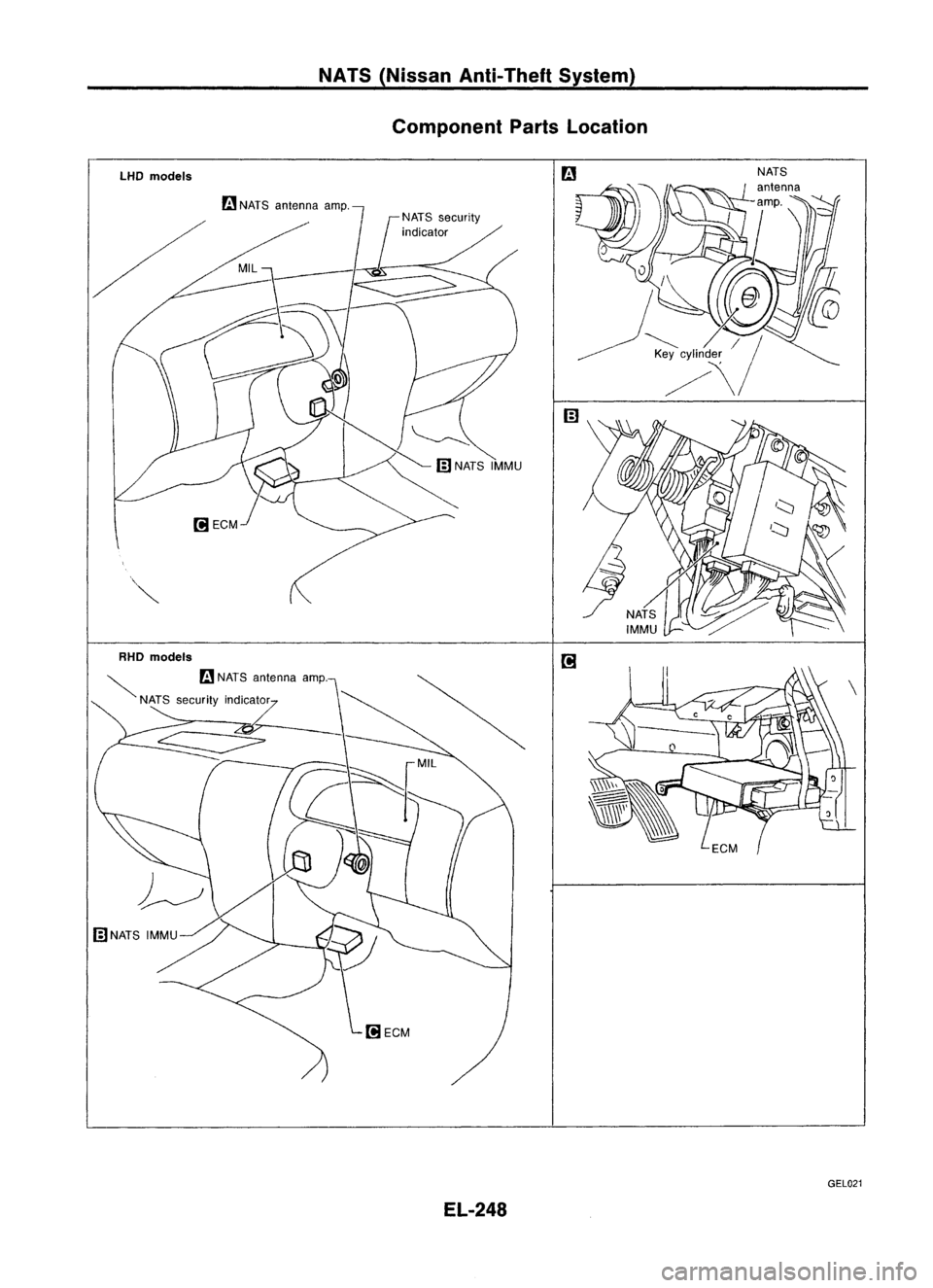
HEATEDSEAT
Wiring Diagram -H/SEAT -(Cont'd)
EL-H/SEAT-02
,.
B B
~ ~
~ @)
~W
<@-
W/B------- ....
~B/W---.
B/Y
-"'1
I
I
B/Y ~ B/W BW/B~ W B
$-----$-------~ $-----$-------~
i-t----t------t, i-t----t------t,
I
Y *1 W B
I
Y*2 W B
I
I
m-----ffl
I
m-----ffl
I
SEAT SEAT
I
CUSHION
I
CUSHION
II
I
SUB-
I
SUB-
HEATER HEATER
SEAT SEAT
I
CUSHION
I
CUSHION
II
I
MAIN
I
MAIN
HEATER HEATER
I I I
I I I
I I I
I I I
I I I
I I....,I
I I I
I
SEATBACK
I
SEATBACK
I
I
HEATER
I
HEATER
I
L: ~L: ~
FRONT SEATLH FRONTSEATRH
Preceding
page
r------------------------~
;2
~,@
4 W W
3
I
I ~
*1 *2
I
5 ,
: 3 W W
I
2
I I
I
J'QL
*3,*4
I
~ LL:
I
I
~------------------------~
HEL146
EL-246
Page 619 of 1701
NATS(Nissan Anti-Theft System)
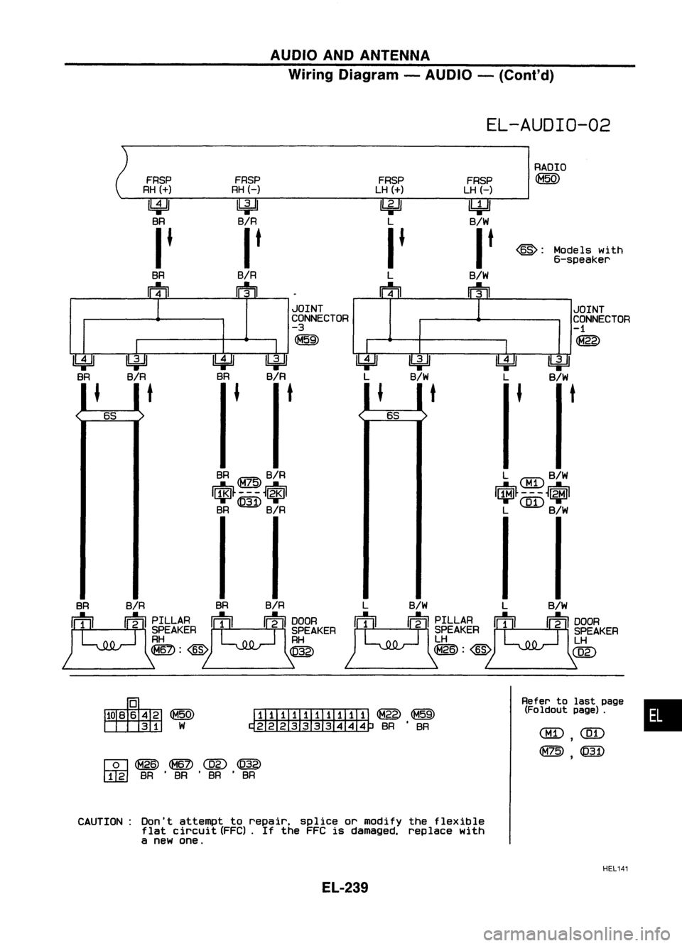
System Description
NATS V2.0forNissan modelN15hasthefollowing immobiliser functions:
• Since onlyNATS ignition keys,whose IDnos. have been registered intotheECM andIMMU ofNATS,
allow theengine torun, operation ofastolen vehicle withoutaNATS registered keyisprevented by
NATS.
That isto say, NATS V2.0willimmobilize theengine ifsomeone triestostart itwithout theregis-
tered keyofNATS V2.0.
• Both ofthe originally suppliedignitionkeyIDshave been NATS registered.
If requested bythe vehicle owner,amaximum offour keyIDscan beregistered intotheNATS com-
ponents.
• The NATS security indicator (NATSsecurity ind.)blinks whentheignition switchisin "OFF" or
"ACC" position. Therefore, NATSwarns outsiders thatthevehicle isequipped withtheanti-theft
system.
• When NATSdetects trouble, themalfunction indicatorlamp(MIL) blinks.
• NATS trouble diagnoses, systeminitialisation andadditional registration ofother NATS ignition key
IDs must becarried outusing CONSULT hardwareandCONSULT NATSsoftware.
When NATS initialisation hasbeen completed, theIDofthe inserted ignitionkeyisautomatically
NATS registered. Then,ifnecessary, additionalregistration ofother NATS ignition keyIDscan be
carried out.
Regarding theprocedures ofNATS initialisation andNATS ignition keyIDregistration, refertoCON-
SUL Toperation manual,NATSV2.0.
• When diagnosing NATSV2.0using CONSULT, adapterandadapter harness forNATS V1.0arenot
necessary, althoughadirect DDLcable connection betweenCONSULT andDOL connector is
required.
• When servicing amalfunction ofthe NATS V2.0(indicated byflashing ofMalfunction IndicatorLamp)
or registering anotherNATSignition keyIDno., itmay benecessary tore-register originalkeyiden-
tification. Therefore, besure toreceive allkeys from vehicle owner.
System Composition
The immobiliser functionofthe NATS forNissan modelN15consists ofthe following:
• NATS ignition key
• NATS antenna amp.located inthe ignition keycylinder
• NATS immobiliser controlunit(NATS IMMU)
• Engine control module (ECM)
• NATS security indicator locatedunderthecenter cluster (NATSsecurity ind.)
• Malfunction indicatorlamp(MIL)
NATS ignition key
(
((
(
El-247
SEL304U
•
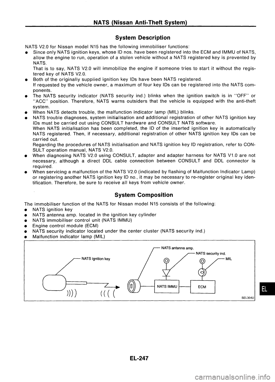
Page 620 of 1701
NATS(Nissan Anti-Theft System)
Component PartsLocation
LHO models
rn
NATS antenna amp.
RHO models
~ rn
NATS antenna amp.
NATS security indicator
EL-248 GEL021
Trending: belt, door lock, Manual trans, turn signal bulb, check oil, sensor, engine oil capacity
![NISSAN ALMERA N15 1995 Service Manual HEATEDSEAT
*
For location ofheating unit,refer to"SEAT" inBT section.
Wiring Diagram -HIS EAT -
EL-H/SEAT-01
IGNITION SWITCH
ON orSTART
FUSEReferto
BLOCK EL-POWER.
(JIB)
(]V
I
R R
w=n NISSAN ALMERA N15 1995 Service Manual HEATEDSEAT
*
For location ofheating unit,refer to"SEAT" inBT section.
Wiring Diagram -HIS EAT -
EL-H/SEAT-01
IGNITION SWITCH
ON orSTART
FUSEReferto
BLOCK EL-POWER.
(JIB)
(]V
I
R R
w=n](/img/5/57349/w960_57349-616.png)
