NISSAN ALMERA N16 2001 Electronic Repair Manual
Manufacturer: NISSAN, Model Year: 2001, Model line: ALMERA N16, Model: NISSAN ALMERA N16 2001Pages: 2493, PDF Size: 66.97 MB
Page 991 of 2493

4 CHECK INTERMITTENT INCIDENT
Refer to ªTROUBLE DIAGNOSIS FOR INTERMITTENT INCIDENTº, EC-559.
©INSPECTION END
START SIGNALYD
Diagnostic Procedure (Cont'd)
EC-695
Page 992 of 2493
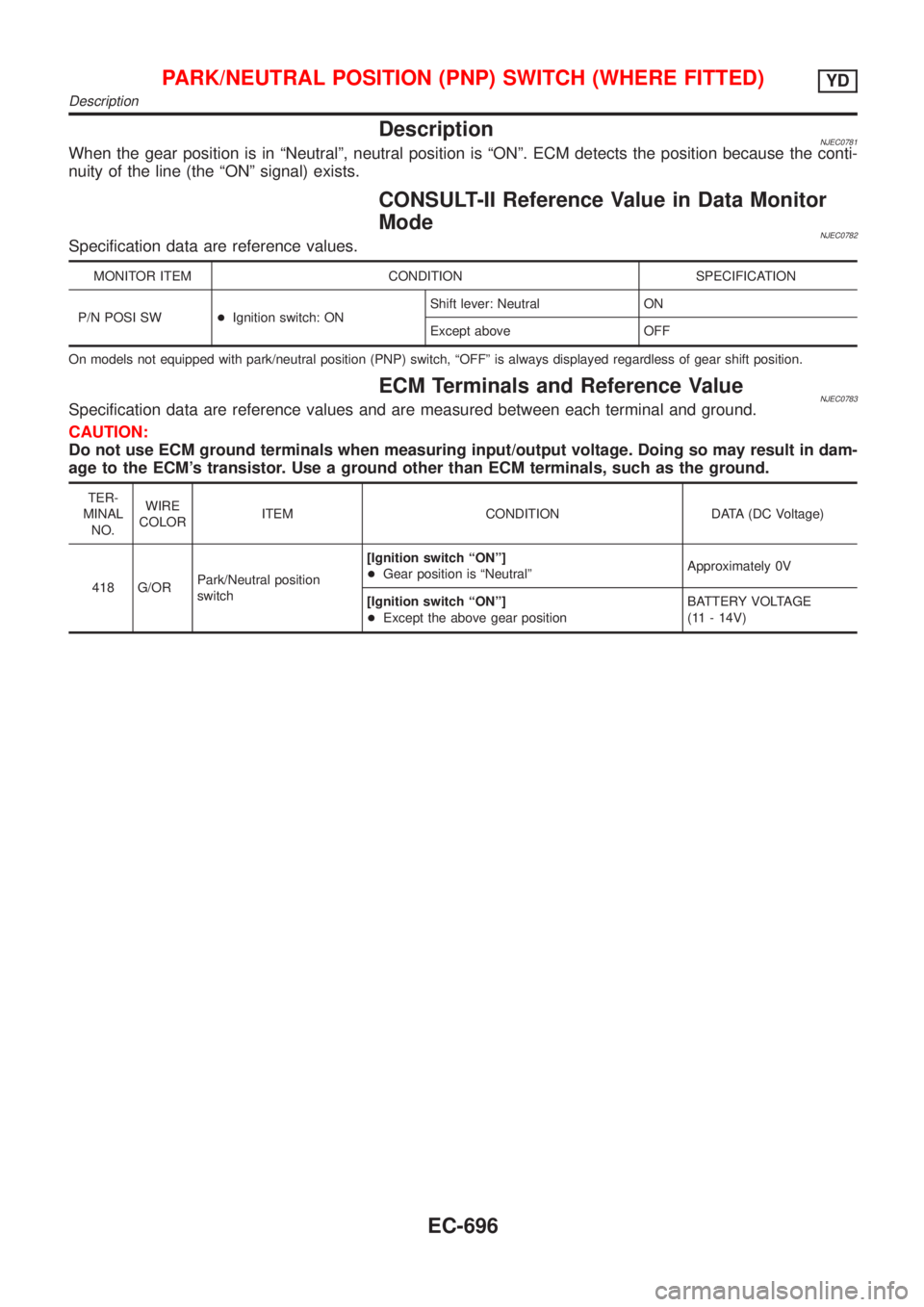
DescriptionNJEC0781When the gear position is in ªNeutralº, neutral position is ªONº. ECM detects the position because the conti-
nuity of the line (the ªONº signal) exists.
CONSULT-II Reference Value in Data Monitor
Mode
NJEC0782Specification data are reference values.
MONITOR ITEM CONDITION SPECIFICATION
P/N POSI SW+Ignition switch: ONShift lever: Neutral ON
Except above OFF
On models not equipped with park/neutral position (PNP) switch, ªOFFº is always displayed regardless of gear shift position.
ECM Terminals and Reference ValueNJEC0783Specification data are reference values and are measured between each terminal and ground.
CAUTION:
Do not use ECM ground terminals when measuring input/output voltage. Doing so may result in dam-
age to the ECM's transistor. Use a ground other than ECM terminals, such as the ground.
TER-
MINAL
NO.WIRE
COLORITEM CONDITION DATA (DC Voltage)
418 G/ORPark/Neutral position
switch[Ignition switch ªONº]
+Gear position is ªNeutralºApproximately 0V
[Ignition switch ªONº]
+Except the above gear positionBATTERY VOLTAGE
(11 - 14V)
PARK/NEUTRAL POSITION (PNP) SWITCH (WHERE FITTED)YD
Description
EC-696
Page 993 of 2493
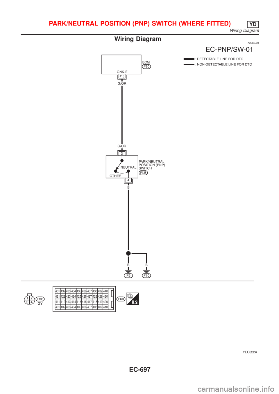
Wiring DiagramNJEC0784
YEC022A
PARK/NEUTRAL POSITION (PNP) SWITCH (WHERE FITTED)YD
Wiring Diagram
EC-697
Page 994 of 2493
Diagnostic ProcedureNJEC0785
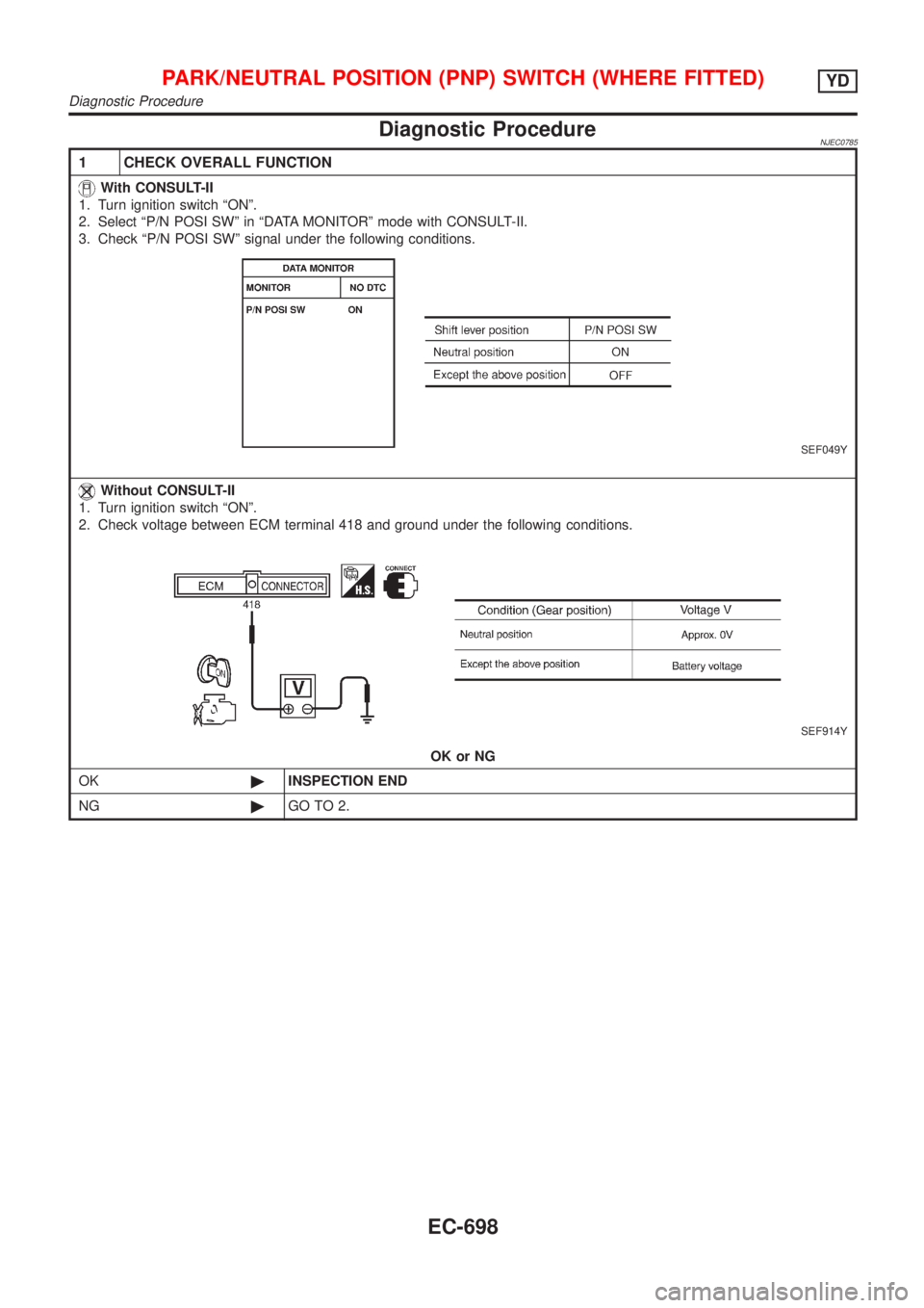
1 CHECK OVERALL FUNCTION
With CONSULT-II
1. Turn ignition switch ªONº.
2. Select ªP/N POSI SWº in ªDATA MONITORº mode with CONSULT-II.
3. Check ªP/N POSI SWº signal under the following conditions.
SEF049Y
Without CONSULT-II
1. Turn ignition switch ªONº.
2. Check voltage between ECM terminal 418 and ground under the following conditions.
SEF914Y
OK or NG
OK©INSPECTION END
NG©GO TO 2.
PARK/NEUTRAL POSITION (PNP) SWITCH (WHERE FITTED)YD
Diagnostic Procedure
EC-698
Page 995 of 2493
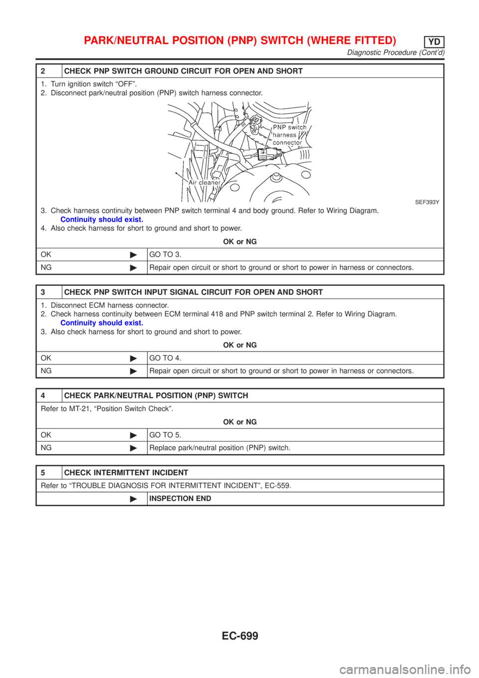
2 CHECK PNP SWITCH GROUND CIRCUIT FOR OPEN AND SHORT
1. Turn ignition switch ªOFFº.
2. Disconnect park/neutral position (PNP) switch harness connector.
SEF393Y
3. Check harness continuity between PNP switch terminal 4 and body ground. Refer to Wiring Diagram.
Continuity should exist.
4. Also check harness for short to ground and short to power.
OK or NG
OK©GO TO 3.
NG©Repair open circuit or short to ground or short to power in harness or connectors.
3 CHECK PNP SWITCH INPUT SIGNAL CIRCUIT FOR OPEN AND SHORT
1. Disconnect ECM harness connector.
2. Check harness continuity between ECM terminal 418 and PNP switch terminal 2. Refer to Wiring Diagram.
Continuity should exist.
3. Also check harness for short to ground and short to power.
OK or NG
OK©GO TO 4.
NG©Repair open circuit or short to ground or short to power in harness or connectors.
4 CHECK PARK/NEUTRAL POSITION (PNP) SWITCH
Refer to MT-21, ªPosition Switch Checkº.
OK or NG
OK©GO TO 5.
NG©Replace park/neutral position (PNP) switch.
5 CHECK INTERMITTENT INCIDENT
Refer to ªTROUBLE DIAGNOSIS FOR INTERMITTENT INCIDENTº, EC-559.
©INSPECTION END
PARK/NEUTRAL POSITION (PNP) SWITCH (WHERE FITTED)YD
Diagnostic Procedure (Cont'd)
EC-699
Page 996 of 2493
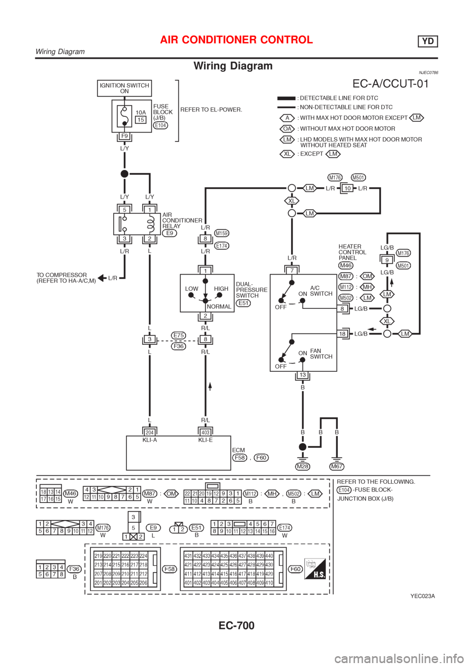
Wiring DiagramNJEC0786
YEC023A
AIR CONDITIONER CONTROLYD
Wiring Diagram
EC-700
Page 997 of 2493
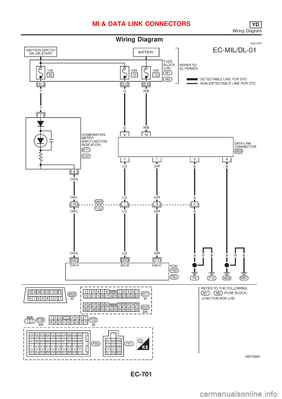
Wiring DiagramNJEC0787
NEF399A
MI & DATA LINK CONNECTORSYD
Wiring Diagram
EC-701
Page 998 of 2493
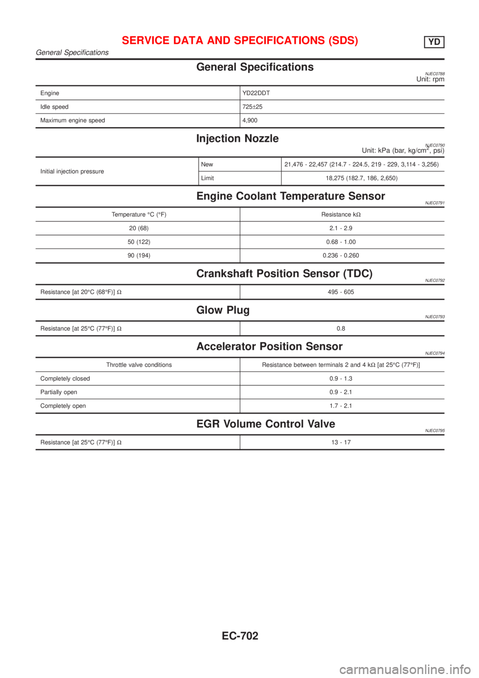
General SpecificationsNJEC0788Unit: rpm
Engine YD22DDT
Idle speed 725±25
Maximum engine speed 4,900
Injection NozzleNJEC0790Unit: kPa (bar, kg/cm2, psi)
Initial injection pressureNew 21,476 - 22,457 (214.7 - 224.5, 219 - 229, 3,114 - 3,256)
Limit 18,275 (182.7, 186, 2,650)
Engine Coolant Temperature SensorNJEC0791
Temperature ÉC (ÉF) Resistance kW
20 (68) 2.1 - 2.9
50 (122) 0.68 - 1.00
90 (194) 0.236 - 0.260
Crankshaft Position Sensor (TDC)NJEC0792
Resistance [at 20ÉC (68ÉF)]W495 - 605
Glow PlugNJEC0793
Resistance [at 25ÉC (77ÉF)]W0.8
Accelerator Position SensorNJEC0794
Throttle valve conditions Resistance between terminals 2 and 4 kW[at 25ÉC (77ÉF)]
Completely closed0.9 - 1.3
Partially open0.9 - 2.1
Completely open1.7 - 2.1
EGR Volume Control ValveNJEC0795
Resistance [at 25ÉC (77ÉF)]W13-17
SERVICE DATA AND SPECIFICATIONS (SDS)YD
General Specifications
EC-702
Page 999 of 2493
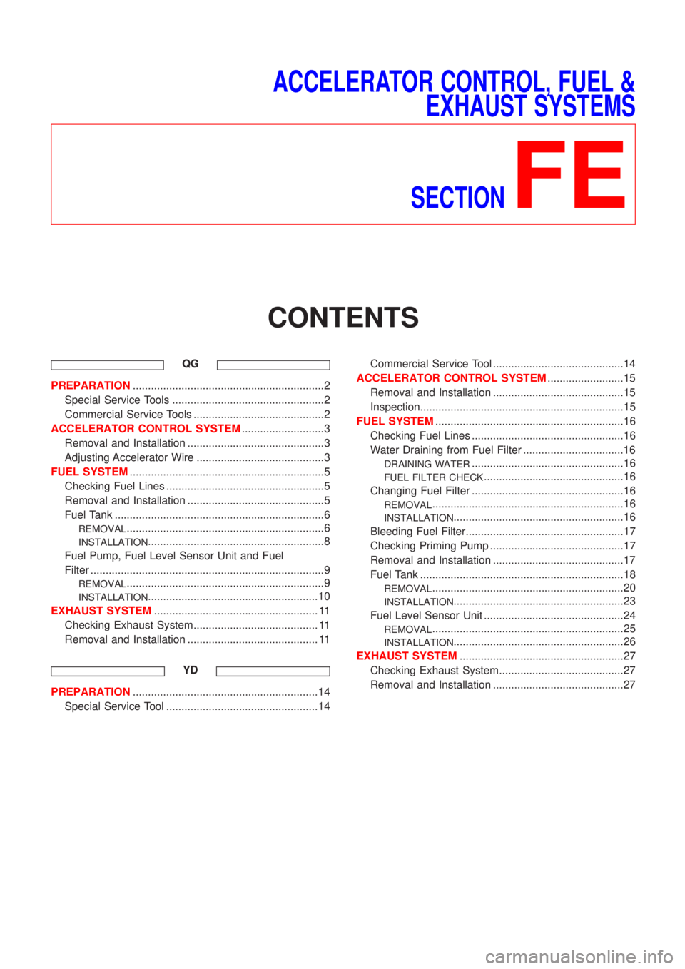
ACCELERATOR CONTROL, FUEL &
EXHAUST SYSTEMS
SECTION
FE
CONTENTS
QG
PREPARATION...............................................................2
Special Service Tools ..................................................2
Commercial Service Tools ...........................................2
ACCELERATOR CONTROL SYSTEM...........................3
Removal and Installation .............................................3
Adjusting Accelerator Wire ..........................................3
FUEL SYSTEM................................................................5
Checking Fuel Lines ....................................................5
Removal and Installation .............................................5
Fuel Tank .....................................................................6
REMOVAL.................................................................6
INSTALLATION..........................................................8
Fuel Pump, Fuel Level Sensor Unit and Fuel
Filter .............................................................................9
REMOVAL.................................................................9
INSTALLATION........................................................10
EXHAUST SYSTEM...................................................... 11
Checking Exhaust System......................................... 11
Removal and Installation ........................................... 11
YD
PREPARATION.............................................................14
Special Service Tool ..................................................14Commercial Service Tool ...........................................14
ACCELERATOR CONTROL SYSTEM.........................15
Removal and Installation ...........................................15
Inspection...................................................................15
FUEL SYSTEM..............................................................16
Checking Fuel Lines ..................................................16
Water Draining from Fuel Filter .................................16
DRAINING WATER..................................................16
FUEL FILTER CHECK..............................................16
Changing Fuel Filter ..................................................16
REMOVAL...............................................................16
INSTALLATION........................................................16
Bleeding Fuel Filter....................................................17
Checking Priming Pump ............................................17
Removal and Installation ...........................................17
Fuel Tank ...................................................................18
REMOVAL...............................................................20
INSTALLATION........................................................23
Fuel Level Sensor Unit ..............................................24
REMOVAL...............................................................25
INSTALLATION........................................................26
EXHAUST SYSTEM......................................................27
Checking Exhaust System.........................................27
Removal and Installation ...........................................27
Page 1000 of 2493
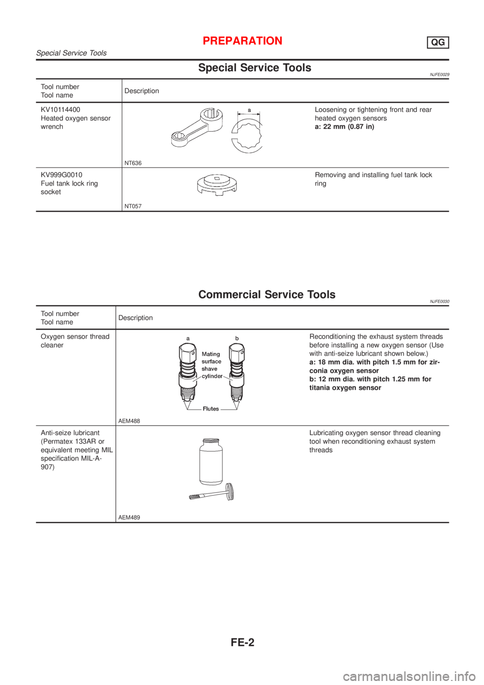
Special Service ToolsNJFE0029
Tool number
Tool nameDescription
KV10114400
Heated oxygen sensor
wrench
NT636
Loosening or tightening front and rear
heated oxygen sensors
a: 22 mm (0.87 in)
KV999G0010
Fuel tank lock ring
socket
NT057
Removing and installing fuel tank lock
ring
Commercial Service ToolsNJFE0030
Tool number
Tool nameDescription
Oxygen sensor thread
cleaner
AEM488
Reconditioning the exhaust system threads
before installing a new oxygen sensor (Use
with anti-seize lubricant shown below.)
a: 18 mm dia. with pitch 1.5 mm for zir-
conia oxygen sensor
b: 12 mm dia. with pitch 1.25 mm for
titania oxygen sensor
Anti-seize lubricant
(Permatex 133AR or
equivalent meeting MIL
specification MIL-A-
907)
AEM489
Lubricating oxygen sensor thread cleaning
tool when reconditioning exhaust system
threads
PREPARATIONQG
Special Service Tools
FE-2