NISSAN ALMERA N16 2001 Electronic Repair Manual
ALMERA N16 2001
NISSAN
NISSAN
https://www.carmanualsonline.info/img/5/57351/w960_57351-0.png
NISSAN ALMERA N16 2001 Electronic Repair Manual
Trending: light adjustment, service interval, iac, replace audio cable, four wheel drive, ad blue, child restraint
Page 2301 of 2493
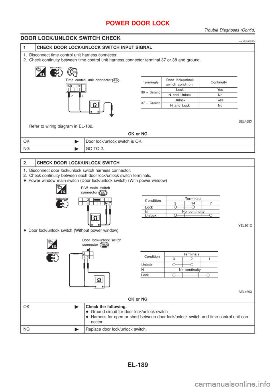
DOOR LOCK/UNLOCK SWITCH CHECK=NJEL0505S04
1 CHECK DOOR LOCK/UNLOCK SWITCH INPUT SIGNAL
1. Disconnect time control unit harness connector.
2. Check continuity between time control unit harness connector terminal 37 or 38 and ground.
SEL468X
Refer to wiring diagram in EL-182.
OK or NG
OK©Door lock/unlock switch is OK.
NG©GO TO 2.
2 CHECK DOOR LOCK/UNLOCK SWITCH
1. Disconnect door lock/unlock switch harness connector.
2. Check continuity between each door lock/unlock switch terminals.
+Power window main switch (Door lock/unlock switch) (With power window)
YEL801C
+Door lock/unlock switch (Without power window)
SEL469X
OK or NG
OK©Check the following.
+Ground circuit for door lock/unlock switch
+Harness for open or short between door lock/unlock switch and time control unit con-
nector
NG©Replace door lock/unlock switch.
POWER DOOR LOCK
Trouble Diagnoses (Cont'd)
EL-189
Page 2302 of 2493
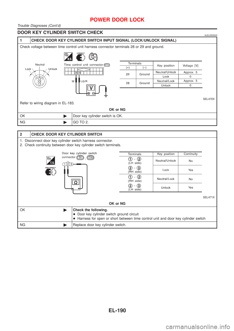
DOOR KEY CYLINDER SWITCH CHECKNJEL0505S05
1 CHECK DOOR KEY CYLINDER SWITCH INPUT SIGNAL (LOCK/UNLOCK SIGNAL)
Check voltage between time control unit harness connector terminals 28 or 29 and ground.
SEL470X
Refer to wiring diagram in EL-183.
OK or NG
OK©Door key cylinder switch is OK.
NG©GO TO 2.
2 CHECK DOOR KEY CYLINDER SWITCH
1. Disconnect door key cylinder switch harness connector.
2. Check continuity between door key cylinder switch terminals.
SEL471X
OK or NG
OK©Check the following.
+Door key cylinder switch ground circuit
+Harness for open or short between time control unit and door key cylinder switch
NG©Replace door key cylinder switch.
POWER DOOR LOCK
Trouble Diagnoses (Cont'd)
EL-190
Page 2303 of 2493
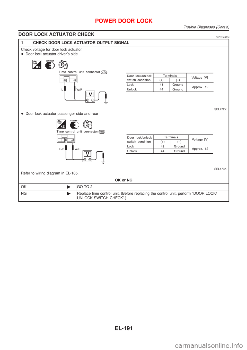
DOOR LOCK ACTUATOR CHECKNJEL0505S06
1 CHECK DOOR LOCK ACTUATOR OUTPUT SIGNAL
Check voltage for door lock actuator.
+Door lock actuator driver's side
SEL472X
+Door lock actuator passenger side and rear
SEL473X
Refer to wiring diagram in EL-185.
OK or NG
OK©GO TO 2.
NG©Replace time control unit. (Before replacing the control unit, perform ªDOOR LOCK/
UNLOCK SWITCH CHECKº.)
POWER DOOR LOCK
Trouble Diagnoses (Cont'd)
EL-191
Page 2304 of 2493
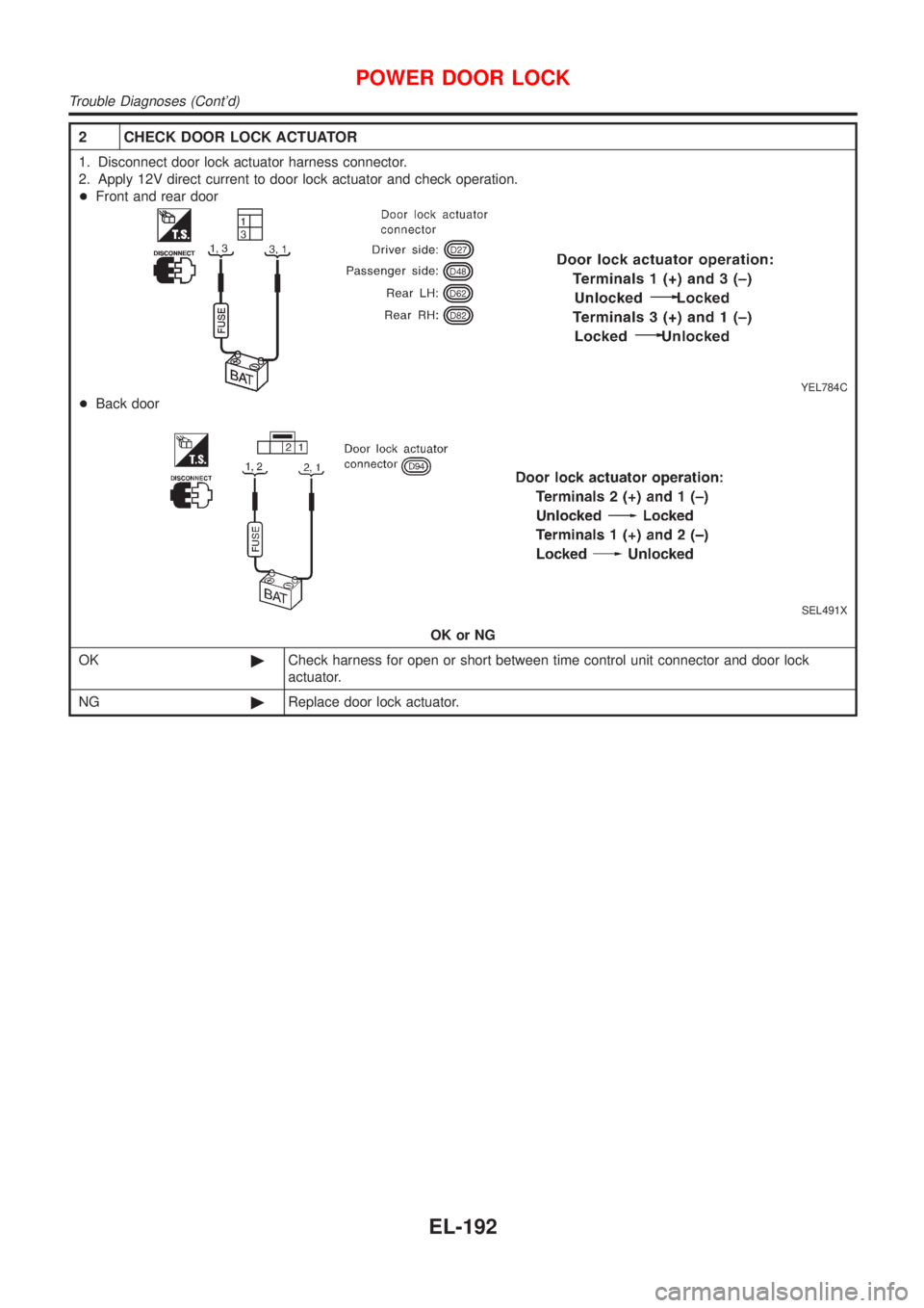
2 CHECK DOOR LOCK ACTUATOR
1. Disconnect door lock actuator harness connector.
2. Apply 12V direct current to door lock actuator and check operation.
+Front and rear door
YEL784C
+Back door
SEL491X
OK or NG
OK©Check harness for open or short between time control unit connector and door lock
actuator.
NG©Replace door lock actuator.
POWER DOOR LOCK
Trouble Diagnoses (Cont'd)
EL-192
Page 2305 of 2493
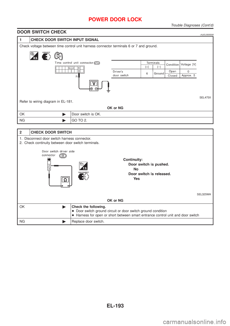
DOOR SWITCH CHECK=NJEL0505S08
1 CHECK DOOR SWITCH INPUT SIGNAL
Check voltage between time control unit harness connector terminals 6 or 7 and ground.
SEL475X
Refer to wiring diagram in EL-181.
OK or NG
OK©Door switch is OK.
NG©GO TO 2.
2 CHECK DOOR SWITCH
1. Disconnect door switch harness connector.
2. Check continuity between door switch terminals.
SEL325WA
OK or NG
OK©Check the following.
+Door switch ground circuit or door switch ground condition
+Harness for open or short between smart entrance control unit and door switch
NG©Replace door switch.
POWER DOOR LOCK
Trouble Diagnoses (Cont'd)
EL-193
Page 2306 of 2493
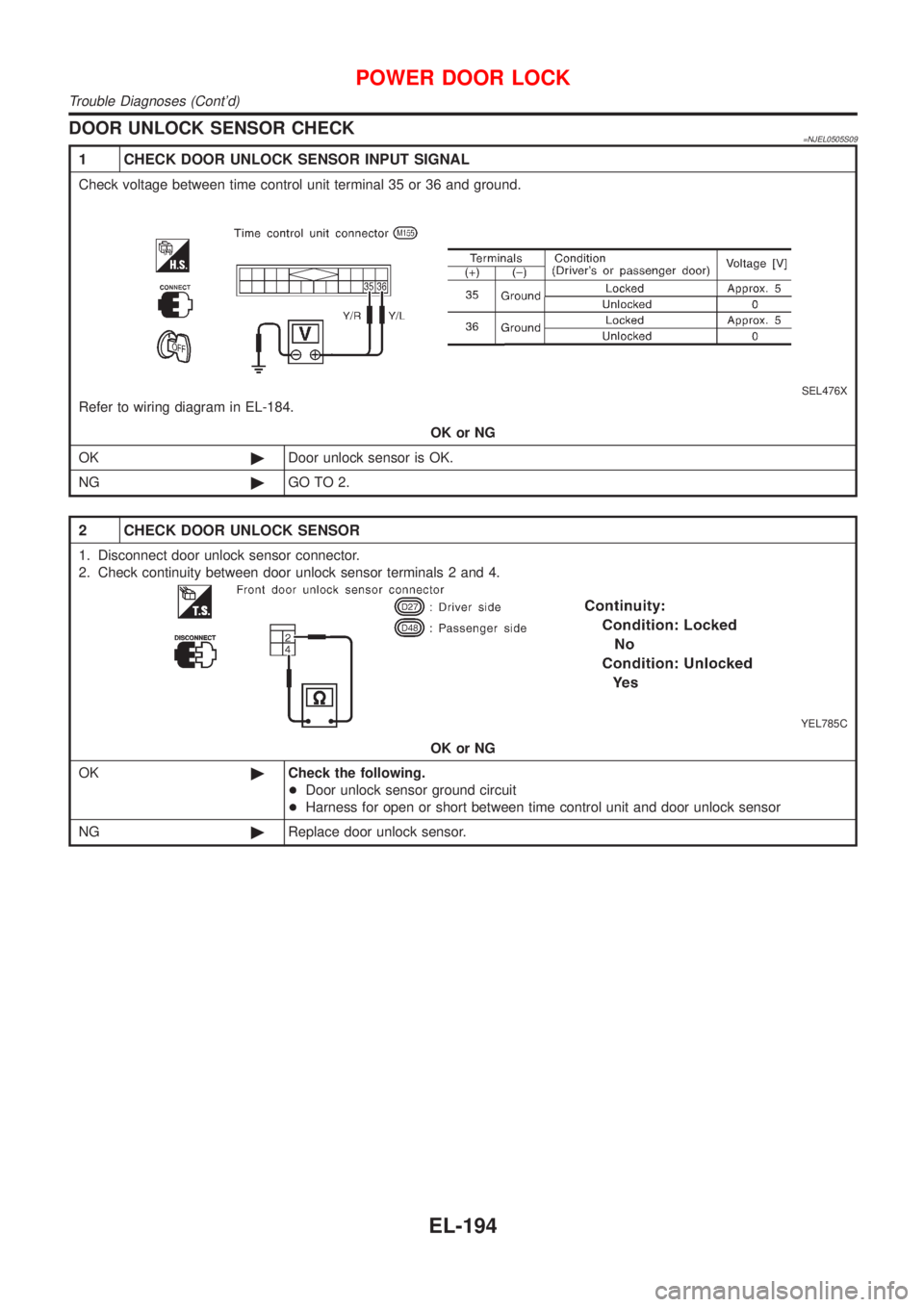
DOOR UNLOCK SENSOR CHECK=NJEL0505S09
1 CHECK DOOR UNLOCK SENSOR INPUT SIGNAL
Check voltage between time control unit terminal 35 or 36 and ground.
SEL476X
Refer to wiring diagram in EL-184.
OK or NG
OK©Door unlock sensor is OK.
NG©GO TO 2.
2 CHECK DOOR UNLOCK SENSOR
1. Disconnect door unlock sensor connector.
2. Check continuity between door unlock sensor terminals 2 and 4.
YEL785C
OK or NG
OK©Check the following.
+Door unlock sensor ground circuit
+Harness for open or short between time control unit and door unlock sensor
NG©Replace door unlock sensor.
POWER DOOR LOCK
Trouble Diagnoses (Cont'd)
EL-194
Page 2307 of 2493
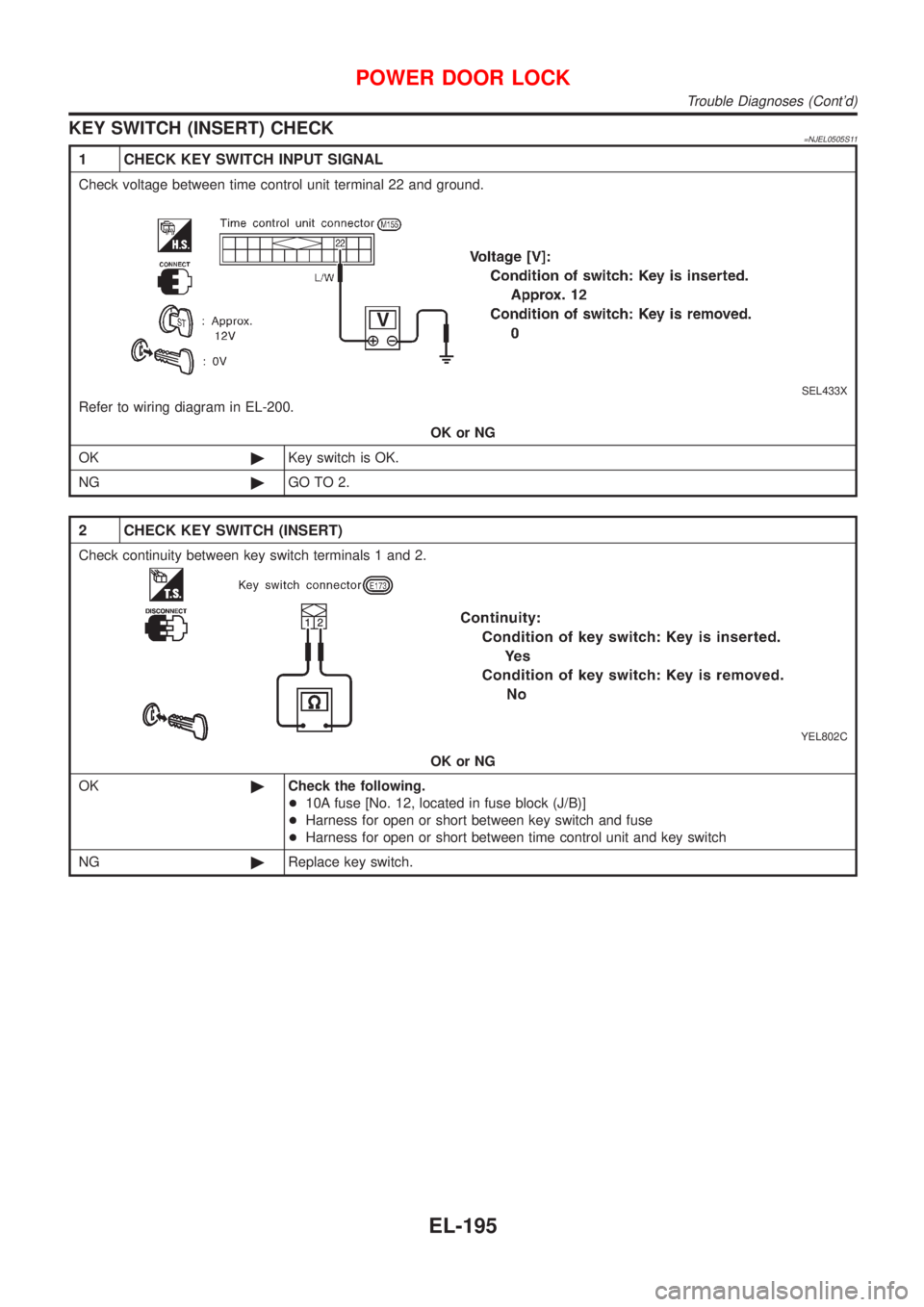
KEY SWITCH (INSERT) CHECK=NJEL0505S11
1 CHECK KEY SWITCH INPUT SIGNAL
Check voltage between time control unit terminal 22 and ground.
SEL433X
Refer to wiring diagram in EL-200.
OK or NG
OK©Key switch is OK.
NG©GO TO 2.
2 CHECK KEY SWITCH (INSERT)
Check continuity between key switch terminals 1 and 2.
YEL802C
OK or NG
OK©Check the following.
+10A fuse [No. 12, located in fuse block (J/B)]
+Harness for open or short between key switch and fuse
+Harness for open or short between time control unit and key switch
NG©Replace key switch.
POWER DOOR LOCK
Trouble Diagnoses (Cont'd)
EL-195
Page 2308 of 2493
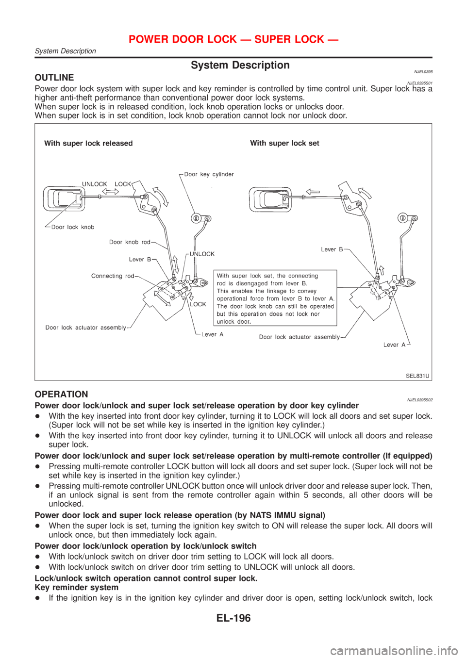
System DescriptionNJEL0395OUTLINENJEL0395S01Power door lock system with super lock and key reminder is controlled by time control unit. Super lock has a
higher anti-theft performance than conventional power door lock systems.
When super lock is in released condition, lock knob operation locks or unlocks door.
When super lock is in set condition, lock knob operation cannot lock nor unlock door.
SEL831U
OPERATIONNJEL0395S02Power door lock/unlock and super lock set/release operation by door key cylinder
+With the key inserted into front door key cylinder, turning it to LOCK will lock all doors and set super lock.
(Super lock will not be set while key is inserted in the ignition key cylinder.)
+With the key inserted into front door key cylinder, turning it to UNLOCK will unlock all doors and release
super lock.
Power door lock/unlock and super lock set/release operation by multi-remote controller (If equipped)
+Pressing multi-remote controller LOCK button will lock all doors and set super lock. (Super lock will not be
set while key is inserted in the ignition key cylinder.)
+Pressing multi-remote controller UNLOCK button once will unlock driver door and release super lock. Then,
if an unlock signal is sent from the remote controller again within 5 seconds, all other doors will be
unlocked.
Power door lock and super lock release operation (by NATS IMMU signal)
+When the super lock is set, turning the ignition key switch to ON will release the super lock. All doors will
unlock once, but then immediately lock again.
Power door lock/unlock operation by lock/unlock switch
+With lock/unlock switch on driver door trim setting to LOCK will lock all doors.
+With lock/unlock switch on driver door trim setting to UNLOCK will unlock all doors.
Lock/unlock switch operation cannot control super lock.
Key reminder system
+If the ignition key is in the ignition key cylinder and driver door is open, setting lock/unlock switch, lock
POWER DOOR LOCK Ð SUPER LOCK Ð
System Description
EL-196
Page 2309 of 2493
knob, key or multi-remote controller to ªLOCKº locks the door once but then immediately unlocks all doors.
(signal from door unlock sensor driver side)
System initialization
+System initialization is required when battery cables are reconnected. Conduct the following to release
super lock once;
Ð insert the key into the ignition key cylinder and turn it to ON.
Ð LOCK/UNLOCK operation using door key cylinder or multi-remote controller.
POWER DOOR LOCK Ð SUPER LOCK Ð
System Description (Cont'd)
EL-197
Page 2310 of 2493
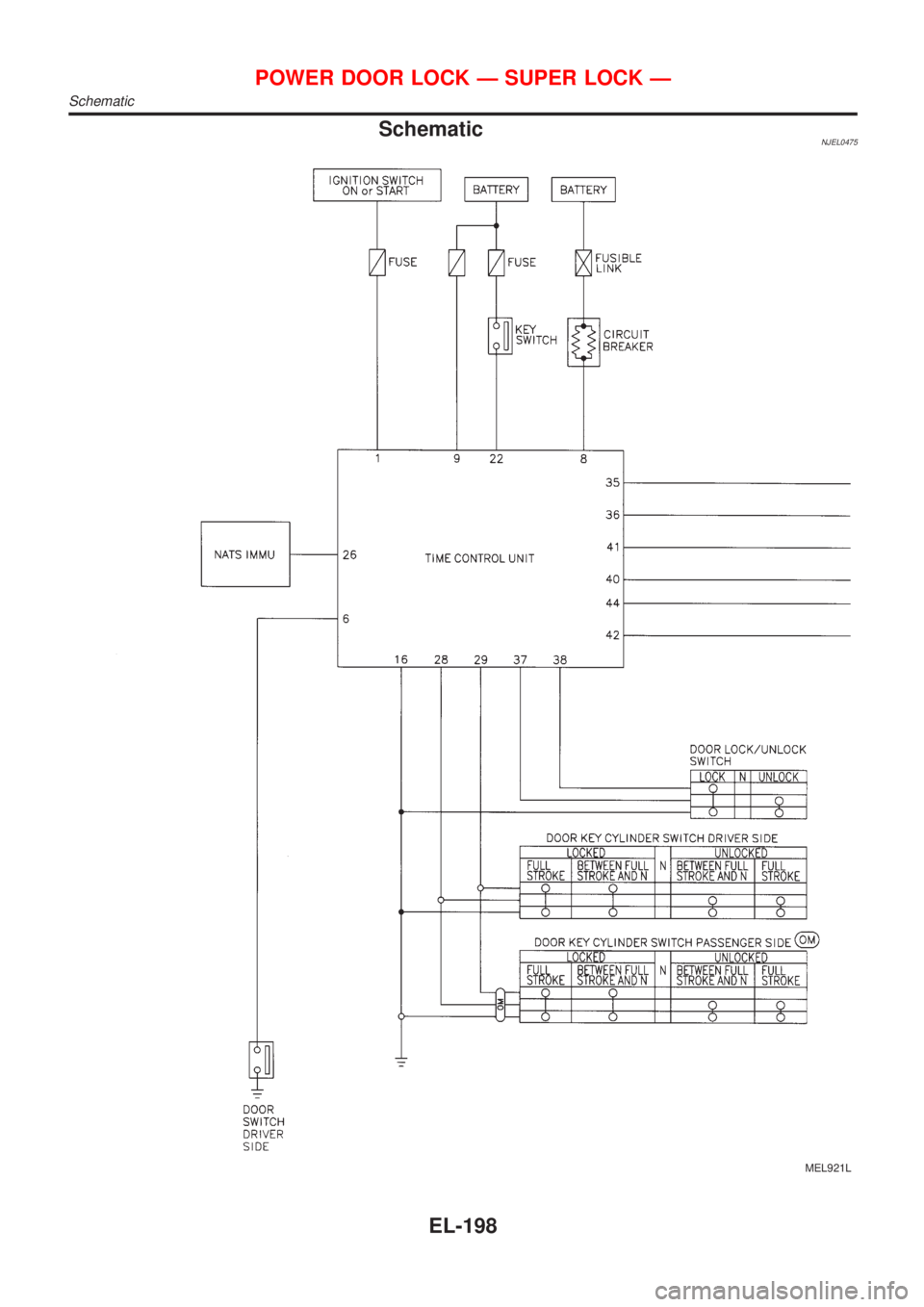
SchematicNJEL0475
MEL921L
POWER DOOR LOCK Ð SUPER LOCK Ð
Schematic
EL-198
Trending: child seat, towing, abs warning lamp, brake fluid, Cooling system, Fuel, Tail
