NISSAN ALMERA N16 2001 Electronic Repair Manual
Manufacturer: NISSAN, Model Year: 2001, Model line: ALMERA N16, Model: NISSAN ALMERA N16 2001Pages: 2493, PDF Size: 66.97 MB
Page 631 of 2493
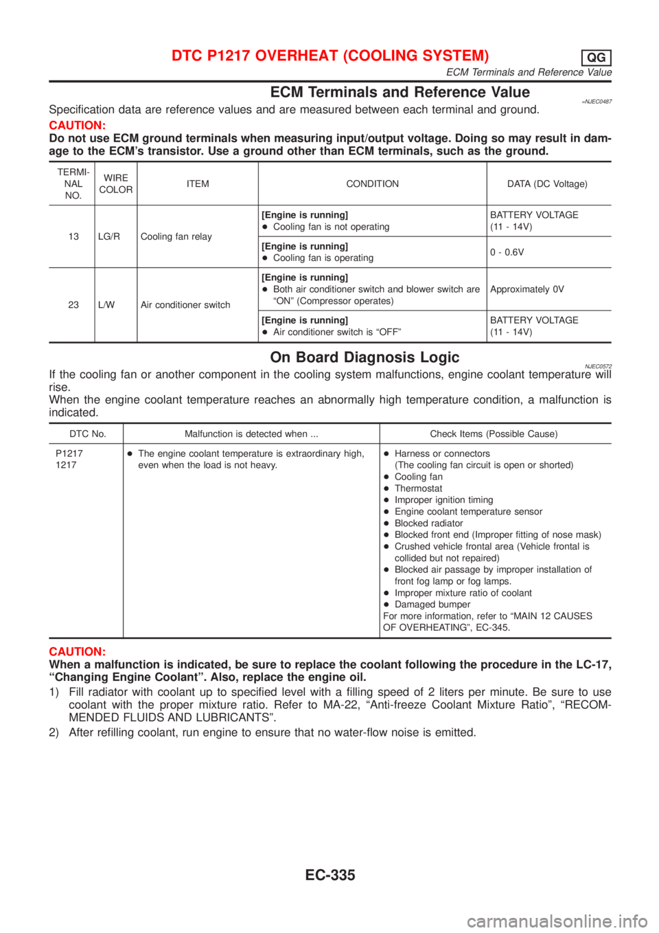
ECM Terminals and Reference Value=NJEC0487Specification data are reference values and are measured between each terminal and ground.
CAUTION:
Do not use ECM ground terminals when measuring input/output voltage. Doing so may result in dam-
age to the ECM's transistor. Use a ground other than ECM terminals, such as the ground.
TERMI-
NAL
NO.WIRE
COLORITEM CONDITION DATA (DC Voltage)
13 LG/R Cooling fan relay[Engine is running]
+Cooling fan is not operatingBATTERY VOLTAGE
(11 - 14V)
[Engine is running]
+Cooling fan is operating0 - 0.6V
23 L/W Air conditioner switch[Engine is running]
+Both air conditioner switch and blower switch are
ªONº (Compressor operates)Approximately 0V
[Engine is running]
+Air conditioner switch is ªOFFºBATTERY VOLTAGE
(11 - 14V)
On Board Diagnosis LogicNJEC0572If the cooling fan or another component in the cooling system malfunctions, engine coolant temperature will
rise.
When the engine coolant temperature reaches an abnormally high temperature condition, a malfunction is
indicated.
DTC No. Malfunction is detected when ... Check Items (Possible Cause)
P1217
1217+The engine coolant temperature is extraordinary high,
even when the load is not heavy.+Harness or connectors
(The cooling fan circuit is open or shorted)
+Cooling fan
+Thermostat
+Improper ignition timing
+Engine coolant temperature sensor
+Blocked radiator
+Blocked front end (Improper fitting of nose mask)
+Crushed vehicle frontal area (Vehicle frontal is
collided but not repaired)
+Blocked air passage by improper installation of
front fog lamp or fog lamps.
+Improper mixture ratio of coolant
+Damaged bumper
For more information, refer to ªMAIN 12 CAUSES
OF OVERHEATINGº, EC-345.
CAUTION:
When a malfunction is indicated, be sure to replace the coolant following the procedure in the LC-17,
ªChanging Engine Coolantº. Also, replace the engine oil.
1) Fill radiator with coolant up to specified level with a filling speed of 2 liters per minute. Be sure to use
coolant with the proper mixture ratio. Refer to MA-22, ªAnti-freeze Coolant Mixture Ratioº, ªRECOM-
MENDED FLUIDS AND LUBRICANTSº.
2) After refilling coolant, run engine to ensure that no water-flow noise is emitted.
DTC P1217 OVERHEAT (COOLING SYSTEM)QG
ECM Terminals and Reference Value
EC-335
Page 632 of 2493
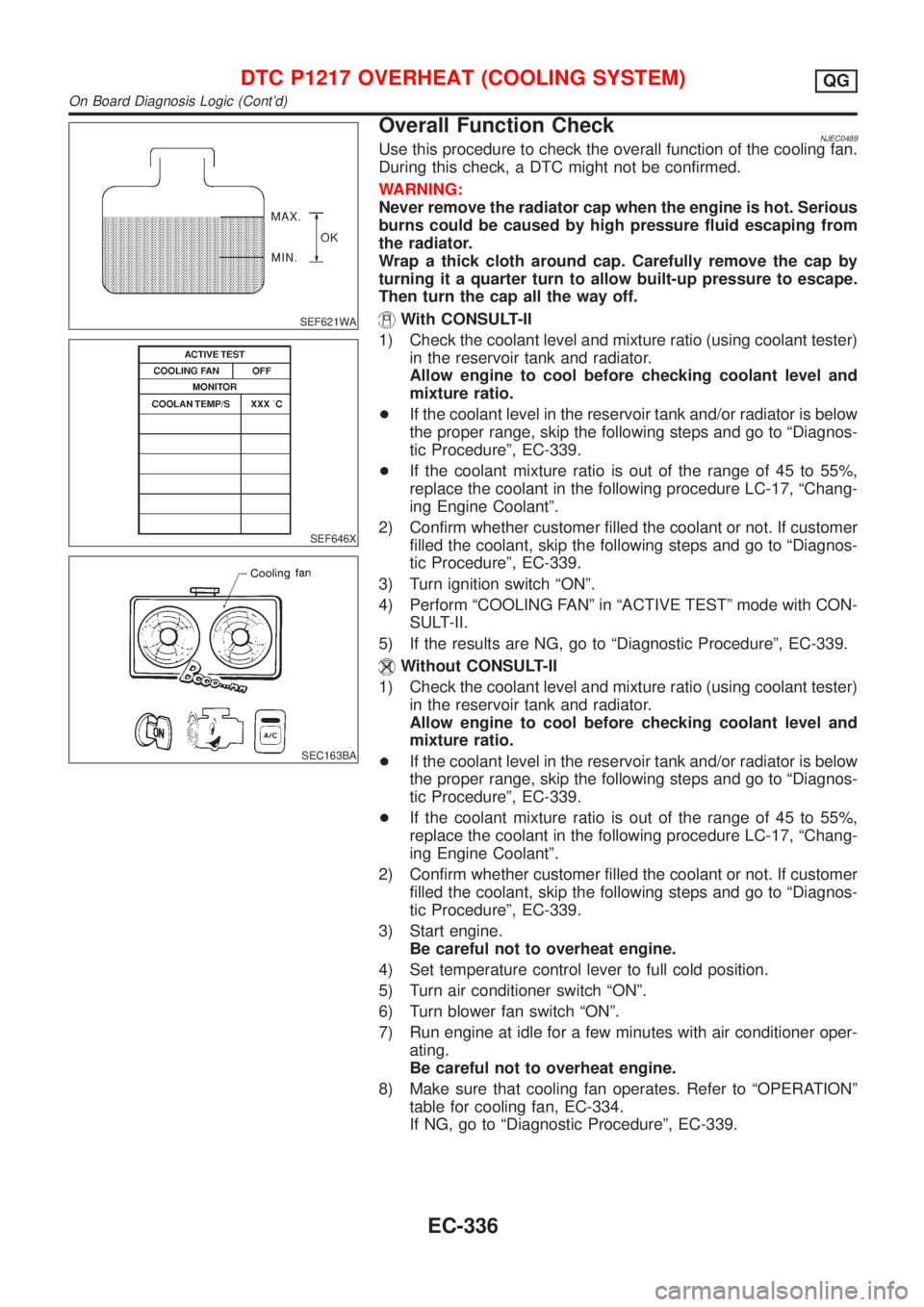
SEF621WA
SEF646X
SEC163BA
Overall Function CheckNJEC0489Use this procedure to check the overall function of the cooling fan.
During this check, a DTC might not be confirmed.
WARNING:
Never remove the radiator cap when the engine is hot. Serious
burns could be caused by high pressure fluid escaping from
the radiator.
Wrap a thick cloth around cap. Carefully remove the cap by
turning it a quarter turn to allow built-up pressure to escape.
Then turn the cap all the way off.
With CONSULT-II
1) Check the coolant level and mixture ratio (using coolant tester)
in the reservoir tank and radiator.
Allow engine to cool before checking coolant level and
mixture ratio.
+If the coolant level in the reservoir tank and/or radiator is below
the proper range, skip the following steps and go to ªDiagnos-
tic Procedureº, EC-339.
+If the coolant mixture ratio is out of the range of 45 to 55%,
replace the coolant in the following procedure LC-17, ªChang-
ing Engine Coolantº.
2) Confirm whether customer filled the coolant or not. If customer
filled the coolant, skip the following steps and go to ªDiagnos-
tic Procedureº, EC-339.
3) Turn ignition switch ªONº.
4) Perform ªCOOLING FANº in ªACTIVE TESTº mode with CON-
SULT-II.
5) If the results are NG, go to ªDiagnostic Procedureº, EC-339.
Without CONSULT-II
1) Check the coolant level and mixture ratio (using coolant tester)
in the reservoir tank and radiator.
Allow engine to cool before checking coolant level and
mixture ratio.
+If the coolant level in the reservoir tank and/or radiator is below
the proper range, skip the following steps and go to ªDiagnos-
tic Procedureº, EC-339.
+If the coolant mixture ratio is out of the range of 45 to 55%,
replace the coolant in the following procedure LC-17, ªChang-
ing Engine Coolantº.
2) Confirm whether customer filled the coolant or not. If customer
filled the coolant, skip the following steps and go to ªDiagnos-
tic Procedureº, EC-339.
3) Start engine.
Be careful not to overheat engine.
4) Set temperature control lever to full cold position.
5) Turn air conditioner switch ªONº.
6) Turn blower fan switch ªONº.
7) Run engine at idle for a few minutes with air conditioner oper-
ating.
Be careful not to overheat engine.
8) Make sure that cooling fan operates. Refer to ªOPERATIONº
table for cooling fan, EC-334.
If NG, go to ªDiagnostic Procedureº, EC-339.
DTC P1217 OVERHEAT (COOLING SYSTEM)QG
On Board Diagnosis Logic (Cont'd)
EC-336
Page 633 of 2493
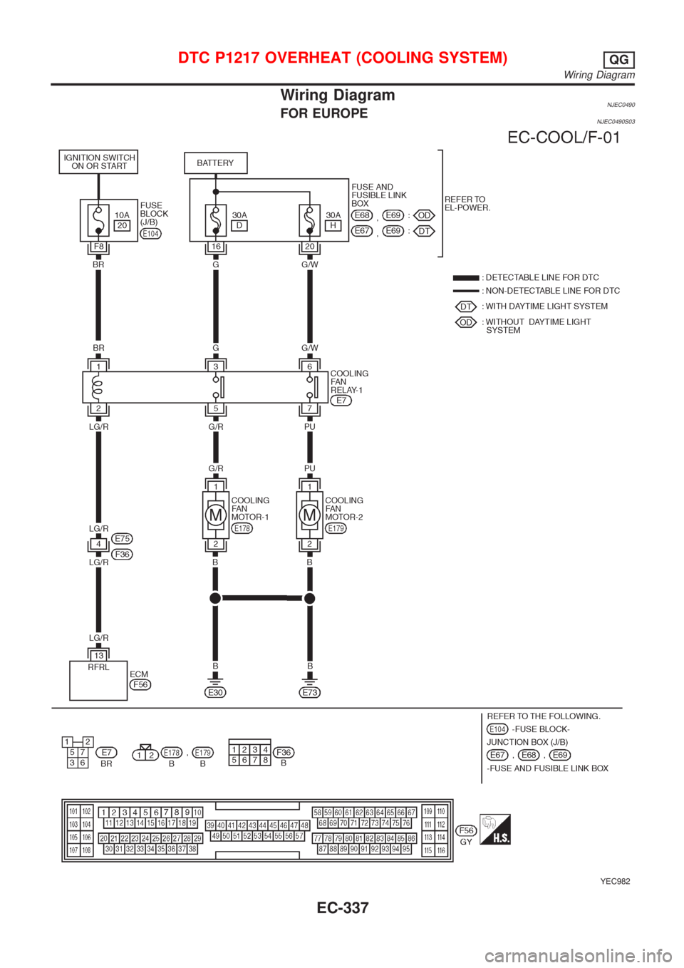
Wiring DiagramNJEC0490FOR EUROPENJEC0490S03
YEC982
DTC P1217 OVERHEAT (COOLING SYSTEM)QG
Wiring Diagram
EC-337
Page 634 of 2493
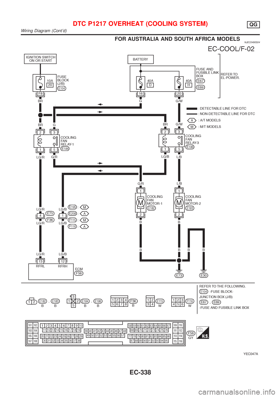
FOR AUSTRALIA AND SOUTH AFRICA MODELSNJEC0490S04
YEC047A
DTC P1217 OVERHEAT (COOLING SYSTEM)QG
Wiring Diagram (Cont'd)
EC-338
Page 635 of 2493
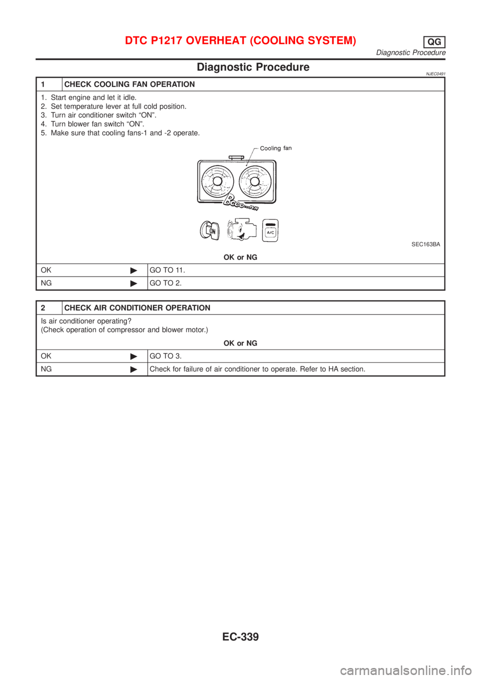
Diagnostic ProcedureNJEC0491
1 CHECK COOLING FAN OPERATION
1. Start engine and let it idle.
2. Set temperature lever at full cold position.
3. Turn air conditioner switch ªONº.
4. Turn blower fan switch ªONº.
5. Make sure that cooling fans-1 and -2 operate.
SEC163BA
OK or NG
OK©GO TO 11.
NG©GO TO 2.
2 CHECK AIR CONDITIONER OPERATION
Is air conditioner operating?
(Check operation of compressor and blower motor.)
OK or NG
OK©GO TO 3.
NG©Check for failure of air conditioner to operate. Refer to HA section.
DTC P1217 OVERHEAT (COOLING SYSTEM)QG
Diagnostic Procedure
EC-339
Page 636 of 2493
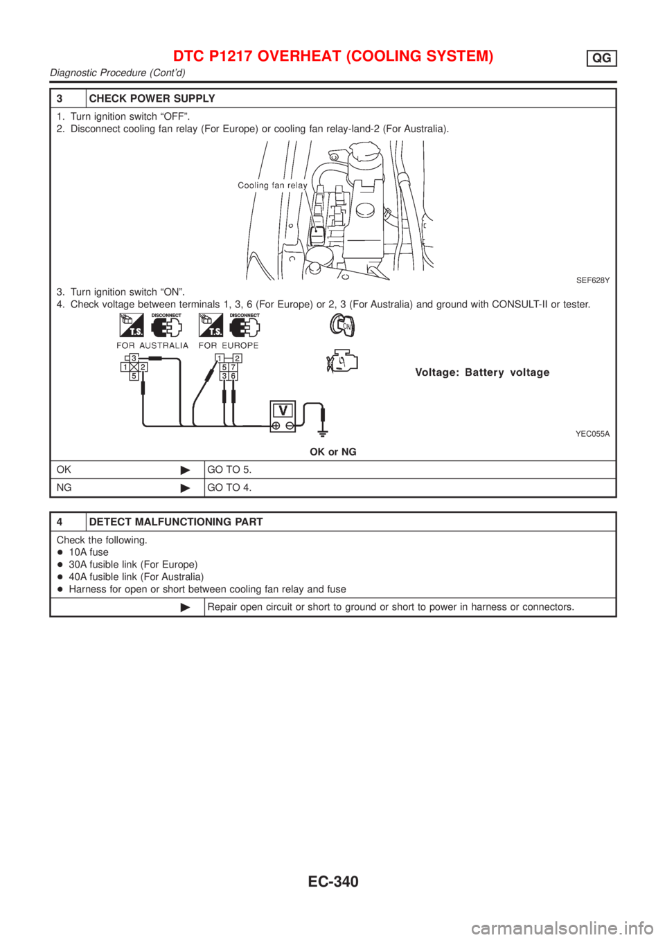
3 CHECK POWER SUPPLY
1. Turn ignition switch ªOFFº.
2. Disconnect cooling fan relay (For Europe) or cooling fan relay-land-2 (For Australia).
SEF628Y
3. Turn ignition switch ªONº.
4. Check voltage between terminals 1, 3, 6 (For Europe) or 2, 3 (For Australia) and ground with CONSULT-II or tester.
YEC055A
OK or NG
OK©GO TO 5.
NG©GO TO 4.
4 DETECT MALFUNCTIONING PART
Check the following.
+10A fuse
+30A fusible link (For Europe)
+40A fusible link (For Australia)
+Harness for open or short between cooling fan relay and fuse
©Repair open circuit or short to ground or short to power in harness or connectors.
DTC P1217 OVERHEAT (COOLING SYSTEM)QG
Diagnostic Procedure (Cont'd)
EC-340
Page 637 of 2493
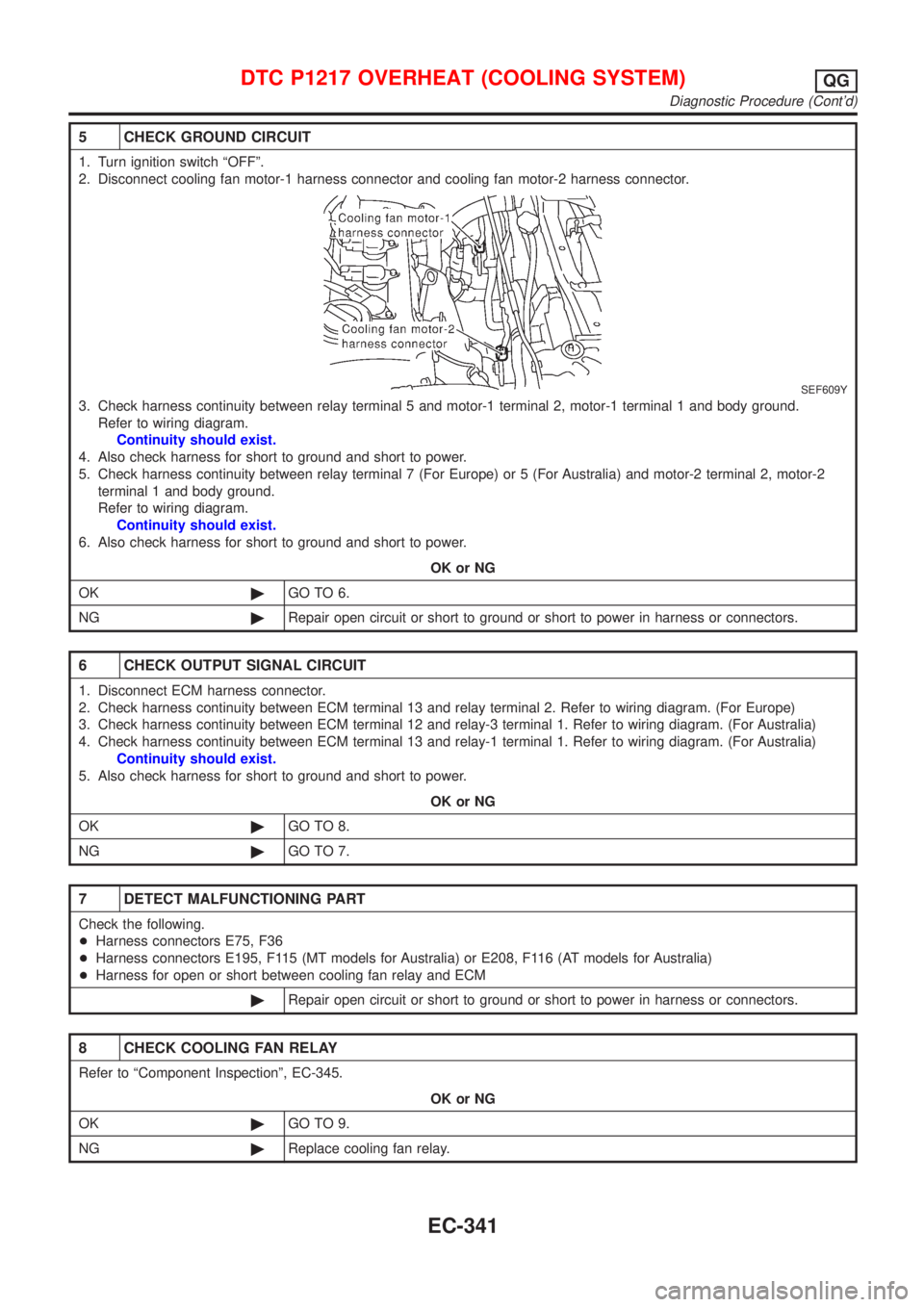
5 CHECK GROUND CIRCUIT
1. Turn ignition switch ªOFFº.
2. Disconnect cooling fan motor-1 harness connector and cooling fan motor-2 harness connector.
SEF609Y
3. Check harness continuity between relay terminal 5 and motor-1 terminal 2, motor-1 terminal 1 and body ground.
Refer to wiring diagram.
Continuity should exist.
4. Also check harness for short to ground and short to power.
5. Check harness continuity between relay terminal 7 (For Europe) or 5 (For Australia) and motor-2 terminal 2, motor-2
terminal 1 and body ground.
Refer to wiring diagram.
Continuity should exist.
6. Also check harness for short to ground and short to power.
OK or NG
OK©GO TO 6.
NG©Repair open circuit or short to ground or short to power in harness or connectors.
6 CHECK OUTPUT SIGNAL CIRCUIT
1. Disconnect ECM harness connector.
2. Check harness continuity between ECM terminal 13 and relay terminal 2. Refer to wiring diagram. (For Europe)
3. Check harness continuity between ECM terminal 12 and relay-3 terminal 1. Refer to wiring diagram. (For Australia)
4. Check harness continuity between ECM terminal 13 and relay-1 terminal 1. Refer to wiring diagram. (For Australia)
Continuity should exist.
5. Also check harness for short to ground and short to power.
OK or NG
OK©GO TO 8.
NG©GO TO 7.
7 DETECT MALFUNCTIONING PART
Check the following.
+Harness connectors E75, F36
+Harness connectors E195, F115 (MT models for Australia) or E208, F116 (AT models for Australia)
+Harness for open or short between cooling fan relay and ECM
©Repair open circuit or short to ground or short to power in harness or connectors.
8 CHECK COOLING FAN RELAY
Refer to ªComponent Inspectionº, EC-345.
OK or NG
OK©GO TO 9.
NG©Replace cooling fan relay.
DTC P1217 OVERHEAT (COOLING SYSTEM)QG
Diagnostic Procedure (Cont'd)
EC-341
Page 638 of 2493
9 CHECK COOLING FAN MOTORS-1 AND -2
Refer to ªComponent Inspectionº, EC-345.
OK or NG
OK©GO TO 10.
NG©Replace cooling fan motors.
10 CHECK INTERMITTENT INCIDENT
Perform ªTROUBLE DIAGNOSIS FOR INTERMITTENT INCIDENTº, EC-144.
©INSPECTION END
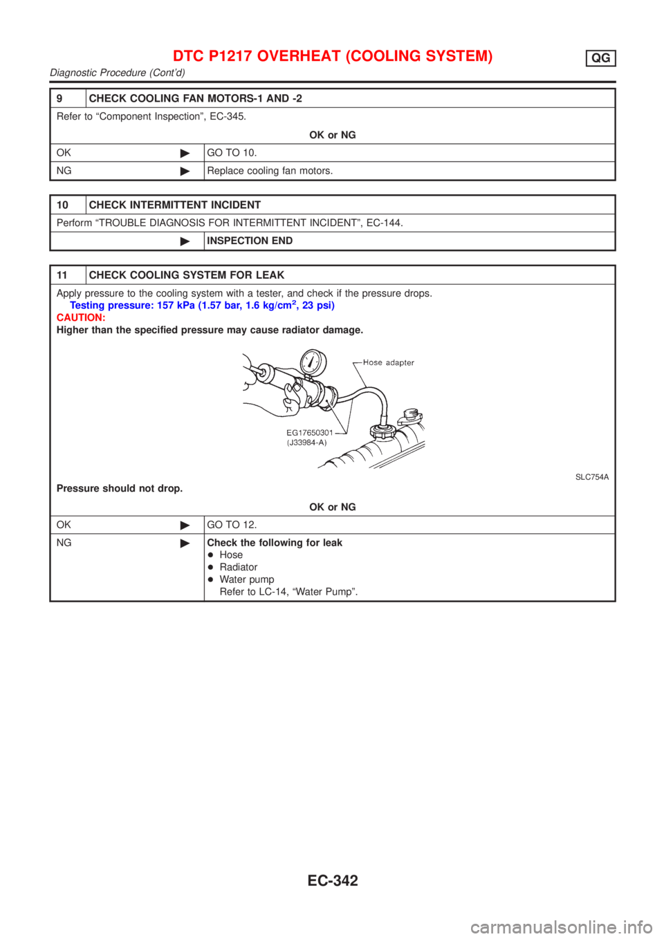
11 CHECK COOLING SYSTEM FOR LEAK
Apply pressure to the cooling system with a tester, and check if the pressure drops.
Testing pressure: 157 kPa (1.57 bar, 1.6 kg/cm2, 23 psi)
CAUTION:
Higher than the specified pressure may cause radiator damage.
SLC754A
Pressure should not drop.
OK or NG
OK©GO TO 12.
NG©Check the following for leak
+Hose
+Radiator
+Water pump
Refer to LC-14, ªWater Pumpº.
DTC P1217 OVERHEAT (COOLING SYSTEM)QG
Diagnostic Procedure (Cont'd)
EC-342
Page 639 of 2493
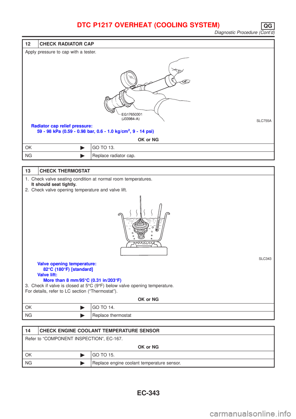
12 CHECK RADIATOR CAP
Apply pressure to cap with a tester.
SLC755A
Radiator cap relief pressure:
59 - 98 kPa (0.59 - 0.98 bar, 0.6 - 1.0 kg/cm2,9-14psi)
OK or NG
OK©GO TO 13.
NG©Replace radiator cap.
13 CHECK THERMOSTAT
1. Check valve seating condition at normal room temperatures.
It should seat tightly.
2. Check valve opening temperature and valve lift.
SLC343
Valve opening temperature:
82ÉC (180ÉF) [standard]
Valve lift:
More than 8 mm/95ÉC (0.31 in/203ÉF)
3. Check if valve is closed at 5ÉC (9ÉF) below valve opening temperature.
For details, refer to LC section (ªThermostatº).
OK or NG
OK©GO TO 14.
NG©Replace thermostat
14 CHECK ENGINE COOLANT TEMPERATURE SENSOR
Refer to ªCOMPONENT INSPECTIONº, EC-167.
OK or NG
OK©GO TO 15.
NG©Replace engine coolant temperature sensor.
DTC P1217 OVERHEAT (COOLING SYSTEM)QG
Diagnostic Procedure (Cont'd)
EC-343
Page 640 of 2493

15 CHECK MAIN 12 CAUSES
If the cause cannot be isolated, go to ªMAIN 12 CAUSES OF OVERHEATINGº, EC-345.
©INSPECTION END
DTC P1217 OVERHEAT (COOLING SYSTEM)QG
Diagnostic Procedure (Cont'd)
EC-344