Time NISSAN ALMERA N16 2003 Electronic User Guide
[x] Cancel search | Manufacturer: NISSAN, Model Year: 2003, Model line: ALMERA N16, Model: NISSAN ALMERA N16 2003Pages: 3189, PDF Size: 54.76 MB
Page 124 of 3189
![NISSAN ALMERA N16 2003 Electronic User Guide EM-46
[QG]
CAMSHAFT
●Thickness of new adjusting shim is indicated with stamped
mark on its back.
10. Install selected adjusting shim to valve lifter.
CAUTION:
Install shim with its stamp mar](/img/5/57350/w960_57350-123.png "NISSAN ALMERA N16 2003 Electronic User Guide EM-46
[QG]
CAMSHAFT
●Thickness of new adjusting shim is indicated with stamped
mark on its back.
10. Install selected adjusting shim to valve lifter.
CAUTION:
Install shim with its stamp mar")
EM-46
[QG]
CAMSHAFT
●Thickness of new adjusting shim is indicated with stamped
mark on its back.
10. Install selected adjusting shim to valve lifter.
CAUTION:
Install shim with its stamp mark facing the valve lifter.
11. Using camshaft pliers (special service tool), compress valve spring to remove lifter stopper (special ser-
vice tool).
12. Turn crankshaft a couple of times by hand.
13. Check that valve clearance is within standards.
Stamped mark Thickness of shim
200
202
:
:
2982.00 mm (0.0787 in)
2.02 mm (0.0795 in)
:
:
2.98 mm (0.1173 in)
Setting of adjusting shim thickness (at factory)
: Thickness 2.00 to 2.98 mm (0.0787 - 0.1173 in) [spacing of 0.02 mm (0.0008 in)] 50 types
MBIB0230E
Page 129 of 3189
![NISSAN ALMERA N16 2003 Electronic User Guide TIMING CHAIN
EM-51
[QG]
C
D
E
F
G
H
I
J
K
L
MA
EM
30. Remove timing chain, timing chain slack guide and tension guide.
31. Remove crankshaft sprocket.
INSPECTION AFTER REMOVAL
Timing Chain
Check timi](/img/5/57350/w960_57350-128.png "NISSAN ALMERA N16 2003 Electronic User Guide TIMING CHAIN
EM-51
[QG]
C
D
E
F
G
H
I
J
K
L
MA
EM
30. Remove timing chain, timing chain slack guide and tension guide.
31. Remove crankshaft sprocket.
INSPECTION AFTER REMOVAL
Timing Chain
Check timi")
TIMING CHAIN
EM-51
[QG]
C
D
E
F
G
H
I
J
K
L
MA
EM
30. Remove timing chain, timing chain slack guide and tension guide.
31. Remove crankshaft sprocket.
INSPECTION AFTER REMOVAL
Timing Chain
Check timing chain for cracks or serious wear. If a malfunction is
detected, replace it.
INSTALLATION
CAUTION:
●Use a scraper to completely remove all liquid gasket adhering to mounting surface. De-grease and
clean with white gasoline.
●After installation, wipe off any protruding liquid gasket.
1. Install timing chain and its related parts with the following procedure:
●For aligning positions for each sprocket and timing chain, and
installed condition of their related parts, refer to figure.
●Install each sprocket with its mating mark facing engine front
side.
a. Install timing chain and crankshaft sprocket.
●Make sure that crankshaft key points straight up (No.1 cylin-
der is at TDC).
●Hook timing chain on front end of camshaft so that it will not
fall off.
b. Install timing chain slack guide and tension guide.
c. Install camshaft sprocket. Refer to EM-35, "
INSTALLATION" .
d. Install chain tensioner. Refer to EM-35, "
INSTALLATION" .
e. Make sure again that mating marks are properly aligned.
f. Temporarily install oil pump drive spacer, crankshaft pulley, and crankshaft pulley mounting bolt so that
crankshaft can be rotated.
g. Rotate crankshaft clockwise several times to make sure it rotates normally. Refer to EM-35, "
INSTALLA-
TION" .
h. Rotate crankshaft clockwise several times, and check that there is no unusual condition.
i. Remove parts temporarily installed in step f.
PBIC0282E
KBIA1398E
Page 130 of 3189
![NISSAN ALMERA N16 2003 Electronic User Guide EM-52
[QG]
TIMING CHAIN
2. Install front oil seal to front cover.
●Install it so that identification letters on oil seal will face toward
front side of the engine.
●Using an oil seal drift (commer](/img/5/57350/w960_57350-129.png "NISSAN ALMERA N16 2003 Electronic User Guide EM-52
[QG]
TIMING CHAIN
2. Install front oil seal to front cover.
●Install it so that identification letters on oil seal will face toward
front side of the engine.
●Using an oil seal drift (commer")
EM-52
[QG]
TIMING CHAIN
2. Install front oil seal to front cover.
●Install it so that identification letters on oil seal will face toward
front side of the engine.
●Using an oil seal drift (commercial service tool), press oil seal
in until it is flush with end surface of mounting position.
●Make sure that oil seal outer circumference is free from dam-
age and burr.
3. Install front cover with the following procedure:
a. Install O-ring to cylinder block.
b. Using a flat-bladed screwdriver, apply a continuous bead of liq-
uid gasket to contact surface between cylinder head gasket
lower surface and cylinder block (2 locations shown in figure).
Use Genuine Liquid Gasket or equivalent.
c. Apply a continuous bead of liquid gasket to back surface of front
cover (location shown in figure).
CAUTION:
●Do not apply liquid gasket to groove A shown in figure.
●Especially for locations indicated by * mark in figure,
strictly observe application range of liquid gasket.
d. Apply liquid gasket to top surface of front cover lightly and
evenly.
Use Genuine Liquid Gasket or equivalent.
e. Install O-ring to back surface of front cover.
f. With socket of oil pump inner rotor placed on crankshaft top sur-
face (clearance between front cover top surface and cylinder
head gasket lower surface is secured), move front cover close to
cylinder block. (Right side in figure)
g. Lift front cover at an angle and install it to mounting position so
that front cover will come in contact with both cylinder head gas-
ket lower surface and cylinder block front surface at the same
time. (Right side in figure)
CAUTION:
●During work, be sure not to damage cylinder head gas-
ket.
●When installing, avoid discontinuous bead of liquid gas-
ket caused by allowing it to adhere to an unnecessary area.
PBIC0530E
PBIC0561E
PBIC0562E
PBIC0563E
Page 143 of 3189
![NISSAN ALMERA N16 2003 Electronic User Guide CYLINDER HEAD
EM-65
[QG]
C
D
E
F
G
H
I
J
K
L
MA
EM
2. Ream cylinder head recess diameter for service valve seat.
●Be sure to ream in circles concentric to the valve guide center.
●This will enable](/img/5/57350/w960_57350-142.png "NISSAN ALMERA N16 2003 Electronic User Guide CYLINDER HEAD
EM-65
[QG]
C
D
E
F
G
H
I
J
K
L
MA
EM
2. Ream cylinder head recess diameter for service valve seat.
●Be sure to ream in circles concentric to the valve guide center.
●This will enable")
CYLINDER HEAD
EM-65
[QG]
C
D
E
F
G
H
I
J
K
L
MA
EM
2. Ream cylinder head recess diameter for service valve seat.
●Be sure to ream in circles concentric to the valve guide center.
●This will enable valve seat to fit correctly.
3. Heat cylinder head to 110 to 130°C (230 to 266°F) by soaking in
heated oil.
4. Provide valve seats cooled well with dry ice. Force fit valve seat
into cylinder head.
CAUTION:
●Avoid directly to touching cold valve seats.
●Cylinder head contains heat. When working, wear protec-
tive equipment to avoid getting burned.
5. Using valve seat cutter set (commercial service tool) or valve
seat grinder, finish the seat to the specified dimensions.
CAUTION:
When using valve seat cutter, firmly grip the cutter handle
with both hands. Then, press on the contacting surface all
around the circumference to cut in a single drive. Improper
pressure on with the cutter or cutting many different times
may result in stage valve seat.Oversize [0.5 mm (0.020 in)]:
Intake : 31.5 mm (1.240 in)
Exhaust : 26.5 mm (1.043 in)
SEM795A
SEM008A
PBIC0579E
SEM934C
Page 156 of 3189
![NISSAN ALMERA N16 2003 Electronic User Guide EM-78
[QG]
CYLINDER BLOCK
14. Tighten connecting rod nuts with the following procedure.
a. Lubricate connecting rod bolts and seat of nuts with new engine
oil.
b. Tighten to a torque of 13.72 - 1](/img/5/57350/w960_57350-155.png "NISSAN ALMERA N16 2003 Electronic User Guide EM-78
[QG]
CYLINDER BLOCK
14. Tighten connecting rod nuts with the following procedure.
a. Lubricate connecting rod bolts and seat of nuts with new engine
oil.
b. Tighten to a torque of 13.72 - 1")
EM-78
[QG]
CYLINDER BLOCK
14. Tighten connecting rod nuts with the following procedure.
a. Lubricate connecting rod bolts and seat of nuts with new engine
oil.
b. Tighten to a torque of 13.72 - 15.68 N·m (1.4 - 1.5 kg-m, 10.2 -
11.5 ft-lb)
c. Turn all nuts another 35 to 40 degrees (Target: 35 degrees).
CAUTION:
Always use angle wrench (special service tool). Avoid tight-
ening based on visual check alone.
●After tightening nuts, make sure that crankshaft rotates
smoothly.
●Check connecting rod side clearance. Refer to EM-84, "CONNECTING ROD SIDE CLEARANCE" .
15. Install rear oil seal.
●Use an oil seal drift (commercial service tool) to press it in. At
this time, be careful not to cause any scratches or burrs on
circumference of oil seal.
●Press oil seal into rear oil seal retainer until it does not project
from end.
16. Install rear oil seal retainer.
●Apply continuous bead of liquid gasket to parts shown in fig-
ure.
●Install rear oil seal retainer by aligning it with dowel pins on
cylinder block.
17. Install rear plate.
SEM943F
SEM897A
PBIC0589E
AEM248
Page 168 of 3189
![NISSAN ALMERA N16 2003 Electronic User Guide EM-90
[QG]
CYLINDER BLOCK
3. Cut cylinder bores.
●When any cylinder needs boring, all other cylinders must also be bored.
●Do not cut too much out of cylinder bore at a time. Cut only 0.05 mm (0.0](/img/5/57350/w960_57350-167.png "NISSAN ALMERA N16 2003 Electronic User Guide EM-90
[QG]
CYLINDER BLOCK
3. Cut cylinder bores.
●When any cylinder needs boring, all other cylinders must also be bored.
●Do not cut too much out of cylinder bore at a time. Cut only 0.05 mm (0.0")
EM-90
[QG]
CYLINDER BLOCK
3. Cut cylinder bores.
●When any cylinder needs boring, all other cylinders must also be bored.
●Do not cut too much out of cylinder bore at a time. Cut only 0.05 mm (0.0020 in) or so in diameter
at a time.
4. Hone cylinders to obtain specified piston-to-bore clearance.
5. Measure finished cylinder bore for out-of-round and taper.
●Measurement should be done after cylinder bore cools down.
OUTER DIAMETER OF CRANKSHAFT JOURNAL
●Measure outer diameter of crankshaft journals.
OUTER DIAMETER OF CRANKSHAFT PIN
●Measure outer diameter of crankshaft pin.
OUT-OF-ROUND AND TAPER OF CRANKSHAFT
●Using a micrometer, measure the dimensions at 4 different
points shown in the figure on each journal and pin.
●Out-of-round is indicated by the difference in dimensions
between A and B at 1 and 2.
●Taper is indicated by the difference in dimension between 1 and
2 at A and B.
CRANKSHAFT RUNOUT
●Place a V-block on a precise flat table to support the journals on
the both end of the crankshaft.
●Place a dial gauge straight up on the No. 3 journal.
●While rotating the crankshaft, read the movement of the pointer
on the dial gauge. (Total indicator reading)Standard : 49.940 - 49.964 mm (1.9661 - 1.9671 in) dia.
Standard : 39.956 - 39.974 mm (1.5731 - 1.5738 in) dia.
PBIC0270E
Limit:
Out-of-round (A – B) : 0.005 mm (0.0002 in)
Taper (1 – 2) : 0.005 mm (0.0002 in)
PBIC0614E
Limit: : 0.10 mm (0.004 in)
PBIC0271E
Page 182 of 3189
![NISSAN ALMERA N16 2003 Electronic User Guide EM-104
[QG]
SERVICE DATA AND SPECIFICATIONS (SDS)
CONNECTING ROD BEARING
Standard Size
Unit: mm (in)
Undersize
Unit: mm (in)
Bearing Clearance
Unit: mm (in)
MISCELLANEOUS COMPONENTS
Unit: mm (in)
*: T](/img/5/57350/w960_57350-181.png "NISSAN ALMERA N16 2003 Electronic User Guide EM-104
[QG]
SERVICE DATA AND SPECIFICATIONS (SDS)
CONNECTING ROD BEARING
Standard Size
Unit: mm (in)
Undersize
Unit: mm (in)
Bearing Clearance
Unit: mm (in)
MISCELLANEOUS COMPONENTS
Unit: mm (in)
*: T")
EM-104
[QG]
SERVICE DATA AND SPECIFICATIONS (SDS)
CONNECTING ROD BEARING
Standard Size
Unit: mm (in)
Undersize
Unit: mm (in)
Bearing Clearance
Unit: mm (in)
MISCELLANEOUS COMPONENTS
Unit: mm (in)
*: Total indicator reading
Tightening TorqueEBS00LQQ
*1: Parts to be tightened in particular orders.
1)-: Order of tightening when tightening two or more times separately.
Unit: N·m (kg-m, ft-lb) / Unit: N·m (kg-m, in-lb)*2
Grade No. Thickness Identification color or number
0 1.503 - 1.506 (0.0592 - 0.0593) Block
1 1.506 - 1.509 (0.0593 - 0.0594) Red
2 1.509 - 1.512 (0.0594 - 0.0595) Green
Grade No. Thickness Identification color or number
0.08 (0.0031) 1.542 - 1.546 (0.0607 - 0.0609) —
0.12 (0.0047) 1.562 - 1.566 (0.0615 - 0.0617) —
0.25 (0.0098) 1.627 - 1.631 (0.0641 - 0.0642) —
Connecting rod bearing clear-
anceStandard 0.014 - 0.039 (0.0006 - 0.0015)
Limit 0.1 (0.004)
Flywheel runout [TIR*] Less than 0.1 (0.004)
Camshaft sprocket runout [TIR*] Less than 0.15 (0.0059)
Mass air flow sensor
8.4 - 10.8 (0.9 - 1.1, 75 - 95)*2
Resonator
3.8 - 4.5 (0.39 - 0.45, 34 - 39)*2
Air cleaner case lower
3.8 - 4.5 (0.39 - 0.46, 34 - 39)*2
Intake manifold16.7 - 23.5 (1.7 - 2.4, 13 - 17)
Intake manifold collector
7.0 - 9.5 (0.71 - 0.97, 62 - 84)*
2
Intake manifold support 16.7 - 23.5 (1.7 - 2.4, 13 - 17)
Electric throttle control actuator 17.7 - 21.6 (1.8 - 2.2, 13 - 15)
Exhaust manifold25.5 - 29.4 (2.6 - 2.9, 19 - 21)
Exhaust manifold cover
6.3 - 8.3 (0.64 - 0.85, 56 - 73)*
2
Heated oxygen sensor 58.8 - 78.4 (6.0 - 7.9, 44 - 57)
Ground nut79.4 (8.1, 59)
Oil pan
6.28 - 8.34 (0.64 - 0.85, 56 - 73)*
2
Oil pan drain plug29.4 - 39.2 ( 3.0 - 3.9, 22 - 28)
Oil strainer
6.28 - 8.34 (0.64 - 0.85, 56 - 73)*
2
Ignition coil
3.8 - 5.0 (0.38 - 0.51, 33 - 44)*2
Spark plug19.6 - 29.4 (2.0 - 3.0, 15 - 21)
*1 Fuel tube1) 11.8 - 13.8 (1.2 - 1.4, 9 - 10 )
2) 17 - 23 (1.7 - 2.4, 13 - 17)
Rocker cover
6.9 - 9.5 (0.70 - 0.97, 61 - 84)*
2
Page 192 of 3189
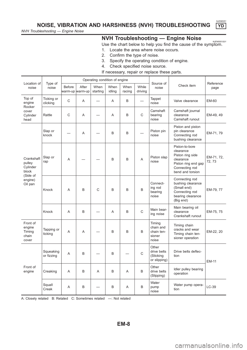
NJEM0051
NVH Troubleshooting — Engine NoiseNJEM0051S01Use the chart below to help you find the cause of the symptom.
1. Locate the area where noise occurs.
2. Confirm the type of noise.
3. Specify the operating condition of engine.
4. Check specified noise source.
If necessary, repair or replace these parts.
Location of
noiseTy p e o f
noiseOperating condition of engine
Source of
noiseCheck itemReference
page Before
warm-upAfter
warm-upWhen
startingWhen
idlingWhen
racingWhile
driving
To p o f
engine
Rocker
cover
Cylinder
headTicking or
clickingC A—A B—Tappet
noiseValve clearance EM-60
Rattle C A — A B CCamshaft
bearing
noiseCamshaft journal
clearance
Camshaft runoutEM-49, 49
Crankshaft
pulley
Cylinder
block
(Side of
engine)
Oil panSlap or
knock—A—B B—Piston pin
noisePiston and piston
pin clearance
Connecting rod
bushing clearanceEM-71, 79
Slap or
rapA——B B APiston slap
noisePiston-to-bore
clearance
Piston ring side
clearance
Piston ring end gap
Connecting rod
bend and torsionEM-71, 72,
72, 73
Knock A B C B B BConnect-
ing rod
bearing
noiseConnecting rod
bushing clearance
(Small end)
Connecting rod
bearing clearance
(Big end)EM-79, 77
Knock A B — A B CMain bear-
ing noiseMain bearing oil
clearance
Crankshaft runoutEM-75, 75
Front of
engine
Timing
chain
coverTapping or
tickingAA—BBBTiming
chain and
chain ten-
sioner
noiseTiming chain
cracks and wear
Timing chain ten-
sioner operationEM-22, 20
Front of
engineSqueaking
or fizzingA B—B—COther
drive belts
(Sticking
or slipping)Drive belts deflec-
tion
EM-11
CreakingABABABOther
drive belts
(Slipping)Idler pulley bearing
operation
Squall
CreakAB—BABWater
pump
noiseWater pump opera-
tionLC-39
A: Closely related B: Related C: Sometimes related —: Not related
NOISE, VIBRATION AND HARSHNESS (NVH) TROUBLESHOOTINGYD
NVH Troubleshooting — Engine Noise
EM-8
Page 226 of 3189
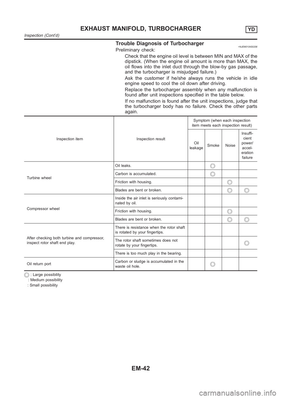
Trouble Diagnosis of Turbocharger=NJEM0104S0206Preliminary check:
Check that the engine oil level is between MIN and MAX of the
dipstick. (When the engine oil amount is more than MAX, the
oil flows into the inlet duct through the blow-by gas passage,
and the turbocharger is misjudged failure.)
Ask the customer if he/she always runs the vehicle in idle
engine speed to cool the oil down after driving.
Replace the turbocharger assembly when any malfunction is
found after unit inspections specified in the table below.
If no malfunction is found after the unit inspections, judge that
the turbocharger body has no failure. Check the other parts
again.
Inspection item Inspection resultSymptom (when each inspection
item meets each inspection result)
Oil
leakageSmoke NoiseInsuffi-
cient
power/
accel-
eration
failure
Turbine wheelOil leaks.
Carbon is accumulated.
Friction with housing.
Blades are bent or broken.
Compressor wheelInside the air inlet is seriously contami-
nated by oil.
Friction with housing.
Blades are bent or broken.
After checking both turbine and compressor,
inspect rotor shaft end play.There is resistance when the rotor shaft
is rotated by your fingertips.
The rotor shaft sometimes does not
rotate by your fingertips.
There is too much play in the bearing.
Oil return portCarbon or sludge is accumulated in the
waste oil hole.
: Large possibility
: Medium possibility
: Small possibility
EXHAUST MANIFOLD, TURBOCHARGERYD
Inspection (Cont’d)
EM-42
Page 237 of 3189
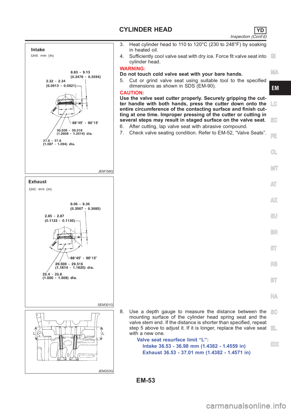
JEM158G
SEM301G
3. Heat cylinder head to 110 to 120°C (230 to 248°F) by soaking
in heated oil.
4. Sufficiently cool valve seat with dry ice. Force fit valve seat into
cylinder head.
WARNING:
Do not touch cold valve seat with your bare hands.
5. Cut or grind valve seat using suitable tool to the specified
dimensions as shown in SDS (EM-90).
CAUTION:
Use the valve seat cutter properly. Securely gripping the cut-
ter handle with both hands, press the cutter down onto the
entire circumference of the contacting surface and finish cut-
ting at one time. Improper pressing of the cutter or cutting in
several steps may result in staged surface on the valve seat.
6. After cutting, lap valve seat with abrasive compound.
7. Check valve seating condition. Refer to EM-52, “Valve Seats”.
JEM253G
8. Use a depth gauge to measure the distance between the
mounting surface of the cylinder head spring seat and the
valve stem end. If the distance is shorter than specified, repeat
step 5 above to adjust it. If it is longer, replace the valve seat
with a new one.
Valve seat resurface limit “L”:
Intake 36.53 - 36.98 mm (1.4382 - 1.4559 in)
Exhaust 36.53 - 37.01 mm (1.4382 - 1.4571 in)
GI
MA
LC
EC
FE
CL
MT
AT
AX
SU
BR
ST
RS
BT
HA
SC
EL
IDX
CYLINDER HEADYD
Inspection (Cont’d)
EM-53