NISSAN ALMERA N16 2003 Electronic Repair Manual
ALMERA N16 2003
NISSAN
NISSAN
https://www.carmanualsonline.info/img/5/57350/w960_57350-0.png
NISSAN ALMERA N16 2003 Electronic Repair Manual
Trending: cooling fan wiring diagram, towing, fuel cap, gauge, roof rack, fuel tank removal, jack points
Page 2481 of 3189
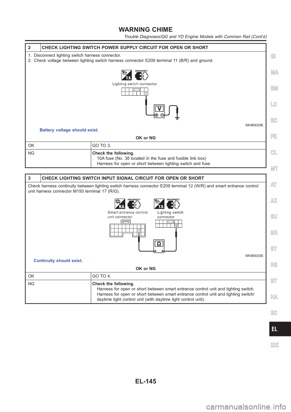
2 CHECK LIGHTING SWITCH POWER SUPPLY CIRCUIT FOR OPEN OR SHORT
1. Disconnect lighting switch harness connector.
2. Check voltage between lighting switch harness connector E209 terminal11 (B/R) and ground.
MKIB0029E
Battery voltage should exist.
OK or NG
OK GO TO 3.
NGCheck the following.
10A fuse (No. 38 located in the fuse and fusible link box)
Harness for open or short between lighting switch and fuse
3 CHECK LIGHTING SWITCH INPUT SIGNAL CIRCUIT FOR OPEN OR SHORT
Check harness continuity between lighting switch harness connector E209terminal 12 (W/R) and smart entrance control
unit harness connector M193 terminal 17 (R/G).
MKIB0030E
Continuity should exist.
OK or NG
OK GO TO 4.
NGCheck the following.
Harness for open or short between smart entrance control unit and lightingswitch.
Harness for open or short between smart entrance control unit and lightingswitch/
daytime light control unit (with daytime light control unit).
GI
MA
EM
LC
EC
FE
CL
MT
AT
AX
SU
BR
ST
RS
BT
HA
SC
IDX
WARNING CHIME
Trouble Diagnoses/QG and YD Engine Models with Common Rail (Cont’d)
EL-145
Page 2482 of 3189
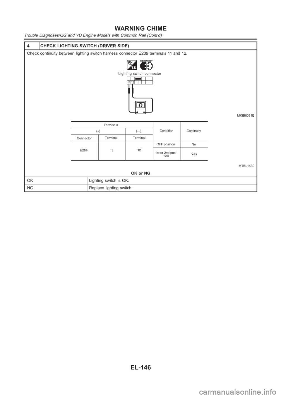
4 CHECK LIGHTING SWITCH (DRIVER SIDE)
Check continuity between lighting switch harness connector E209 terminals 11 and 12.
MKIB0031E
MTBL1439
OK or NG
OK Lighting switch is OK.
NG Replace lighting switch.
WARNING CHIME
Trouble Diagnoses/QG and YD Engine Models with Common Rail (Cont’d)
EL-146
Page 2483 of 3189
KEY SWITCH INSERT SIGNAL CHECKNJEL0551S05
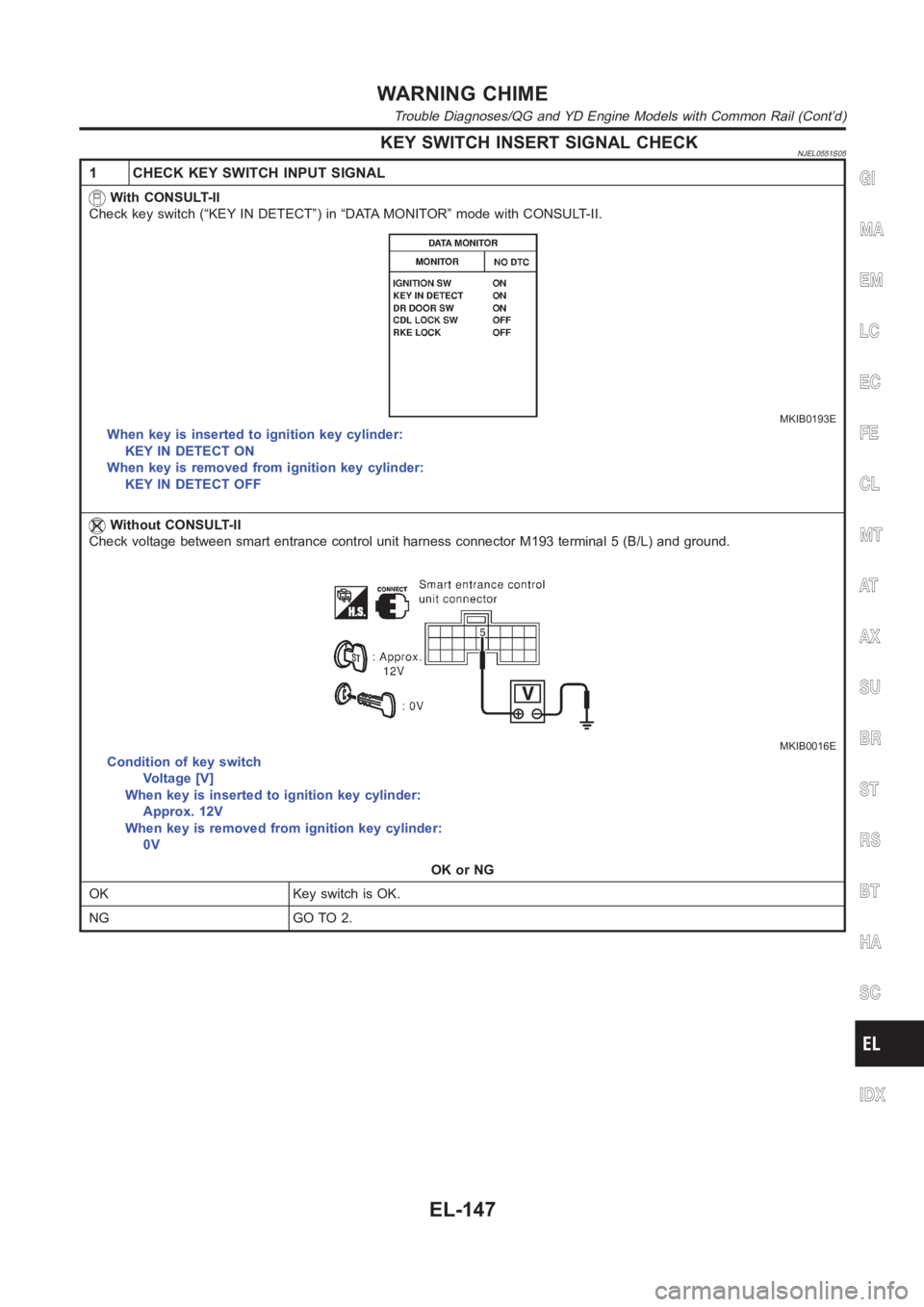
1 CHECK KEY SWITCH INPUT SIGNAL
With CONSULT-II
Check key switch (“KEY IN DETECT”) in “DATA MONITOR” mode with CONSULT-II.
MKIB0193E
When key is inserted to ignition key cylinder:
KEY IN DETECT ON
When key is removed from ignition key cylinder:
KEY IN DETECT OFF
Without CONSULT-II
Check voltage between smart entrance control unit harness connector M193terminal 5 (B/L) and ground.
MKIB0016E
Condition of key switch
Voltage [V]
When key is inserted to ignition key cylinder:
Approx. 12V
When key is removed from ignition key cylinder:
0V
OK or NG
OK Key switch is OK.
NG GO TO 2.
GI
MA
EM
LC
EC
FE
CL
MT
AT
AX
SU
BR
ST
RS
BT
HA
SC
IDX
WARNING CHIME
Trouble Diagnoses/QG and YD Engine Models with Common Rail (Cont’d)
EL-147
Page 2484 of 3189
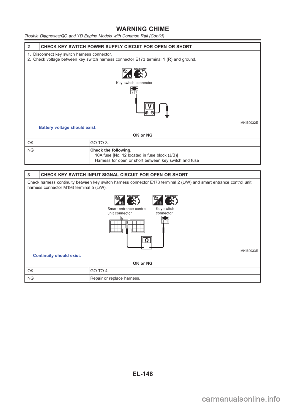
2 CHECK KEY SWITCH POWER SUPPLY CIRCUIT FOR OPEN OR SHORT
1. Disconnect key switch harness connector.
2. Check voltage between key switch harness connector E173 terminal 1 (R) and ground.
MKIB0032E
Battery voltage should exist.
OK or NG
OK GO TO 3.
NGCheck the following.
10A fuse [No. 12 located in fuse block (J/B)]
Harness for open or short between key switch and fuse
3 CHECK KEY SWITCH INPUT SIGNAL CIRCUIT FOR OPEN OR SHORT
Check harness continuity between key switch harness connector E173 terminal 2 (L/W) and smart entrance control unit
harness connector M193 terminal 5 (L/W).
MKIB0033E
Continuity should exist.
OK or NG
OK GO TO 4.
NG Repair or replace harness.
WARNING CHIME
Trouble Diagnoses/QG and YD Engine Models with Common Rail (Cont’d)
EL-148
Page 2485 of 3189
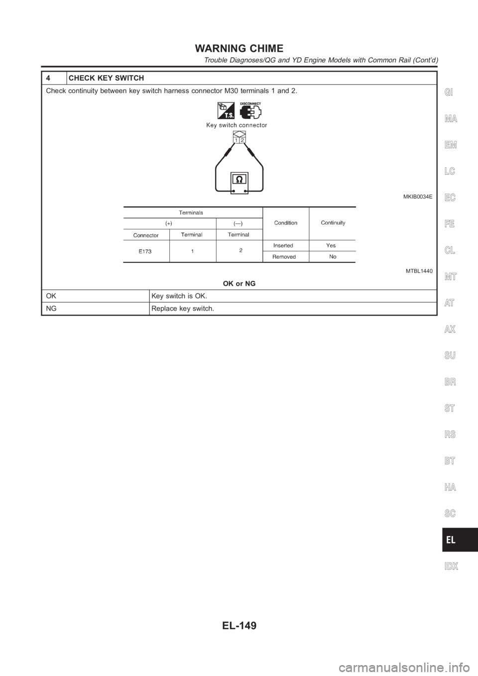
4 CHECK KEY SWITCH
Check continuity between key switch harness connector M30 terminals 1 and2.
MKIB0034E
MTBL1440
OK or NG
OK Key switch is OK.
NG Replace key switch.
GI
MA
EM
LC
EC
FE
CL
MT
AT
AX
SU
BR
ST
RS
BT
HA
SC
IDX
WARNING CHIME
Trouble Diagnoses/QG and YD Engine Models with Common Rail (Cont’d)
EL-149
Page 2486 of 3189
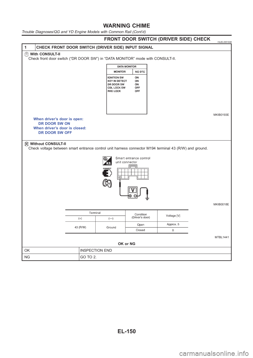
FRONT DOOR SWITCH (DRIVER SIDE) CHECK=NJEL0551S06
1 CHECK FRONT DOOR SWITCH (DRIVER SIDE) INPUT SIGNAL
With CONSULT-II
Check front door switch (“DR DOOR SW”) in “DATA MONITOR” mode with CONSULT-II.
MKIB0193E
When driver’s door is open:
DR DOOR SW ON
When driver’s door is closed:
DR DOOR SW OFF
Without CONSULT-II
Check voltage between smart entrance control unit harness connector M194terminal 43 (R/W) and ground.
MKIB0018E
MTBL1441
OK or NG
OK INSPECTION END
NG GO TO 2.
WARNING CHIME
Trouble Diagnoses/QG and YD Engine Models with Common Rail (Cont’d)
EL-150
Page 2487 of 3189
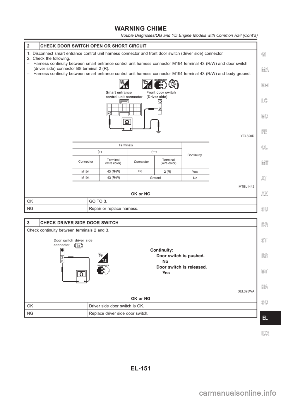
2 CHECK DOOR SWITCH OPEN OR SHORT CIRCUIT
1. Disconnect smart entrance control unit harness connector and front door switch (driver side) connector.
2. Check the following.
– Harness continuity between smart entrance control unit harness connector M194 terminal 43 (R/W) and door switch
(driver side) connector B8 terminal 2 (R).
– Harness continuity between smart entrance control unit harness connector M194 terminal 43 (R/W) and body ground.
YEL820D
MTBL1442
OK or NG
OK GO TO 3.
NG Repair or replace harness.
3 CHECK DRIVER SIDE DOOR SWITCH
Check continuity between terminals 2 and 3.
SEL325WA
OK or NG
OK Driver side door switch is OK.
NG Replace driver side door switch.
GI
MA
EM
LC
EC
FE
CL
MT
AT
AX
SU
BR
ST
RS
BT
HA
SC
IDX
WARNING CHIME
Trouble Diagnoses/QG and YD Engine Models with Common Rail (Cont’d)
EL-151
Page 2488 of 3189
Trouble Diagnoses/YD Engine Models without
Common Rail and K9K Engine Models
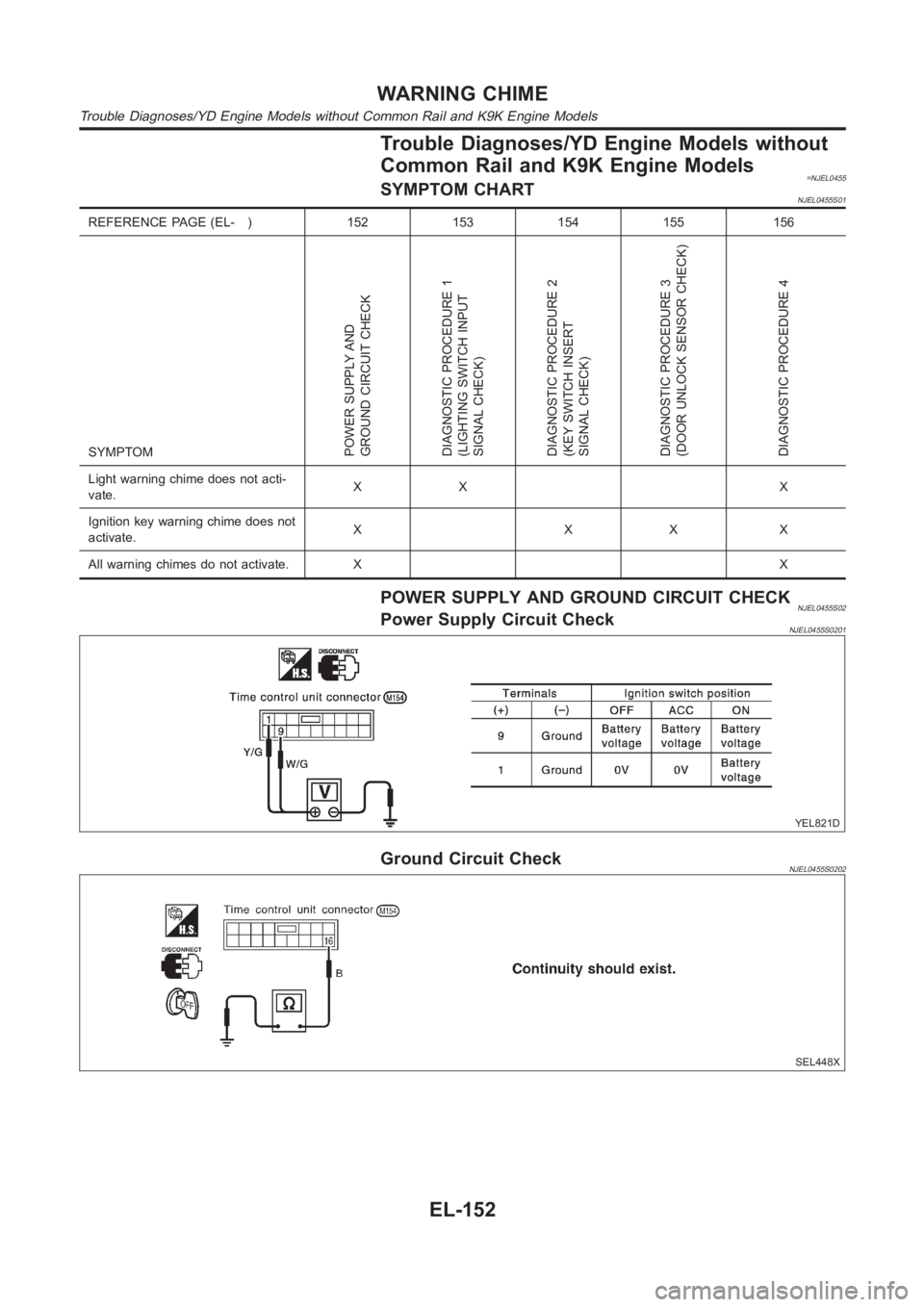
=NJEL0455SYMPTOM CHARTNJEL0455S01
REFERENCE PAGE (EL- ) 152 153 154 155 156
SYMPTOM
POWER SUPPLY AND
GROUND CIRCUIT CHECK
DIAGNOSTIC PROCEDURE 1
(LIGHTING SWITCH INPUT
SIGNAL CHECK)
DIAGNOSTIC PROCEDURE 2
(KEY SWITCH INSERT
SIGNAL CHECK)
DIAGNOSTIC PROCEDURE 3
(DOOR UNLOCK SENSOR CHECK)
DIAGNOSTIC PROCEDURE 4
Light warning chime does not acti-
vate.XX X
Ignition key warning chime does not
activate.XXXX
All warning chimes do not activate. XX
POWER SUPPLY AND GROUND CIRCUIT CHECKNJEL0455S02Power Supply Circuit CheckNJEL0455S0201
YEL821D
Ground Circuit CheckNJEL0455S0202
SEL448X
WARNING CHIME
Trouble Diagnoses/YD Engine Models without Common Rail and K9K Engine Models
EL-152
Page 2489 of 3189
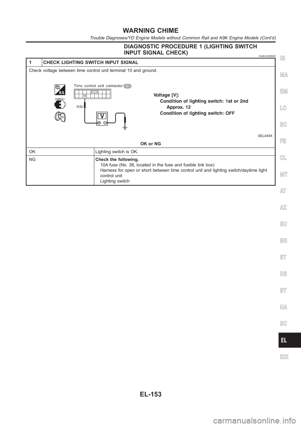
DIAGNOSTIC PROCEDURE 1 (LIGHTING SWITCH
INPUT SIGNAL CHECK)
=NJEL0455S03
1 CHECK LIGHTING SWITCH INPUT SIGNAL
Check voltage between time control unit terminal 10 and ground.
SEL449X
OK or NG
OK Lighting switch is OK.
NGCheck the following.
10A fuse (No. 38, located in the fuse and fusible link box)
Harness for open or short between time control unit and lighting switch/daytime light
control unit
Lighting switch
GI
MA
EM
LC
EC
FE
CL
MT
AT
AX
SU
BR
ST
RS
BT
HA
SC
IDX
WARNING CHIME
Trouble Diagnoses/YD Engine Models without Common Rail and K9K Engine Models (Cont’d)
EL-153
Page 2490 of 3189
DIAGNOSTIC PROCEDURE 2 (KEY SWITCH INSERT
SIGNAL CHECK)
=NJEL0455S04
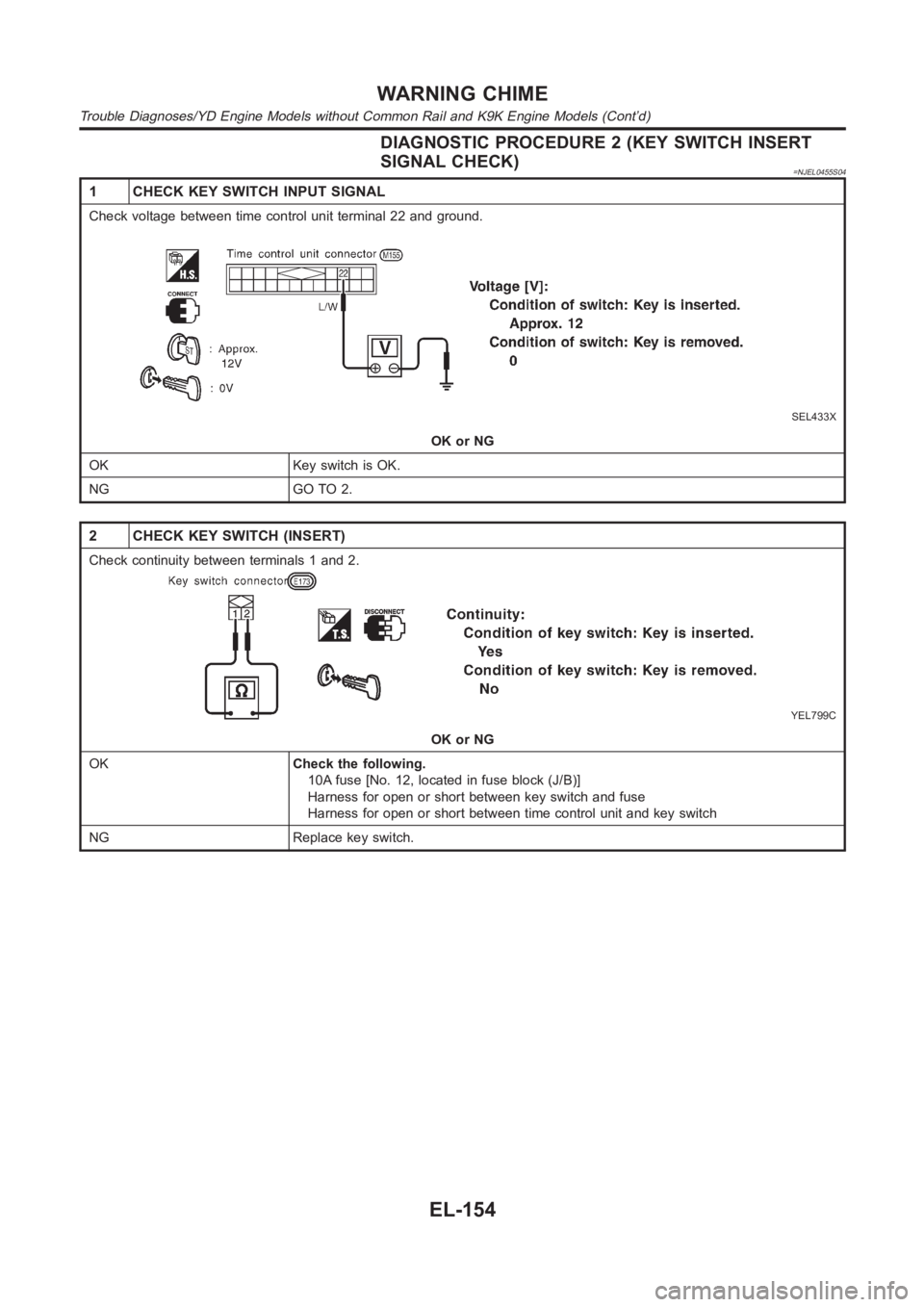
1 CHECK KEY SWITCH INPUT SIGNAL
Check voltage between time control unit terminal 22 and ground.
SEL433X
OK or NG
OK Key switch is OK.
NG GO TO 2.
2 CHECK KEY SWITCH (INSERT)
Check continuity between terminals 1 and 2.
YEL799C
OK or NG
OKCheck the following.
10A fuse [No. 12, located in fuse block (J/B)]
Harness for open or short between key switch and fuse
Harness for open or short between time control unit and key switch
NG Replace key switch.
WARNING CHIME
Trouble Diagnoses/YD Engine Models without Common Rail and K9K Engine Models (Cont’d)
EL-154
Trending: junction box b4, warning, Electrical systems, restraint, battery, refrigerant type, oil filter

