NISSAN ALMERA N16 2003 Electronic Repair Manual
ALMERA N16 2003
NISSAN
NISSAN
https://www.carmanualsonline.info/img/5/57350/w960_57350-0.png
NISSAN ALMERA N16 2003 Electronic Repair Manual
Trending: Engine control circuit, wheel, AIRBAG REMOVAL, ec 48, cooling fan, check transmission fluid, airbag off
Page 2441 of 3189
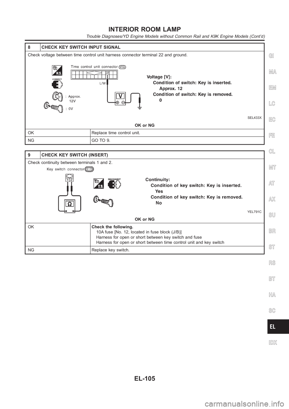
8 CHECK KEY SWITCH INPUT SIGNAL
Check voltage between time control unit harness connector terminal 22 andground.
SEL433X
OK or NG
OK Replace time control unit.
NG GO TO 9.
9 CHECK KEY SWITCH (INSERT)
Check continuity between terminals 1 and 2.
YEL791C
OK or NG
OKCheck the following.
10A fuse [No. 12, located in fuse block (J/B)]
Harness for open or short between key switch and fuse
Harness for open or short between time control unit and key switch
NG Replace key switch.
GI
MA
EM
LC
EC
FE
CL
MT
AT
AX
SU
BR
ST
RS
BT
HA
SC
IDX
INTERIOR ROOM LAMP
Trouble Diagnoses/YD Engine Models without Common Rail and K9K Engine Models (Cont’d)
EL-105
Page 2442 of 3189
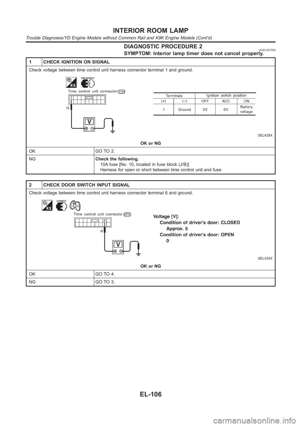
DIAGNOSTIC PROCEDURE 2=NJEL0437S02SYMPTOM: Interior lamp timer does not cancel properly.
1 CHECK IGNITION ON SIGNAL
Check voltage between time control unit harness connector terminal 1 and ground.
SEL429X
OK or NG
OK GO TO 2.
NGCheck the following.
10A fuse [No. 10, located in fuse block (J/B)]
Harness for open or short between time control unit and fuse
2 CHECK DOOR SWITCH INPUT SIGNAL
Check voltage between time control unit harness connector terminal 6 and ground.
SEL430X
OK or NG
OK GO TO 4.
NG GO TO 3.
INTERIOR ROOM LAMP
Trouble Diagnoses/YD Engine Models without Common Rail and K9K Engine Models (Cont’d)
EL-106
Page 2443 of 3189
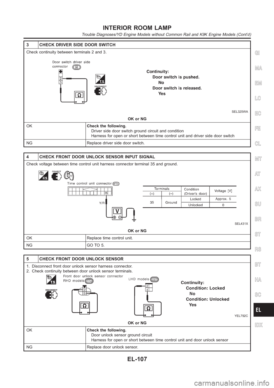
3 CHECK DRIVER SIDE DOOR SWITCH
Check continuity between terminals 2 and 3.
SEL325WA
OK or NG
OKCheck the following.
Driver side door switch ground circuit and condition
Harness for open or short between time control unit and driver side door switch
NG Replace driver side door switch.
4 CHECK FRONT DOOR UNLOCK SENSOR INPUT SIGNAL
Check voltage between time control unit harness connector terminal 35 andground.
SEL431X
OK or NG
OK Replace time control unit.
NG GO TO 5.
5 CHECK FRONT DOOR UNLOCK SENSOR
1. Disconnect front door unlock sensor harness connector.
2. Check continuity between door unlock sensor terminals.
YEL792C
OK or NG
OKCheck the following.
Door unlock sensor ground circuit
Harness for open or short between time control unit and door unlock sensor
NG Replace door unlock sensor.
GI
MA
EM
LC
EC
FE
CL
MT
AT
AX
SU
BR
ST
RS
BT
HA
SC
IDX
INTERIOR ROOM LAMP
Trouble Diagnoses/YD Engine Models without Common Rail and K9K Engine Models (Cont’d)
EL-107
Page 2444 of 3189
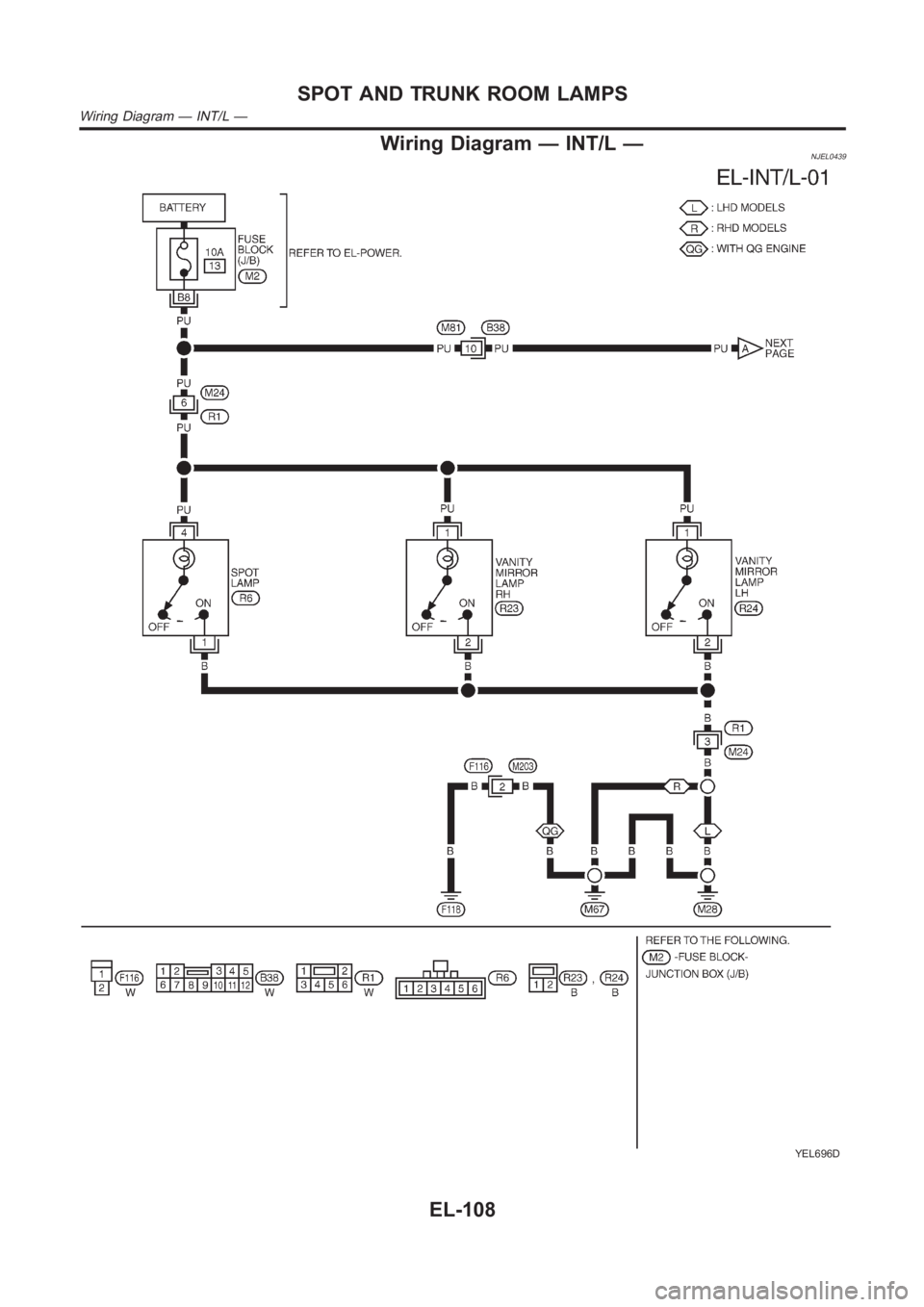
Wiring Diagram — INT/L —NJEL0439
YEL696D
SPOT AND TRUNK ROOM LAMPS
Wiring Diagram — INT/L —
EL-108
Page 2445 of 3189
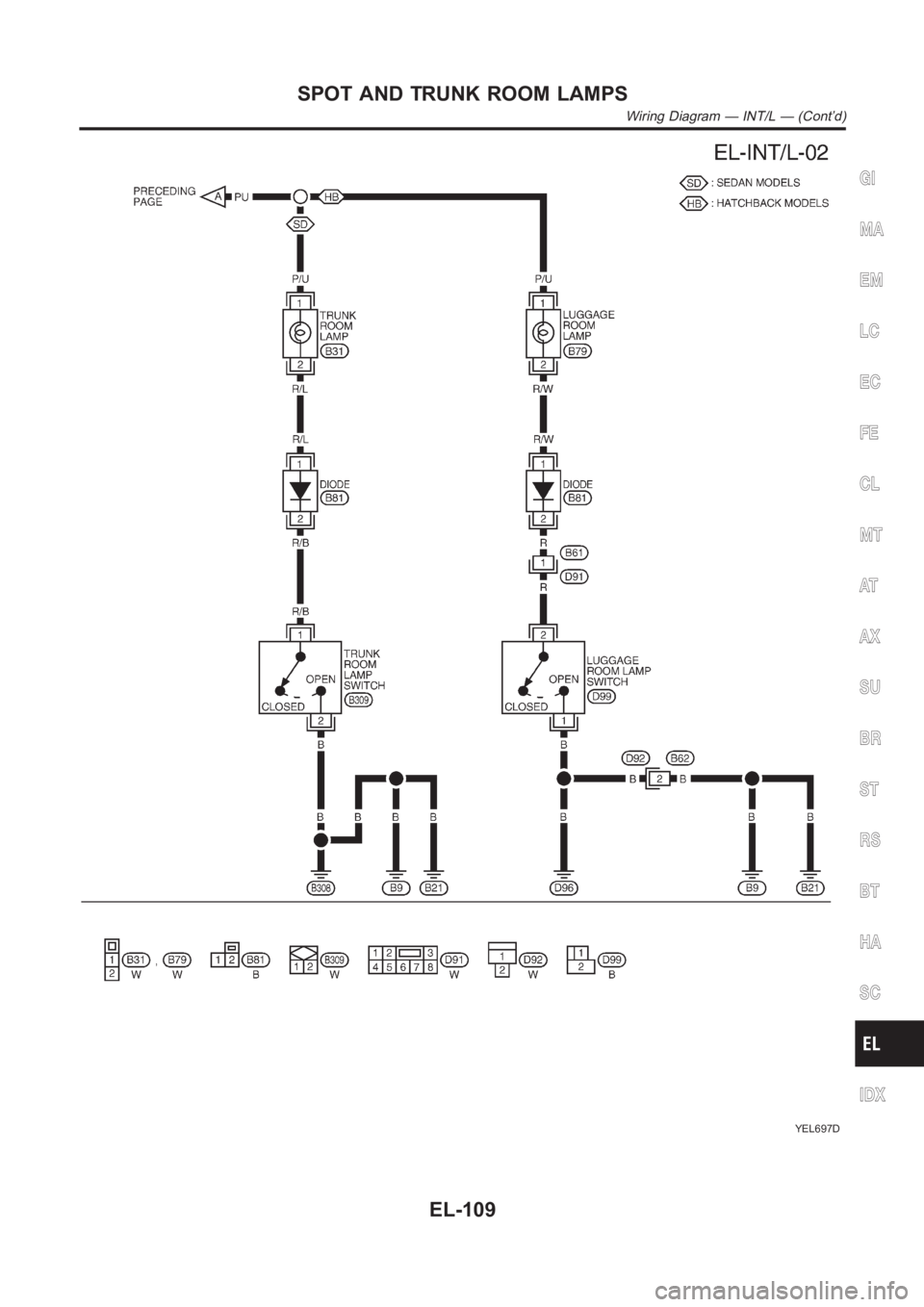
YEL697D
GI
MA
EM
LC
EC
FE
CL
MT
AT
AX
SU
BR
ST
RS
BT
HA
SC
IDX
SPOT AND TRUNK ROOM LAMPS
Wiring Diagram — INT/L — (Cont’d)
EL-109
Page 2446 of 3189
Component Parts and Harness Connector
Location
NJEL0441For details, refer to “ELECTRICAL UNIT LOCATION” (EL-543) and
“HARNESS LAYOUT” (EL-550).
System DescriptionNJEL0442UNIFIED CONTROL METERNJEL0442S01Speedometer, odo/trip meter, tachometer, fuel gauge and water temperature gauge are controlled totally
by control unit built-in combination meter.
Digital meter is adopted for odo/trip meter.*
*The record of the odo meter is kept even if the battery cable is disconnected. The record of the trip meter
is erased when the battery cable is disconnected.
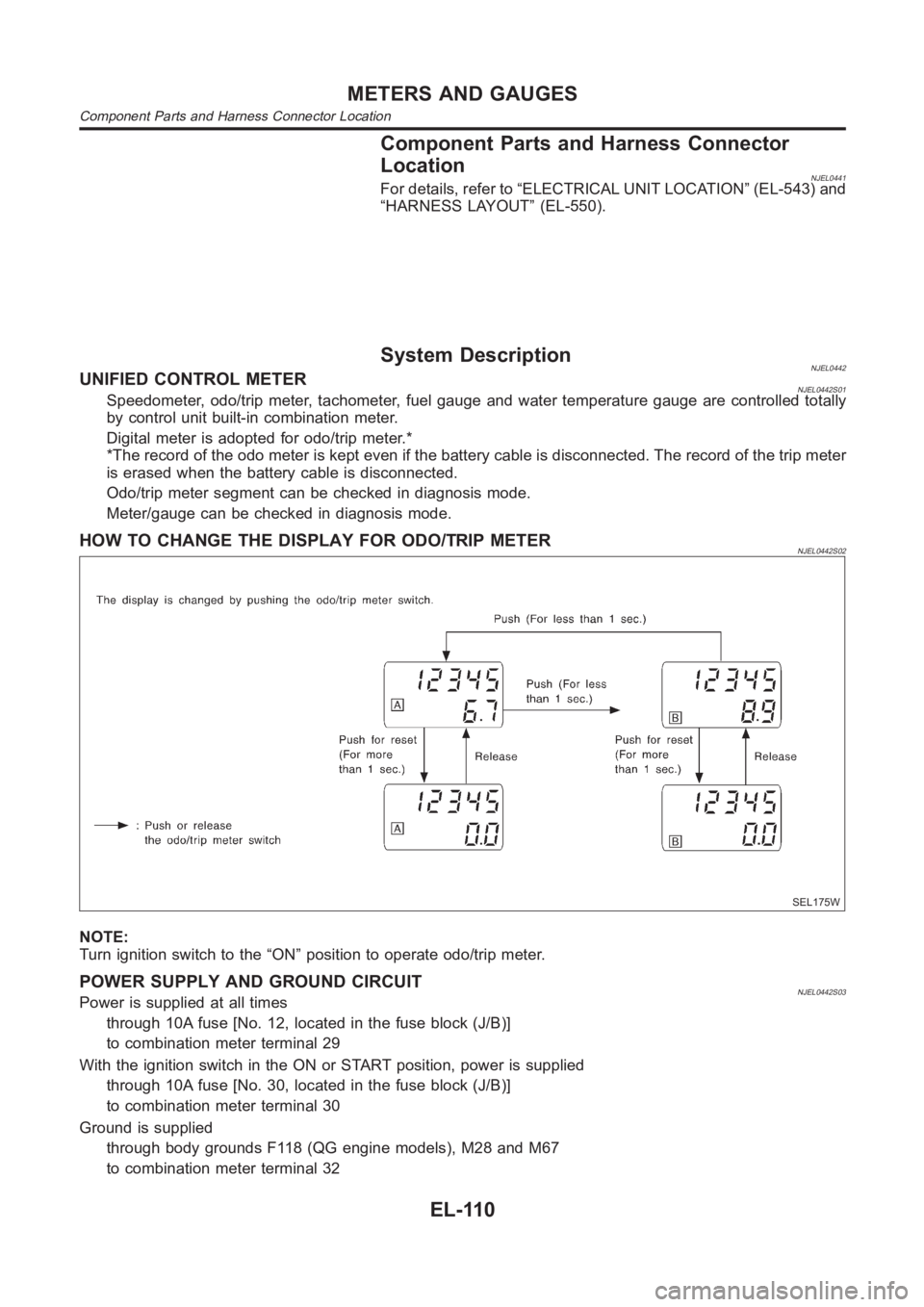
Odo/trip meter segment can be checked in diagnosis mode.
Meter/gauge can be checked in diagnosis mode.
HOW TO CHANGE THE DISPLAY FOR ODO/TRIP METERNJEL0442S02
SEL175W
NOTE:
Turn ignition switch to the “ON” position to operate odo/trip meter.
POWER SUPPLY AND GROUND CIRCUITNJEL0442S03Power is supplied at all times
through 10A fuse [No. 12, located in the fuse block (J/B)]
to combination meter terminal 29
With the ignition switch in the ON or START position, power is supplied
through 10A fuse [No. 30, located in the fuse block (J/B)]
to combination meter terminal 30
Ground is supplied
through body grounds F118 (QG engine models), M28 and M67
to combination meter terminal 32
METERS AND GAUGES
Component Parts and Harness Connector Location
EL-110
Page 2447 of 3189
WATER TEMPERATURE GAUGE (QG AND YD ENGINE MODELS WITH COMMON RAIL)NJEL0442S09The water temperature gauge indicates the engine coolant temperature.
ECM provides a engine coolant temperature signal to combination meter forwater temperature gauge with
CAN communication line.
WATER TEMPERATURE GAUGE (YD ENGINE MODELS WITHOUT COMMON RAIL)NJEL0442S04The water temperature gauge indicates the engine coolant temperature. The reading on the gauge is based
on the resistance of the thermal transmitter.
As the temperature of the coolant increases, the resistance of the thermaltransmitter decreases. A variable
ground is supplied to terminal 35 of the combination meter for the water temperature gauge. The needle on
the gauge moves from “C” to “H”.
TACHOMETER (QG AND YD ENGINE MODELS WITH COMMON RAIL)NJEL0442S10The tachometer indicates engine speed in revolution per minutes (rpm). ECM provides an engine speed sig-
nal to combination meter for tachometer with CAN communication line.
TACHOMETER (YD ENGINE MODELS WITHOUT COMMON RAIL)NJEL0442S05The tachometer indicates engine speed in revolutions per minute (rpm).
The tachometer is regulated by a signal
from terminal 32 (Gasoline engine models) or 439 (Diesel engine models) ofthe ECM
to combination meter terminal 53 for the tachometer.
FUEL GAUGENJEL0442S06The fuel gauge indicates the approximate fuel level in the fuel tank.
The fuel gauge is regulated by a variable ground signal supplied
from body grounds F118 (QG engine models), M28 and M67
through terminals 33 and 32 of combination meter,
through terminal 1 of the fuel level sensor unit and
through terminal 4 of the fuel level sensor unit
to combination meter terminal 34 for the fuel gauge.
SPEEDOMETER (MODELS WITH ABS)NJEL0442S11The combination meter receives a signal from the ABS actuator and electricunit. The speedometer converts
the signal into the vehicle speed displayed.
SPEEDOMETER (MODELS WITHOUT ABS)NJEL0442S07The combination meter provides a voltage signal to the vehicle speed sensor for the speedometer.
The voltage is supplied
from combination meter terminal 13 for the speedometer
to terminal 1 of the vehicle speed sensor.
Ground is supplied
from body grounds F118 (QG engine models), M28 and M67
through terminals 32 and 14 of combination meter
to teminal 2 of the vehicle speed sensor.
The speedometer converts the voltage into the vehicle speed displayed.
GI
MA
EM
LC
EC
FE
CL
MT
AT
AX
SU
BR
ST
RS
BT
HA
SC
IDX
METERS AND GAUGES
System Description (Cont’d)
EL-111
Page 2448 of 3189
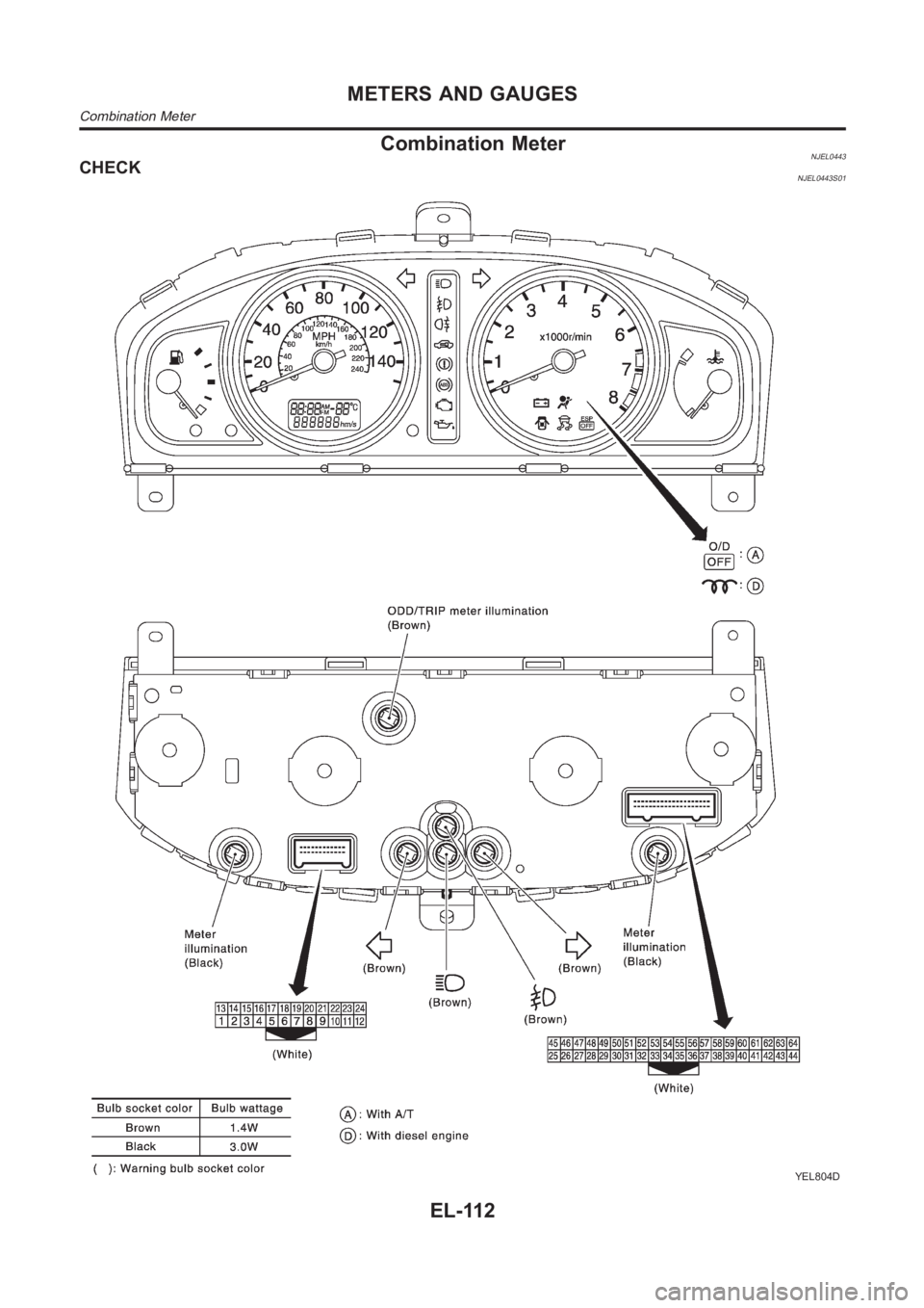
Combination MeterNJEL0443CHECKNJEL0443S01
YEL804D
METERS AND GAUGES
Combination Meter
EL-112
Page 2449 of 3189
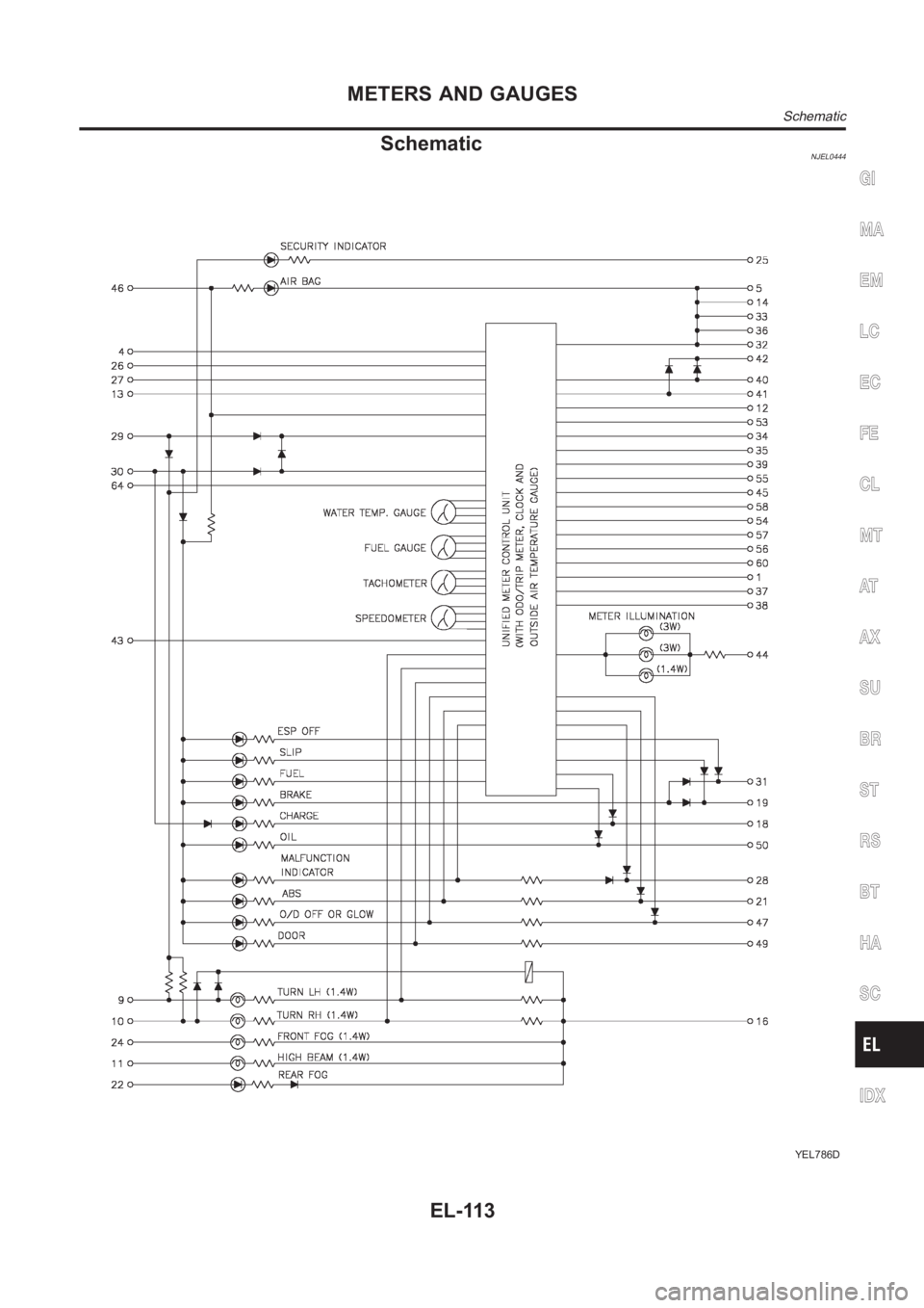
SchematicNJEL0444
YEL786D
GI
MA
EM
LC
EC
FE
CL
MT
AT
AX
SU
BR
ST
RS
BT
HA
SC
IDX
METERS AND GAUGES
Schematic
EL-113
Page 2450 of 3189
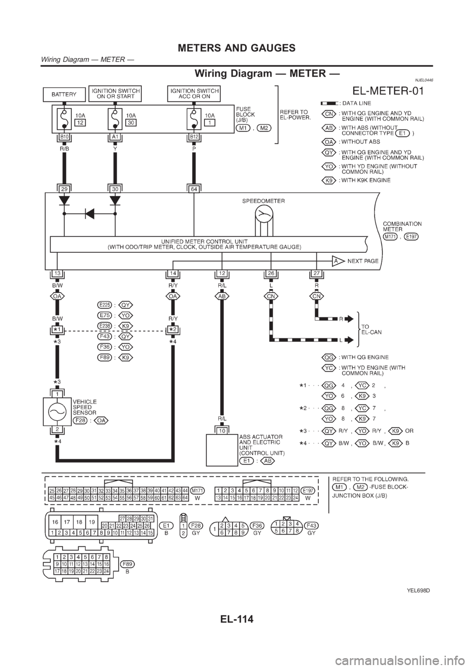
Wiring Diagram — METER —NJEL0446
YEL698D
METERS AND GAUGES
Wiring Diagram — METER —
EL-114
Trending: suspension, ec-72, Knock sensor, oil capacity, EC-132, interior room lamp, satellite navigation display
