NISSAN ALMERA N16 2003 Electronic Repair Manual
ALMERA N16 2003
NISSAN
NISSAN
https://www.carmanualsonline.info/img/5/57350/w960_57350-0.png
NISSAN ALMERA N16 2003 Electronic Repair Manual
Trending: neutral, clock reset, Diagnostic, remove seats, warning, ESP, turn signal
Page 2461 of 3189
INSPECTION/ENGINE REVOLUTION SIGNAL (YD
ENGINE MODELS WITHOUT COMMON RAIL)
=NJEL0448S05
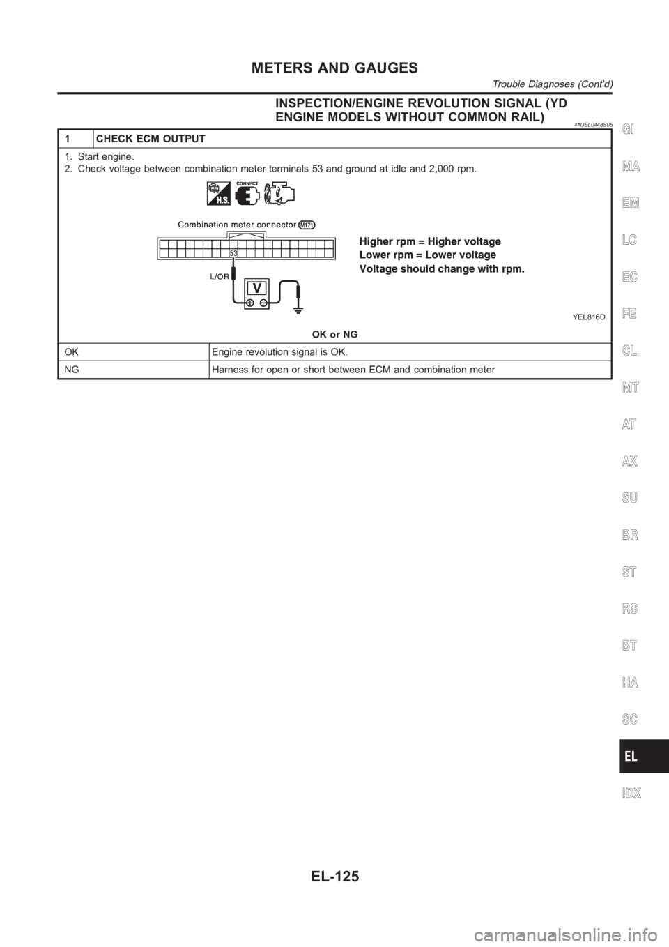
1 CHECK ECM OUTPUT
1. Start engine.
2. Check voltage between combination meter terminals 53 and ground at idleand 2,000 rpm.
YEL816D
OK or NG
OK Engine revolution signal is OK.
NG Harness for open or short between ECM and combination meter
GI
MA
EM
LC
EC
FE
CL
MT
AT
AX
SU
BR
ST
RS
BT
HA
SC
IDX
METERS AND GAUGES
Trouble Diagnoses (Cont’d)
EL-125
Page 2462 of 3189
INSPECTION/FUEL LEVEL SENSOR UNIT=NJEL0448S06
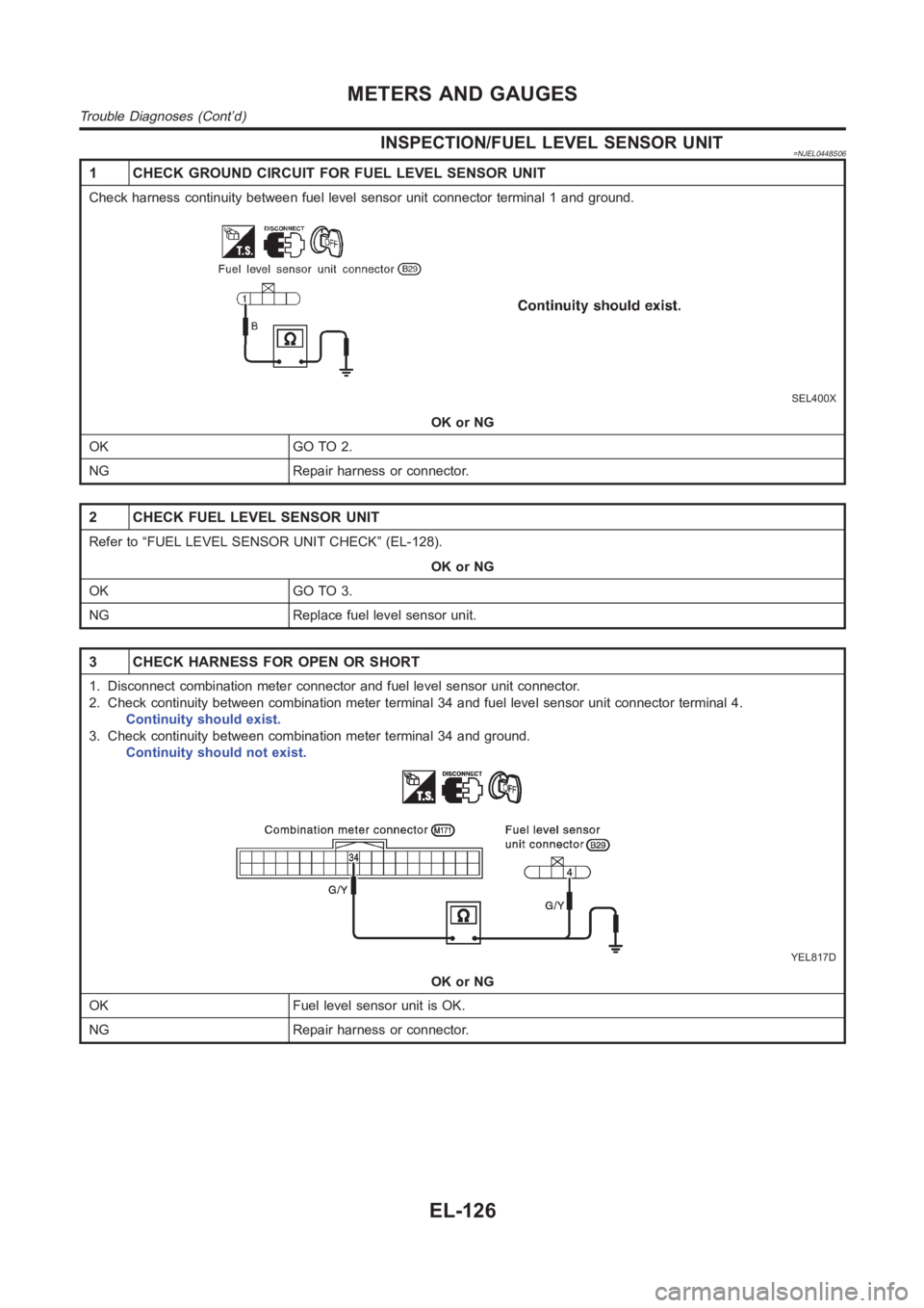
1 CHECK GROUND CIRCUIT FOR FUEL LEVEL SENSOR UNIT
Check harness continuity between fuel level sensor unit connector terminal 1 and ground.
SEL400X
OK or NG
OK GO TO 2.
NG Repair harness or connector.
2 CHECK FUEL LEVEL SENSOR UNIT
Refer to “FUEL LEVEL SENSOR UNIT CHECK” (EL-128).
OK or NG
OK GO TO 3.
NG Replace fuel level sensor unit.
3 CHECK HARNESS FOR OPEN OR SHORT
1. Disconnect combination meter connector and fuel level sensor unit connector.
2. Check continuity between combination meter terminal 34 and fuel level sensor unit connector terminal 4.
Continuity should exist.
3. Check continuity between combination meter terminal 34 and ground.
Continuity should not exist.
YEL817D
OK or NG
OK Fuel level sensor unit is OK.
NG Repair harness or connector.
METERS AND GAUGES
Trouble Diagnoses (Cont’d)
EL-126
Page 2463 of 3189
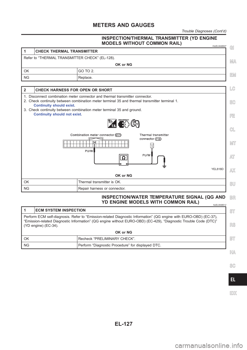
INSPECTION/THERMAL TRANSMITTER (YD ENGINE
MODELS WITHOUT COMMON RAIL)
=NJEL0448S07
1 CHECK THERMAL TRANSMITTER
Refer to “THERMAL TRANSMITTER CHECK” (EL-128).
OK or NG
OK GO TO 2.
NG Replace.
2 CHECK HARNESS FOR OPEN OR SHORT
1. Disconnect combination meter connector and thermal transmitter connector.
2. Check continuity between combination meter terminal 35 and thermal transmitter terminal 1.
Continuity should exist.
3. Check continuity between combination meter terminal 35 and ground.
Continuity should not exist.
YEL818D
OK or NG
OK Thermal transmitter is OK.
NG Repair harness or connector.
INSPECTION/WATER TEMPERATURE SIGNAL (QG AND
YD ENGINE MODELS WITH COMMON RAIL)
NJEL0448S12
1 ECM SYSTEM INSPECTION
Perform ECM self-diagnosis. Refer to “Emission-related Diagnostic Information” (QG engine with EURO-OBD) (EC-37),
“Emission-related Diagnostic Information” (QG engine without EURO-OBD) (EC-429), “Diagnostic Trouble Code (DTC)”
(YD engine) (EC-34).
OK or NG
OK Recheck “PRELIMINARY CHECK”.
NG Perform “Diagnostic Procedure” for displayed DTC.
GI
MA
EM
LC
EC
FE
CL
MT
AT
AX
SU
BR
ST
RS
BT
HA
SC
IDX
METERS AND GAUGES
Trouble Diagnoses (Cont’d)
EL-127
Page 2464 of 3189
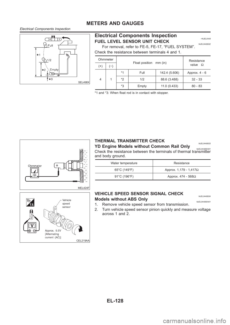
SEL498X
Electrical Components Inspection=NJEL0449FUEL LEVEL SENSOR UNIT CHECKNJEL0449S02For removal, refer to FE-5, FE-17, “FUEL SYSTEM”.
Check the resistance between terminals 4 and 1.
Ohmmeter
Float position mm (in)Resistance
valueΩ
(+) (−)
41*1 Full 142.4 (5.606) Approx. 4 - 6
*2 1/2 88.6 (3.488) 32 - 33
*3 Empty 11.0 (0.433) 80 - 83
*1 and *3: When float rod is in contact with stopper.
MEL424F
THERMAL TRANSMITTER CHECKNJEL0449S03YD Engine Models without Common Rail OnlyNJEL0449S0301Check the resistance between the terminals of thermal transmitter
and body ground.
Water temperature Resistance
65°C (149°F) Approx. 1,179 - 1,417Ω
91°C (196°F) Approx. 474 - 568Ω
CEL219AA
VEHICLE SPEED SENSOR SIGNAL CHECKNJEL0449S04Models without ABS OnlyNJEL0449S04011. Remove vehicle speed sensor from transmission.
2. Turn vehicle speed sensor pinion quickly and measure voltage
across 1 and 2.
METERS AND GAUGES
Electrical Components Inspection
EL-128
Page 2465 of 3189
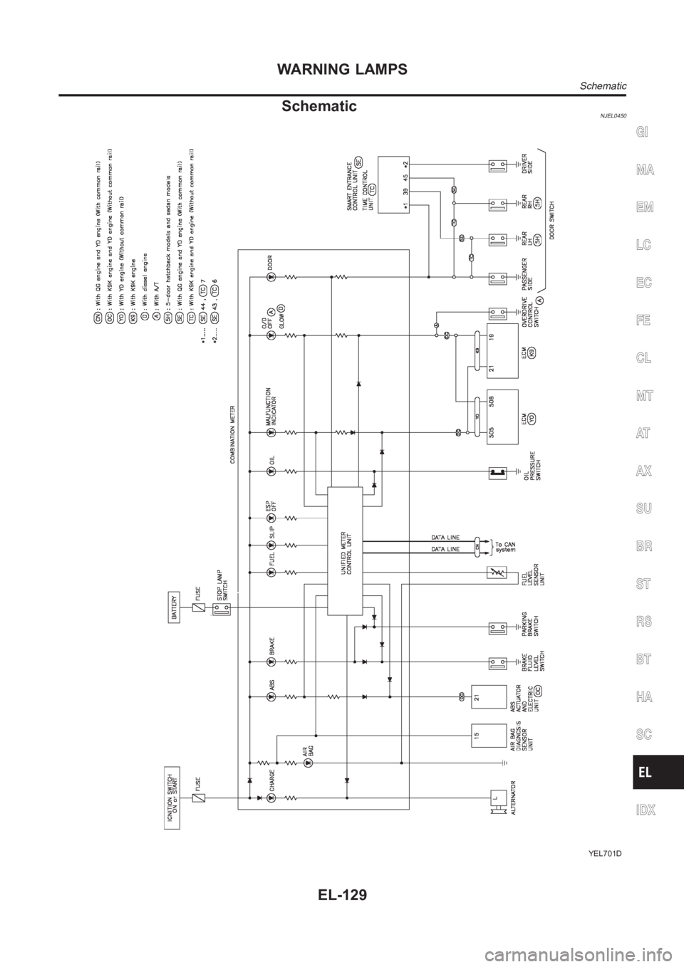
SchematicNJEL0450
YEL701D
GI
MA
EM
LC
EC
FE
CL
MT
AT
AX
SU
BR
ST
RS
BT
HA
SC
IDX
WARNING LAMPS
Schematic
EL-129
Page 2466 of 3189
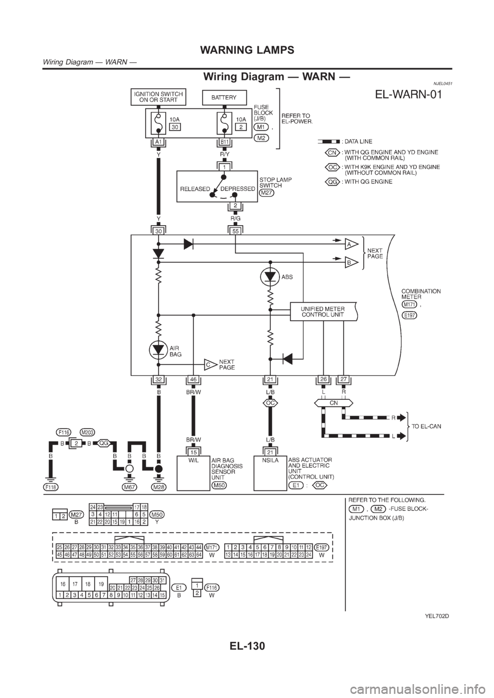
Wiring Diagram — WARN —NJEL0451
YEL702D
WARNING LAMPS
Wiring Diagram — WARN —
EL-130
Page 2467 of 3189
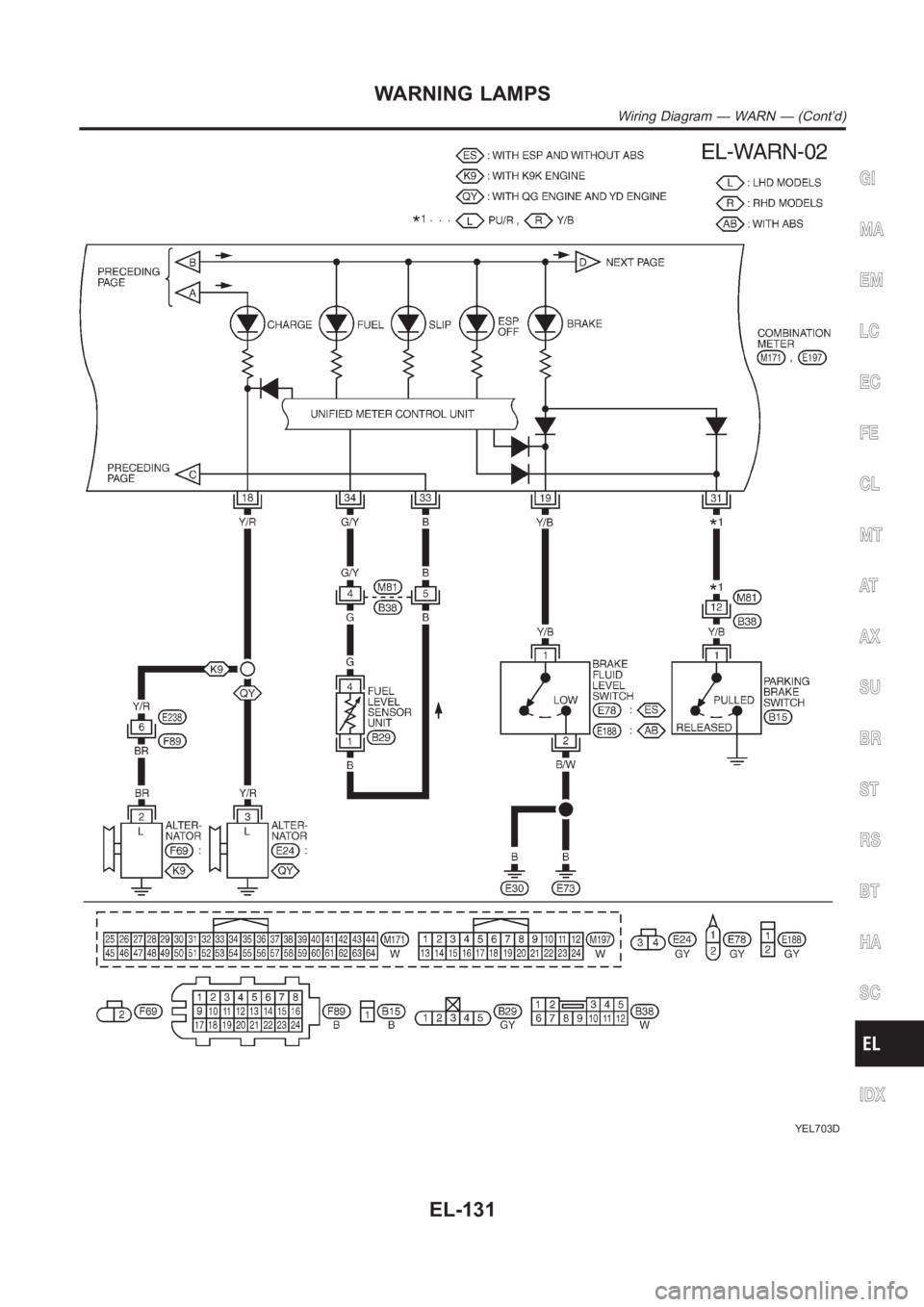
YEL703D
GI
MA
EM
LC
EC
FE
CL
MT
AT
AX
SU
BR
ST
RS
BT
HA
SC
IDX
WARNING LAMPS
Wiring Diagram — WARN — (Cont’d)
EL-131
Page 2468 of 3189
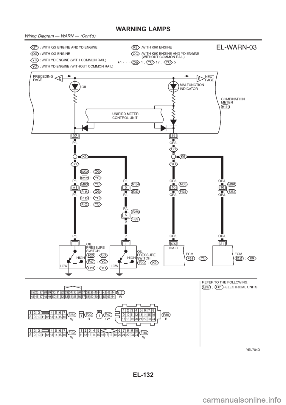
YEL704D
WARNING LAMPS
Wiring Diagram — WARN — (Cont’d)
EL-132
Page 2469 of 3189
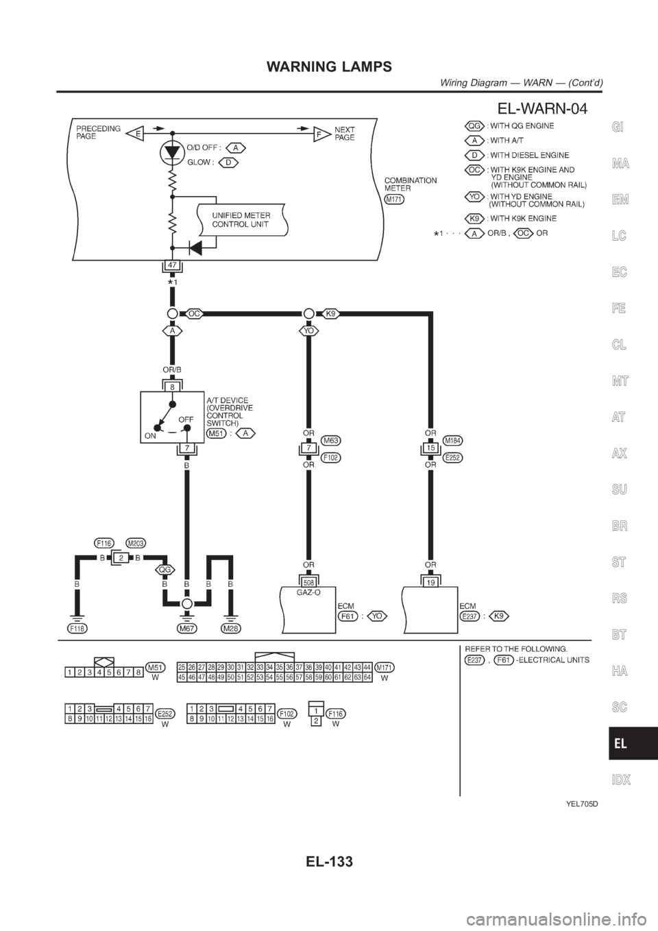
YEL705D
GI
MA
EM
LC
EC
FE
CL
MT
AT
AX
SU
BR
ST
RS
BT
HA
SC
IDX
WARNING LAMPS
Wiring Diagram — WARN — (Cont’d)
EL-133
Page 2470 of 3189
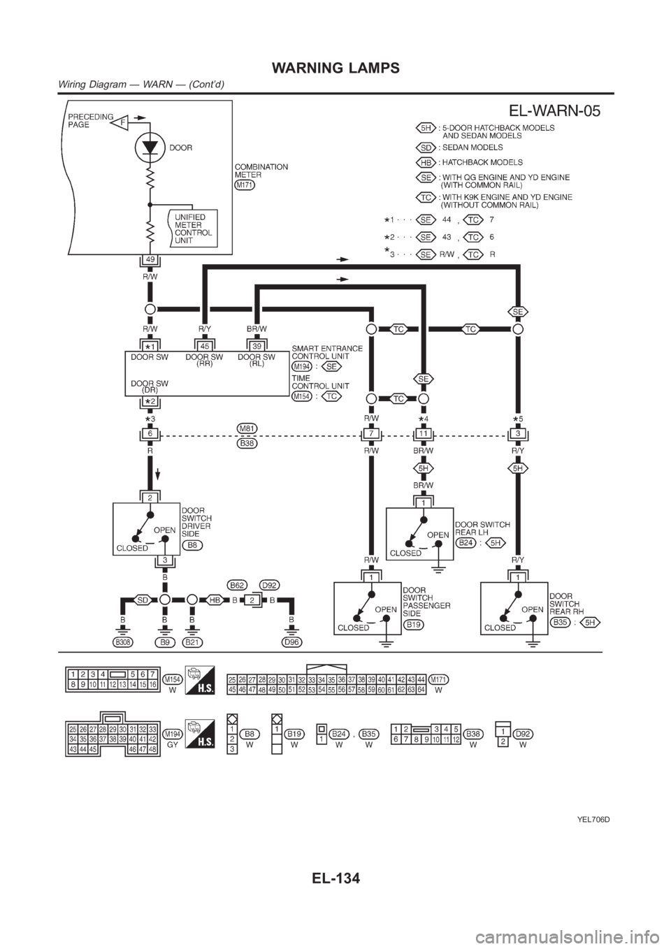
YEL706D
WARNING LAMPS
Wiring Diagram — WARN — (Cont’d)
EL-134
Trending: radio wire, Minute, p1251, Fuse box diagram, SRS connector, spark plugs replace, jacking
