NISSAN ALMERA N16 2003 Electronic Repair Manual
Manufacturer: NISSAN, Model Year: 2003, Model line: ALMERA N16, Model: NISSAN ALMERA N16 2003Pages: 3189, PDF Size: 54.76 MB
Page 2471 of 3189
NEL796
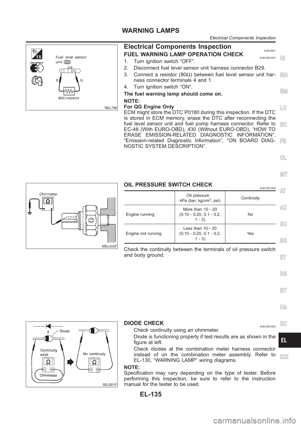
Electrical Components InspectionNJEL0051FUEL WARNING LAMP OPERATION CHECKNJEL0051S011. Turn ignition switch “OFF”.
2. Disconnect fuel level sensor unit harness connector B29.
3. Connect a resistor (80Ω) between fuel level sensor unit har-
ness connector terminals 4 and 1.
4. Turn ignition switch “ON”.
The fuel warning lamp should come on.
NOTE:
For QG Engine Only
ECM might store the DTC P0180 during this inspection. If the DTC
is stored in ECM memory, erase the DTC after reconnecting the
fuel level sensor unit and fuel pump harness connector. Refer to
EC-48 (With EURO-OBD), 430 (Without EURO-OBD), “HOW TO
ERASE EMISSION-RELATED DIAGNOSTIC INFORMATION”,
“Emission-related Diagnostic Information”, “ON BOARD DIAG-
NOSTIC SYSTEM DESCRIPTION”.
MEL425F
OIL PRESSURE SWITCH CHECKNJEL0051S02
Oil pressure
kPa (bar, kg/cm2, psi)Continuity
Engine runningMore than 10 - 20
(0.10 - 0.20, 0.1 - 0.2,
1-3)No
Engine not runningLess than 10 - 20
(0.10 - 0.20, 0.1 - 0.2,
1-3)Ye s
Check the continuity between the terminals of oil pressure switch
and body ground.
SEL901F
DIODE CHECKNJEL0051S03Check continuity using an ohmmeter.
Diode is functioning properly if test results are as shown in the
figure at left.
Check diodes at the combination meter harness connector
instead of on the combination meter assembly. Refer to
EL-130, “WARNING LAMP” wiring diagrams.
NOTE:
Specification may vary depending on the type of tester. Before
performing this inspection, be sure to refer to the instruction
manual for the tester to be used.
GI
MA
EM
LC
EC
FE
CL
MT
AT
AX
SU
BR
ST
RS
BT
HA
SC
IDX
WARNING LAMPS
Electrical Components Inspection
EL-135
Page 2472 of 3189
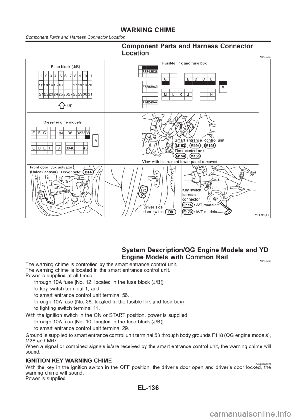
Component Parts and Harness Connector
Location
NJEL0452
YEL819D
System Description/QG Engine Models and YD
Engine Models with Common Rail
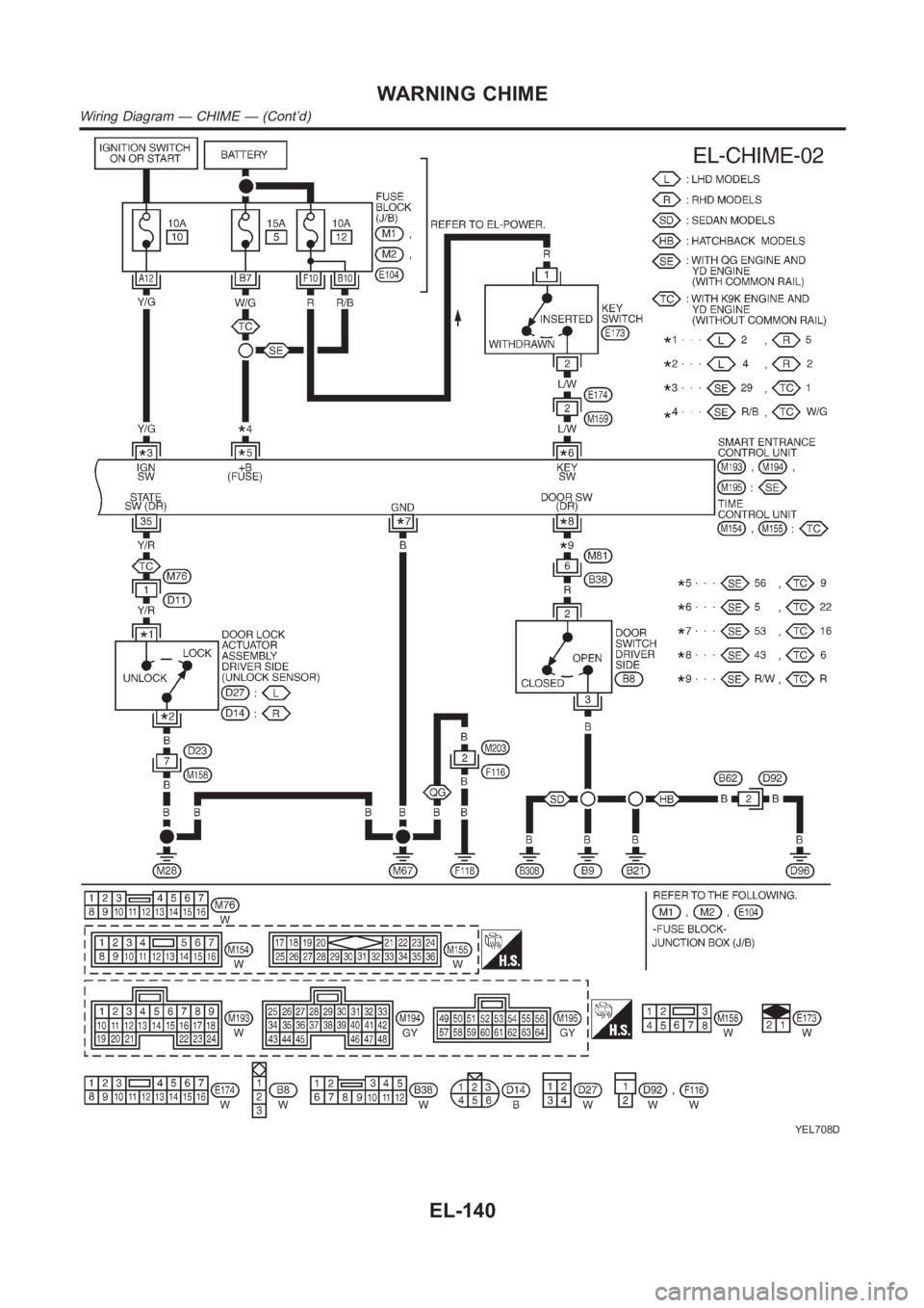
NJEL0453The warning chime is controlled by the smart entrance control unit.
The warning chime is located in the smart entrance control unit.
Power is supplied at all times
through 10A fuse [No. 12, located in the fuse block (J/B)]
to key switch terminal 1, and
to smart entrance control unit terminal 56.
through 10A fuse (No. 38, located in the fusible link and fuse box)
to lighting switch terminal 11.
With the ignition switch in the ON or START position, power is supplied
through 10A fuse [No. 10, located in the fuse block (J/B)]
to smart entrance control unit terminal 29.
Ground is supplied to smart entrance control unit terminal 53 through bodygrounds F118 (QG engine models),
M28 and M67.
When a signal or combined signals is/are received by the smart entrance control unit, the warning chime will
sound.
IGNITION KEY WARNING CHIMENJEL0453S01With the key in the ignition switch in the OFF position, the driver’s door open and driver’s door locked, the
warning chime will sound.
Power is supplied
WARNING CHIME
Component Parts and Harness Connector Location
EL-136
Page 2473 of 3189
from key switch terminal 2
to smart entrance control unit terminal 5.
Ground is supplied
from body grounds B9, B21 and D96 (Hatchback) or B308 (Sedan)
through front door switch (driver side) terminal 3 and 2
to smart entrance control unit terminal 43.
And, then smart entrance control unit receives any door lock signal.
LIGHT WARNING CHIMENJEL0453S02With ignition switch OFF, driver’s door open, and lighting switch in 1ST or2ND position, warning chime will
sound. Power is supplied.
from lighting switch terminal 12
through daytime light control unit terminals 11 and 10 (with daytime lightsystem)
to smart entrance control unit terminal 17
Ground is supplied
from front door switch (driver side) terminal 2
to smart entrance control unit terminal 43.
Front door switch (driver side) terminal 3 is grounded through body grounds B9, B21 and D96 (Hatchback) or
B308 (Sedan).
System Description/YD Engine Models without
Common Rail and K9K Engine Models
NJEL0550The warning chime is controlled by the time control unit.
The warning chime is located in the time control unit.
Power is supplied at all times
through 15A fuse [No. 5, located in fuse block (J/B)]
to time control unit terminal 9.
through 10A fuse [No. 12, located in the fuse block (J/B)]
to key switch terminal 1.
through 10A fuse (No. 38, located in the fuse and fusible link box)
to lighting switch terminal 11.
With the ignition switch in the ON or START position, power is supplied
through 10A fuse [No. 10, located in the fuse block (J/B)]
to time control unit terminal 1.
Ground is supplied to time control unit terminal 16 through body grounds M28 and M67.
When a signal, or combination of signals, is received by the time control unit, the warning chime will sound.
IGNITION KEY WARNING CHIMENJEL0550S01With the key in the ignition switch in the OFF position, the driver’s door open and driver’s door locked, the
warning chime will sound. Power is supplied
from key switch terminal 2
to time control unit terminal 22.
Ground is supplied
from body grounds B9, B21 and D96 (Hatchback) or B308 (Sedan)
through front door switch (driver side) terminal 3 and 2
to time control unit terminal 6, and
Ground is interrupted,
from body grounds M28 and M67
to time control unit terminal 35
LIGHT WARNING CHIMENJEL0550S02With ignition switch OFF, driver’s door open, and lighting switch in 1ST or2ND position, warning chime will
sound. Power is supplied.
from lighting switch terminal 12
to time control unit terminal 10
GI
MA
EM
LC
EC
FE
CL
MT
AT
AX
SU
BR
ST
RS
BT
HA
SC
IDX
WARNING CHIME
System Description/QG Engine Models and YD Engine Models with Common Rail(Cont’d)
EL-137
Page 2474 of 3189

Ground is supplied
from front door switch (driver side) terminal 2
to time control unit terminal 6.
Front door switch (driver side) terminal 3 is grounded through body grounds B9, B21 and D96 (Hatchback) or
B308 (Sedan).
WARNING CHIME
System Description/YD Engine Models without Common Rail and K9K Engine Models (Cont’d)
EL-138
Page 2475 of 3189
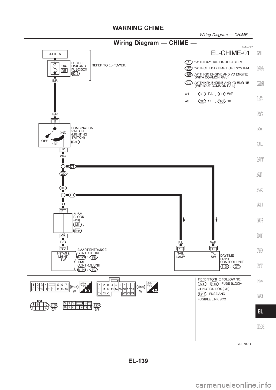
Wiring Diagram — CHIME —NJEL0454
YEL707D
GI
MA
EM
LC
EC
FE
CL
MT
AT
AX
SU
BR
ST
RS
BT
HA
SC
IDX
WARNING CHIME
Wiring Diagram — CHIME —
EL-139
Page 2476 of 3189
YEL708D
WARNING CHIME
Wiring Diagram — CHIME — (Cont’d)
EL-140
Page 2477 of 3189
Trouble Diagnoses/QG and YD Engine Models
with Common Rail
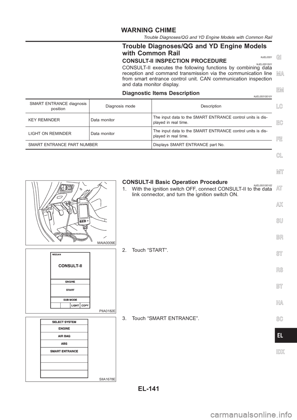
NJEL0551CONSULT-II INSPECTION PROCEDURENJEL0551S01CONSULT-II executes the following functions by combining data
reception and command transmission via the communication line
from smart entrance control unit. CAN communication inspection
and data monitor display.
Diagnostic Items DescriptionNJEL0551S0101
SMART ENTRANCE diagnosis
positionDiagnosis mode Description
KEY REMINDER Data monitorThe input data to the SMART ENTRANCE control units is dis-
played in real time.
LIGHT ON REMINDER Data monitorThe input data to the SMART ENTRANCE control units is dis-
played in real time.
SMART ENTRANCE PART NUMBER Displays SMART ENTRANCE part No.
MAIA0009E
CONSULT-II Basic Operation ProcedureNJEL0551S01021. With the ignition switch OFF, connect CONSULT-II to the data
link connector, and turn the ignition switch ON.
PIIA0182E
2. Touch “START”.
SIIA1678E
3. Touch “SMART ENTRANCE”.
GI
MA
EM
LC
EC
FE
CL
MT
AT
AX
SU
BR
ST
RS
BT
HA
SC
IDX
WARNING CHIME
Trouble Diagnoses/QG and YD Engine Models with Common Rail
EL-141
Page 2478 of 3189
![NISSAN ALMERA N16 2003 Electronic Repair Manual 4. Select the desired part to be diagnosed on the “SELECT TES-
T ITEM” screen.
Data monitor item (KEY REMINDER)
Monitored item Description
IGNITION SW Indicates [ON/OFF] condition of ignition swit NISSAN ALMERA N16 2003 Electronic Repair Manual 4. Select the desired part to be diagnosed on the “SELECT TES-
T ITEM” screen.
Data monitor item (KEY REMINDER)
Monitored item Description
IGNITION SW Indicates [ON/OFF] condition of ignition swit](/img/5/57350/w960_57350-2477.png)
4. Select the desired part to be diagnosed on the “SELECT TES-
T ITEM” screen.
Data monitor item (KEY REMINDER)
Monitored item Description
IGNITION SW Indicates [ON/OFF] condition of ignition switch.
KEY IN DETECT Indicates [ON/OFF] condition of electronic key switch.
DR DOOR SW Indicates [ON/OFF] condition of front door switch (driver side).
CDL LOCK SW Indicates [ON/OFF] condition of door lock/unlock switch.
RKE LOCK Indicates [ON/OFF] condition of lock signal from remote controller.
Data monitor item (Light warning chime)
Monitored item Description
IGN ON SW Indicates [ON/OFF] condition of ignition switch.
DR DOOR SW Indicates [ON/OFF] condition of front door switch (driver side).
TAIL LAMP ON Indicates [ON/OFF] condition of lighting switch.
SYMPTOM CHARTNJEL0551S02First perform the “SELF-DIAG RESULTS” in “SMART ENTRANCE”
with CONSULT-II, when perform the each trouble diagnosis.
Symptom Diagnoses/Service procedure Reference page
Light warning chime does not activate.Power supply and ground circuit checkEL-143, “Power Supply
and Ground Circuit
Check”
Lighting switch checkEL-144, “Lighting Switch
Input Signal Check”
Front door switch (driver side) checkEL-150, “Front Door
Switch (Driver side)
Check”
Key warning chime does not activate.Power supply and ground circuit checkEL-143, “Power Supply
and Ground Circuit
Check”
Key switch insert signal checkEL-147, “Key Switch
Insert Signal Check”
Front door switch (driver side) checkEL-150, “Front Door
Switch (Driver side)
Check”
All warning chimes do not activate. Power supply and ground circuit checkEL-143, “Power Supply
and Ground Circuit
Check”
With the ignition switch turned OFF and the
door closed (driver side) turning the lighting
switch ON (1st) activates the chime.Front door switch (driver side) checkEL-150, “Front Door
Switch (Driver side)
Check”
WARNING CHIME
Trouble Diagnoses/QG and YD Engine Models with Common Rail (Cont’d)
EL-142
Page 2479 of 3189
POWER SUPPLY AND GROUND CIRCUIT CHECKNJEL0551S03
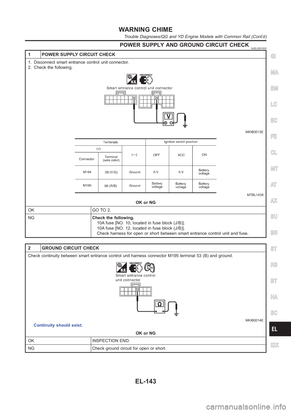
1 POWER SUPPLY CIRCUIT CHECK
1. Disconnect smart entrance control unit connector.
2. Check the following.
MKIB0013E
MTBL1438
OK or NG
OK GO TO 2.
NGCheck the following.
10A fuse [NO. 10, located in fuse block (J/B)].
10A fuse [NO. 12, located in fuse block (J/B)].
Check harness for open or short between smart entrance control unit and fuse.
2 GROUND CIRCUIT CHECK
Check continuity between smart entrance control unit harness connector M195 terminal 53 (B) and ground.
MKIB0014E
Continuity should exist.
OK or NG
OK INSPECTION END.
NG Check ground circuit for open or short.
GI
MA
EM
LC
EC
FE
CL
MT
AT
AX
SU
BR
ST
RS
BT
HA
SC
IDX
WARNING CHIME
Trouble Diagnoses/QG and YD Engine Models with Common Rail (Cont’d)
EL-143
Page 2480 of 3189
LIGHTING SWITCH INPUT SIGNAL CHECK=NJEL0551S04
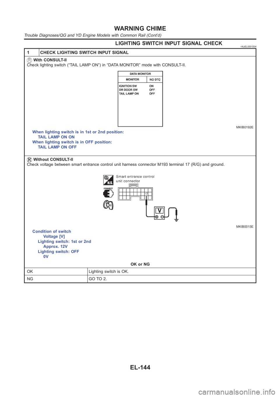
1 CHECK LIGHTING SWITCH INPUT SIGNAL
With CONSULT-II
Check lighting switch (“TAIL LAMP ON”) in “DATA MONITOR” mode with CONSULT-II.
MKIB0192E
When lighting switch is in 1st or 2nd position:
TAIL LAMP ON ON
When lighting switch is in OFF position:
TAIL LAMP ON OFF
Without CONSULT-II
Check voltage between smart entrance control unit harness connector M193terminal17(R/G)andground.
MKIB0015E
Condition of switch
Voltage [V]
Lighting switch: 1st or 2nd
Approx. 12V
Lighting switch: OFF
0V
OK or NG
OK Lighting switch is OK.
NG GO TO 2.
WARNING CHIME
Trouble Diagnoses/QG and YD Engine Models with Common Rail (Cont’d)
EL-144