NISSAN ALMERA N16 2003 Electronic Repair Manual
ALMERA N16 2003
NISSAN
NISSAN
https://www.carmanualsonline.info/img/5/57350/w960_57350-0.png
NISSAN ALMERA N16 2003 Electronic Repair Manual
Trending: brakes, air conditioning, immobilizer, airbag off, engine overheat, starter relay, Engine control system
Page 3011 of 3189
Insufficient Heating
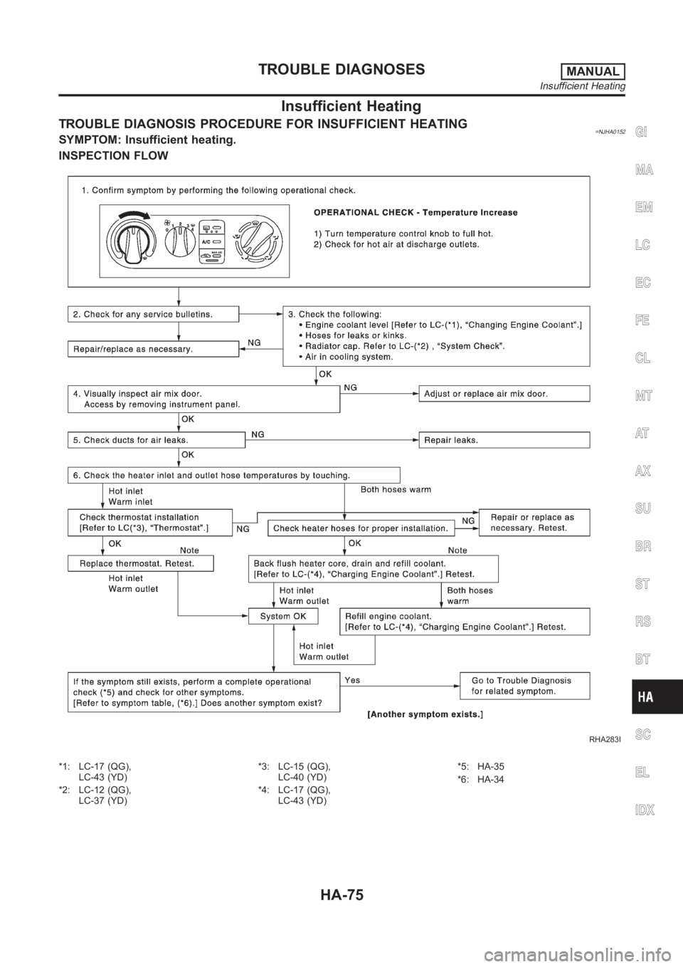
TROUBLE DIAGNOSIS PROCEDURE FOR INSUFFICIENT HEATING=NJHA0152SYMPTOM: Insufficient heating.
INSPECTION FLOW
RHA283I
*1: LC-17 (QG),
LC-43 (YD)
*2: LC-12 (QG),
LC-37 (YD)*3: LC-15 (QG),
LC-40 (YD)
*4: LC-17 (QG),
LC-43 (YD)*5: HA-35
*6: HA-34
GI
MA
EM
LC
EC
FE
CL
MT
AT
AX
SU
BR
ST
RS
BT
SC
EL
IDX
TROUBLE DIAGNOSESMANUAL
Insufficient Heating
HA-75
Page 3012 of 3189
Noise
TROUBLE DIAGNOSIS PROCEDURE FOR NOISE=NJHA0158SYMPTOM:
Noise
INSPECTION FLOW
RHA925H
*1: HA-84
*2: HA-85
*3: HA-79*4: EM-11 (QG),
EM-11 (YD)*5: LC-17 (QG),
LC-43 (YD)
TROUBLE DIAGNOSESMANUAL
Noise
HA-76
Page 3013 of 3189
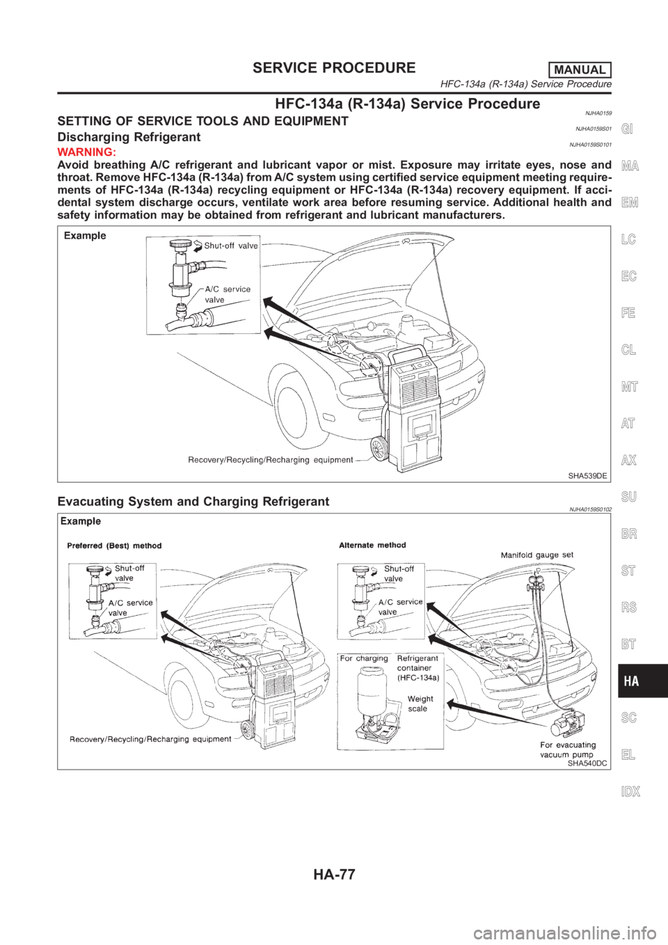
HFC-134a (R-134a) Service ProcedureNJHA0159SETTING OF SERVICE TOOLS AND EQUIPMENTNJHA0159S01Discharging RefrigerantNJHA0159S0101WARNING:
Avoid breathing A/C refrigerant and lubricant vapor or mist. Exposure mayirritate eyes, nose and
throat. Remove HFC-134a (R-134a) from A/C system using certified serviceequipment meeting require-
ments of HFC-134a (R-134a) recycling equipment or HFC-134a (R-134a) recovery equipment. If acci-
dental system discharge occurs, ventilate work area before resuming service. Additional health and
safety information may be obtained from refrigerant and lubricant manufacturers.
SHA539DE
Evacuating System and Charging RefrigerantNJHA0159S0102
SHA540DC
GI
MA
EM
LC
EC
FE
CL
MT
AT
AX
SU
BR
ST
RS
BT
SC
EL
IDX
SERVICE PROCEDUREMANUAL
HFC-134a (R-134a) Service Procedure
HA-77
Page 3014 of 3189
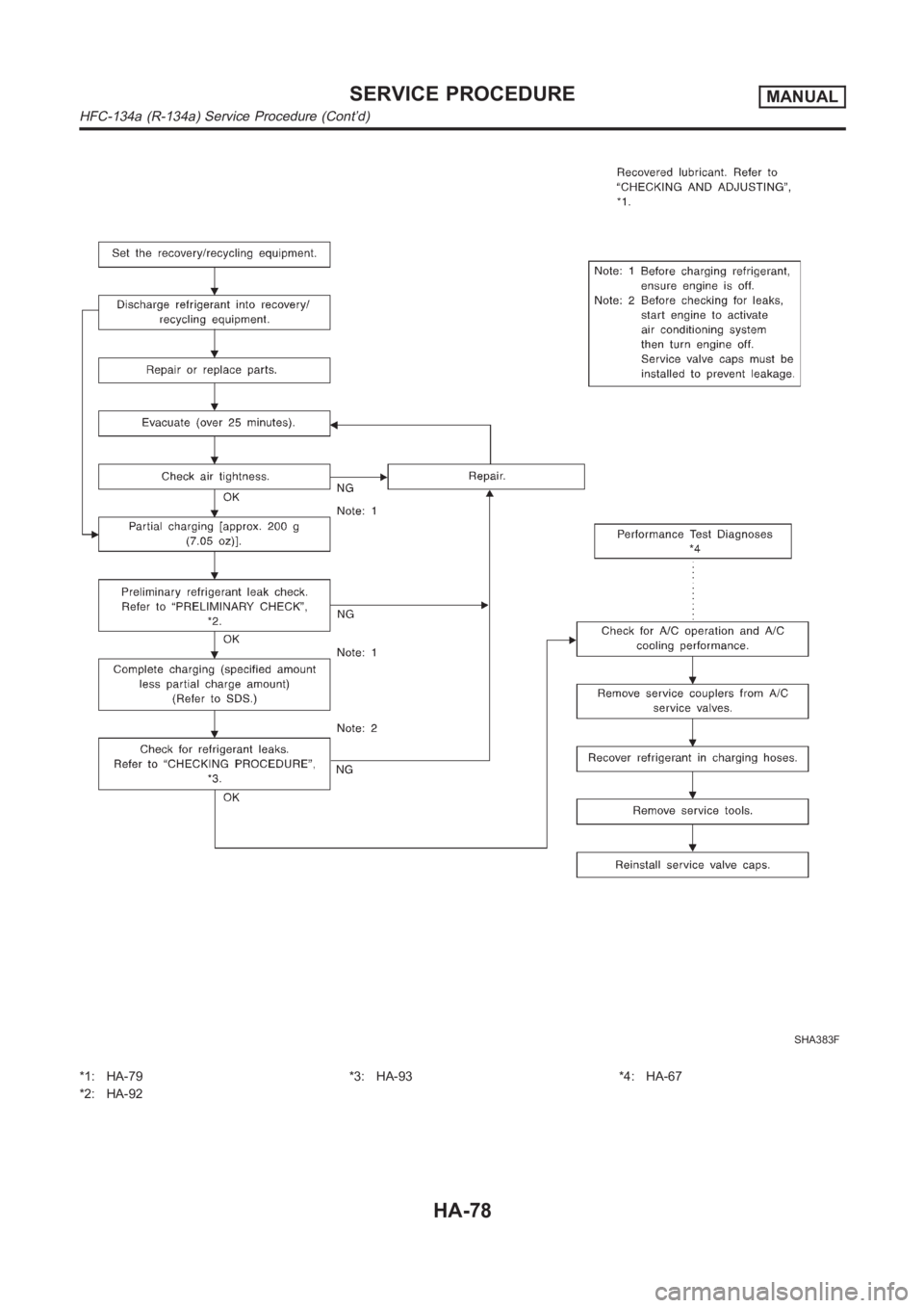
SHA383F
*1: HA-79
*2: HA-92*3: HA-93 *4: HA-67
SERVICE PROCEDUREMANUAL
HFC-134a (R-134a) Service Procedure (Cont’d)
HA-78
Page 3015 of 3189
Maintenance of Lubricant Quantity in
Compressor
NJHA0160The lubricant in the compressor circulates through the system with
the refrigerant. Add lubricant to compressor when replacing any
component or after a large gas leakage occurred. It is important to
maintain the specified amount.
If lubricant quantity is not maintained properly, the following mal-
functions may result:
Lack of lubricant: May lead to a seized compressor
Excessive lubricant: Inadequate cooling (thermal exchange
interference)
LUBRICANTNJHA0160S01Name: Nissan A/C System Oil Type S
Part number: KLH00-PAGS0
CHECKING AND ADJUSTINGNJHA0160S02Adjust the lubricant quantity according to the test group shown
below.
1 LUBRICANT RETURN OPERATION
Can lubricant return operation be performed?
A/C system works properly.
There is no evidence of a large amount of lubricant leakage.
YesorNo
Ye s G O T O 2 .
No GO TO 3.
2 PERFORM LUBRICANT RETURN OPERATION, PROCEEDING AS FOLLOWS
1. Start engine, and set the following conditions:
Test condition
Engine speed: Idling to 1,200 rpm
A/C switch: ON
Blower speed: Max. position
Temp. control: Optional [Set so that intake air temperature is 25 to 30°C (77 to 86°F).]
2. Perform lubricant return operation for about 10 minutes.
3. Stop engine.
CAUTION:
If excessive lubricant leakage is noted, do not perform the lubricant return operation.
GO TO 3.
3 CHECK COMPRESSOR
Should the compressor be replaced?
YesorNo
Yes GO TO HA-81.
No GO TO 4.
GI
MA
EM
LC
EC
FE
CL
MT
AT
AX
SU
BR
ST
RS
BT
SC
EL
IDX
SERVICE PROCEDUREMANUAL
Maintenance of Lubricant Quantity in Compressor
HA-79
Page 3016 of 3189
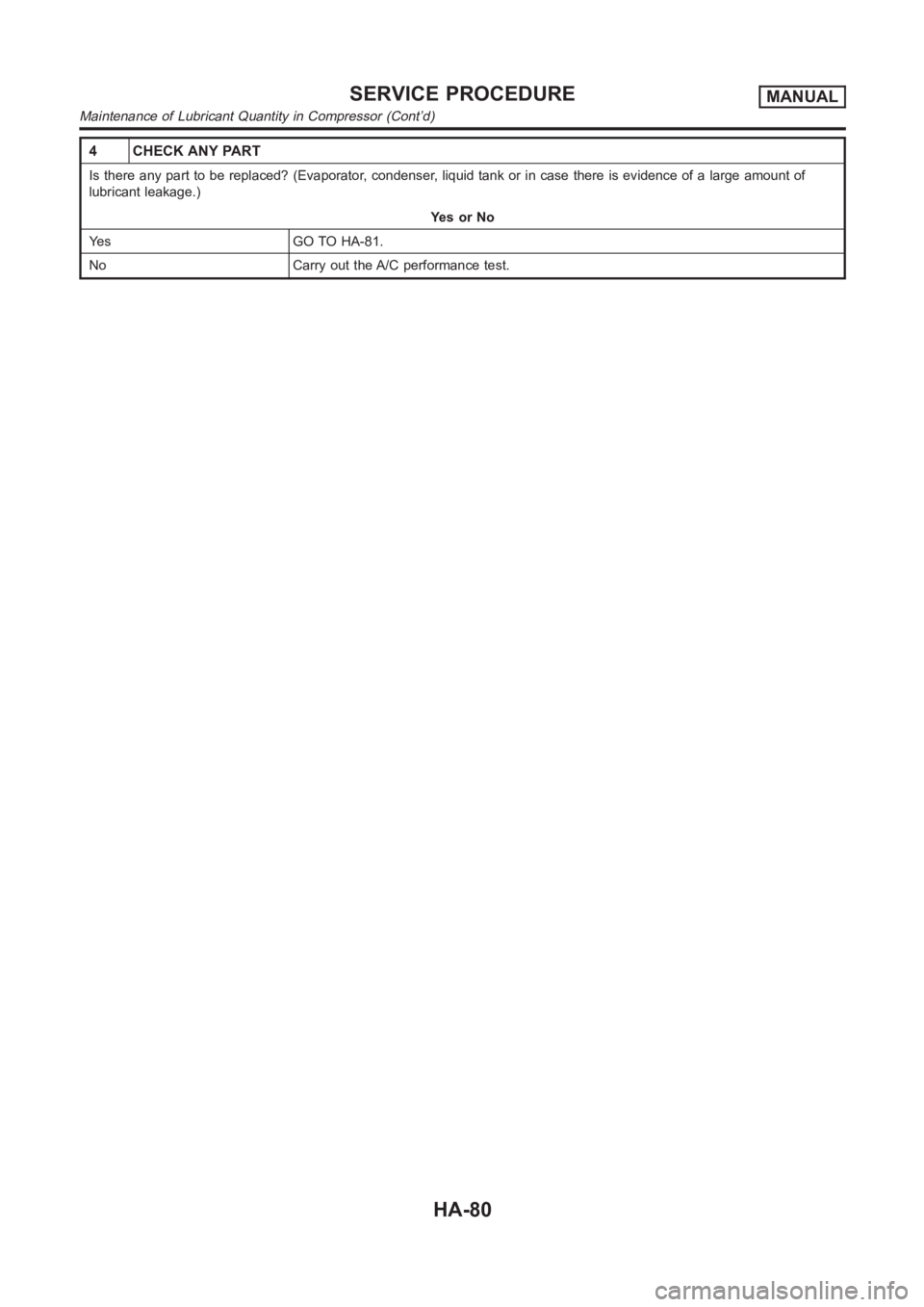
4 CHECK ANY PART
Is there any part to be replaced? (Evaporator, condenser, liquid tank or incase there is evidence of a large amount of
lubricant leakage.)
YesorNo
Yes GO TO HA-81.
No Carry out the A/C performance test.
SERVICE PROCEDUREMANUAL
Maintenance of Lubricant Quantity in Compressor (Cont’d)
HA-80
Page 3017 of 3189
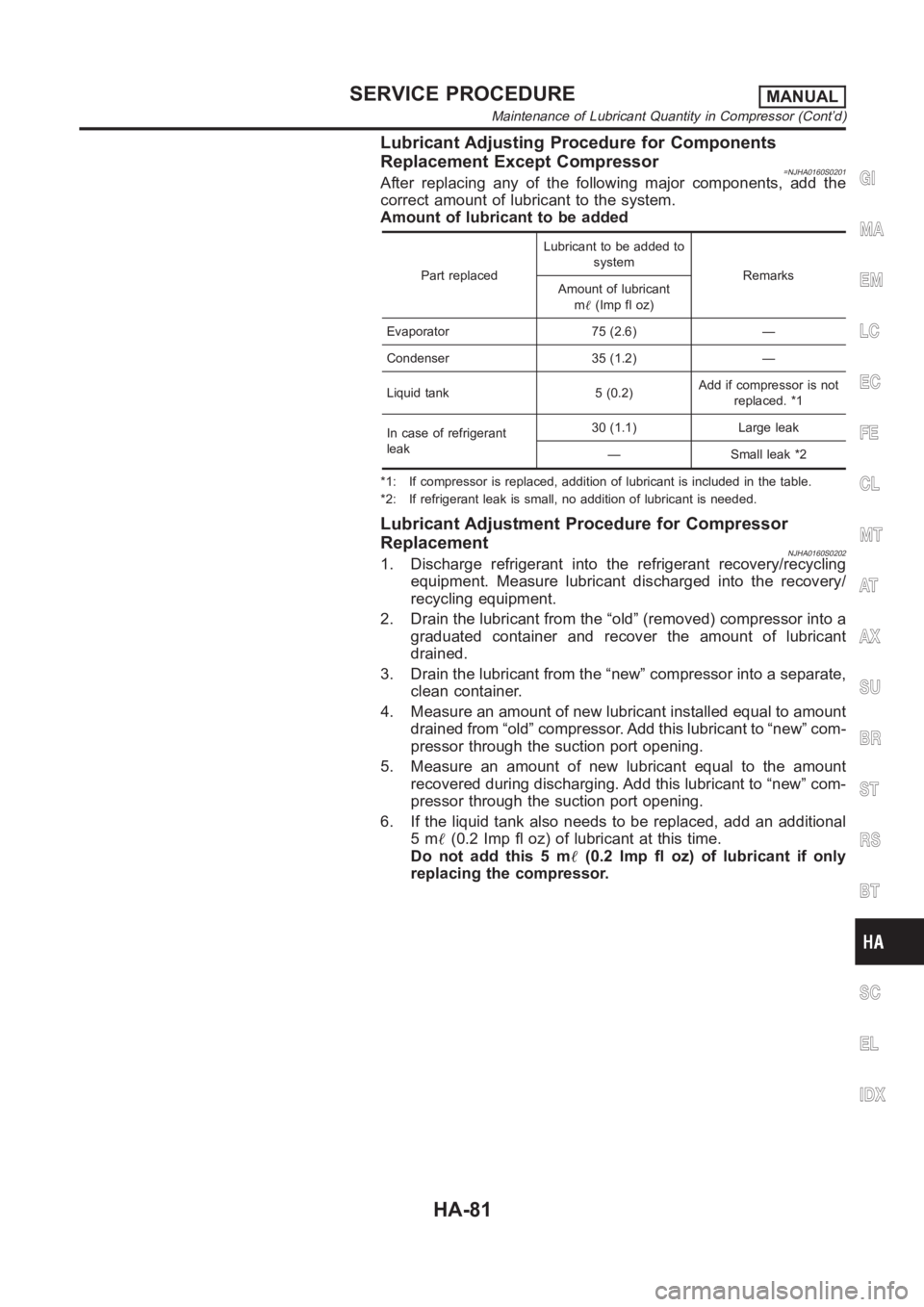
Lubricant Adjusting Procedure for Components
Replacement Except Compressor
=NJHA0160S0201After replacing any of the following major components, add the
correct amount of lubricant to the system.
Amount of lubricant to be added
Part replacedLubricant to be added to
system
Remarks
Amount of lubricant
m�(Imp fl oz)
Evaporator 75 (2.6) —
Condenser 35 (1.2) —
Liquid tank 5 (0.2)Add if compressor is not
replaced. *1
In case of refrigerant
leak30 (1.1) Large leak
— Small leak *2
*1: If compressor is replaced, addition of lubricant is included in the table.
*2: If refrigerant leak is small, no addition of lubricant is needed.
Lubricant Adjustment Procedure for Compressor
Replacement
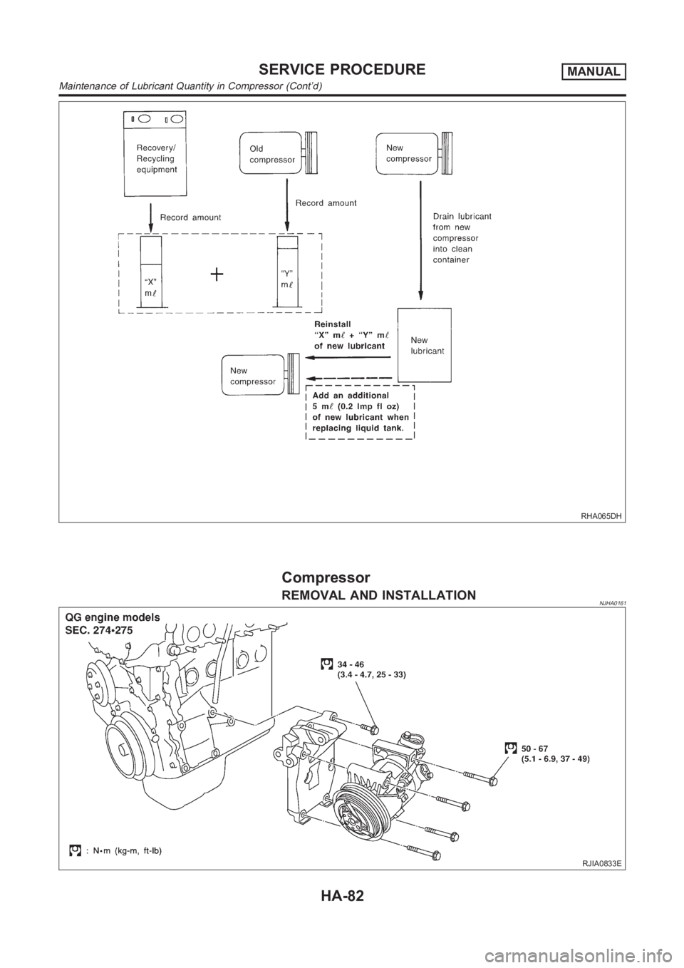
NJHA0160S02021. Discharge refrigerant into the refrigerant recovery/recycling
equipment. Measure lubricant discharged into the recovery/
recycling equipment.
2. Drain the lubricant from the “old” (removed) compressor into a
graduated container and recover the amount of lubricant
drained.
3. Drain the lubricant from the “new” compressor into a separate,
clean container.
4. Measure an amount of new lubricant installed equal to amount
drained from “old” compressor. Add this lubricant to “new” com-
pressor through the suction port opening.
5. Measure an amount of new lubricant equal to the amount
recovered during discharging. Add this lubricant to “new” com-
pressor through the suction port opening.
6. If the liquid tank also needs to be replaced, add an additional
5m�(0.2 Imp fl oz) of lubricant at this time.
Do not add this 5 m�(0.2 Imp fl oz) of lubricant if only
replacing the compressor.
GI
MA
EM
LC
EC
FE
CL
MT
AT
AX
SU
BR
ST
RS
BT
SC
EL
IDX
SERVICE PROCEDUREMANUAL
Maintenance of Lubricant Quantity in Compressor (Cont’d)
HA-81
Page 3018 of 3189
RHA065DH
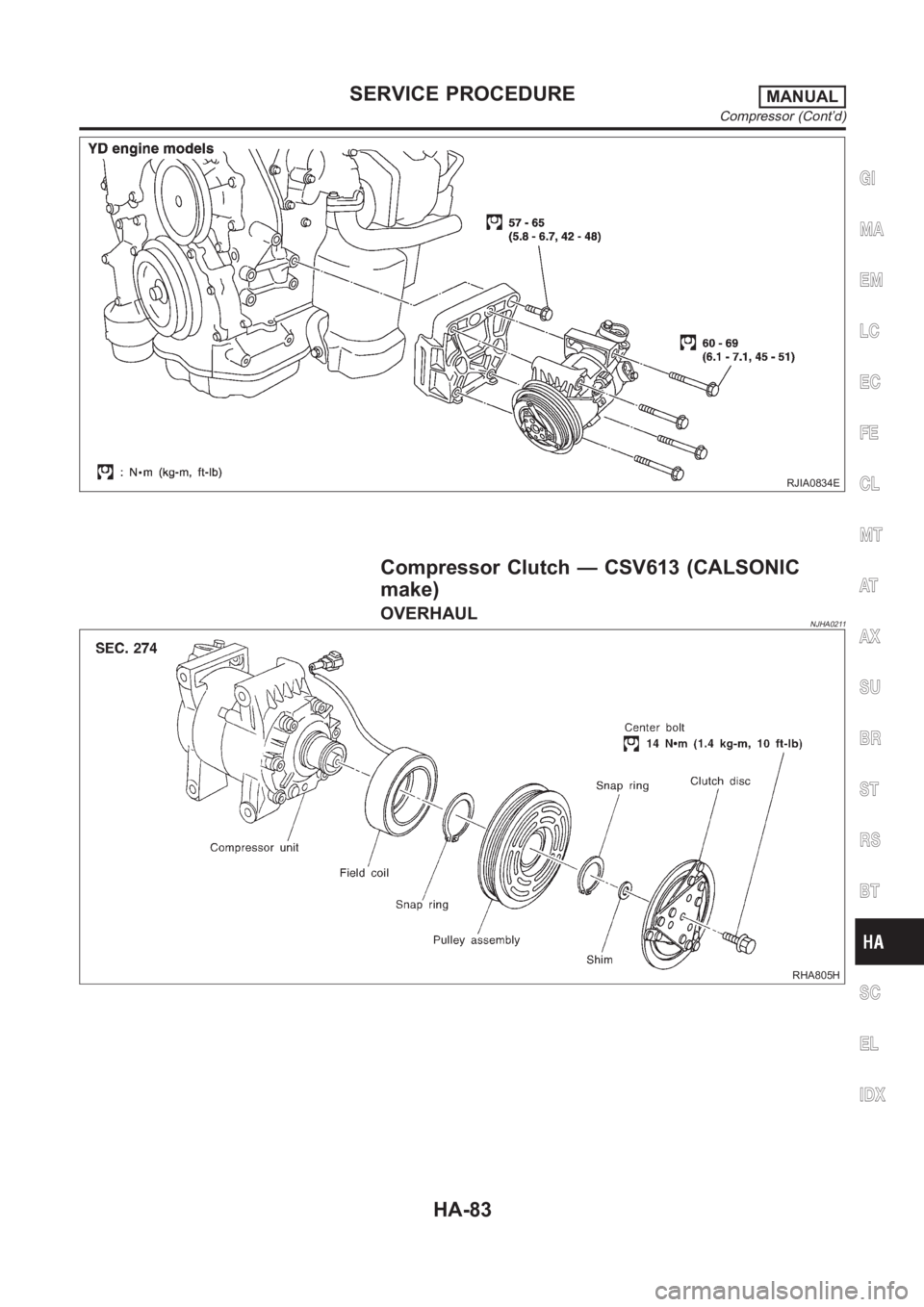
Compressor
REMOVAL AND INSTALLATIONNJHA0161
RJIA0833E
SERVICE PROCEDUREMANUAL
Maintenance of Lubricant Quantity in Compressor (Cont’d)
HA-82
Page 3019 of 3189
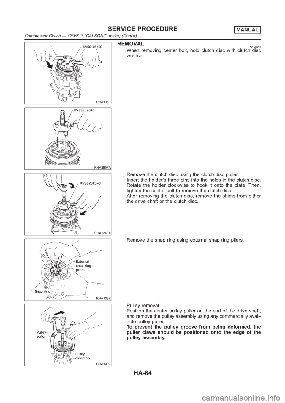
RJIA0834E
Compressor Clutch — CSV613 (CALSONIC
make)
OVERHAULNJHA0211
RHA805H
GI
MA
EM
LC
EC
FE
CL
MT
AT
AX
SU
BR
ST
RS
BT
SC
EL
IDX
SERVICE PROCEDUREMANUAL
Compressor (Cont’d)
HA-83
Page 3020 of 3189
RHA136E
REMOVALNJHA0212When removing center bolt, hold clutch disc with clutch disc
wrench.
RHA399FA
RHA124FA
Remove the clutch disc using the clutch disc puller.
Insert the holder’s three pins into the holes in the clutch disc.
Rotate the holder clockwise to hook it onto the plate. Then,
tighten the center bolt to remove the clutch disc.
After removing the clutch disc, remove the shims from either
the drive shaft or the clutch disc.
RHA138E
Remove the snap ring using external snap ring pliers.
RHA139E
Pulley removal
Position the center pulley puller on the end of the drive shaft,
and remove the pulley assembly using any commercially avail-
able pulley puller.
To prevent the pulley groove from being deformed, the
puller claws should be positioned onto the edge of the
pulley assembly.
SERVICE PROCEDUREMANUAL
Compressor Clutch — CSV613 (CALSONIC make) (Cont’d)
HA-84
Trending: tire pressure, alternator, warning light, navigation update, bulbs, PHASE, radio antenna
