NISSAN ALMERA N16 2003 Electronic Repair Manual
ALMERA N16 2003
NISSAN
NISSAN
https://www.carmanualsonline.info/img/5/57350/w960_57350-0.png
NISSAN ALMERA N16 2003 Electronic Repair Manual
Trending: battery, four wheel drive, engine oil, fuel tank removal, ball joint, charging, clock setting
Page 2981 of 3189
Blower Motor
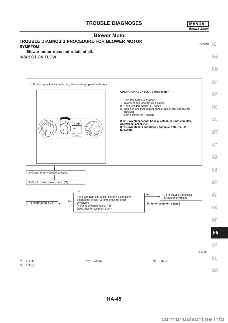
TROUBLE DIAGNOSIS PROCEDURE FOR BLOWER MOTOR=NJHA0145SYMPTOM:
Blower motor does not rotate at all.
INSPECTION FLOW
NHA385
*1: HA-46
*2: HA-35*3: HA-34 *4: HA-35
GI
MA
EM
LC
EC
FE
CL
MT
AT
AX
SU
BR
ST
RS
BT
SC
EL
IDX
TROUBLE DIAGNOSESMANUAL
Blower Motor
HA-45
Page 2982 of 3189
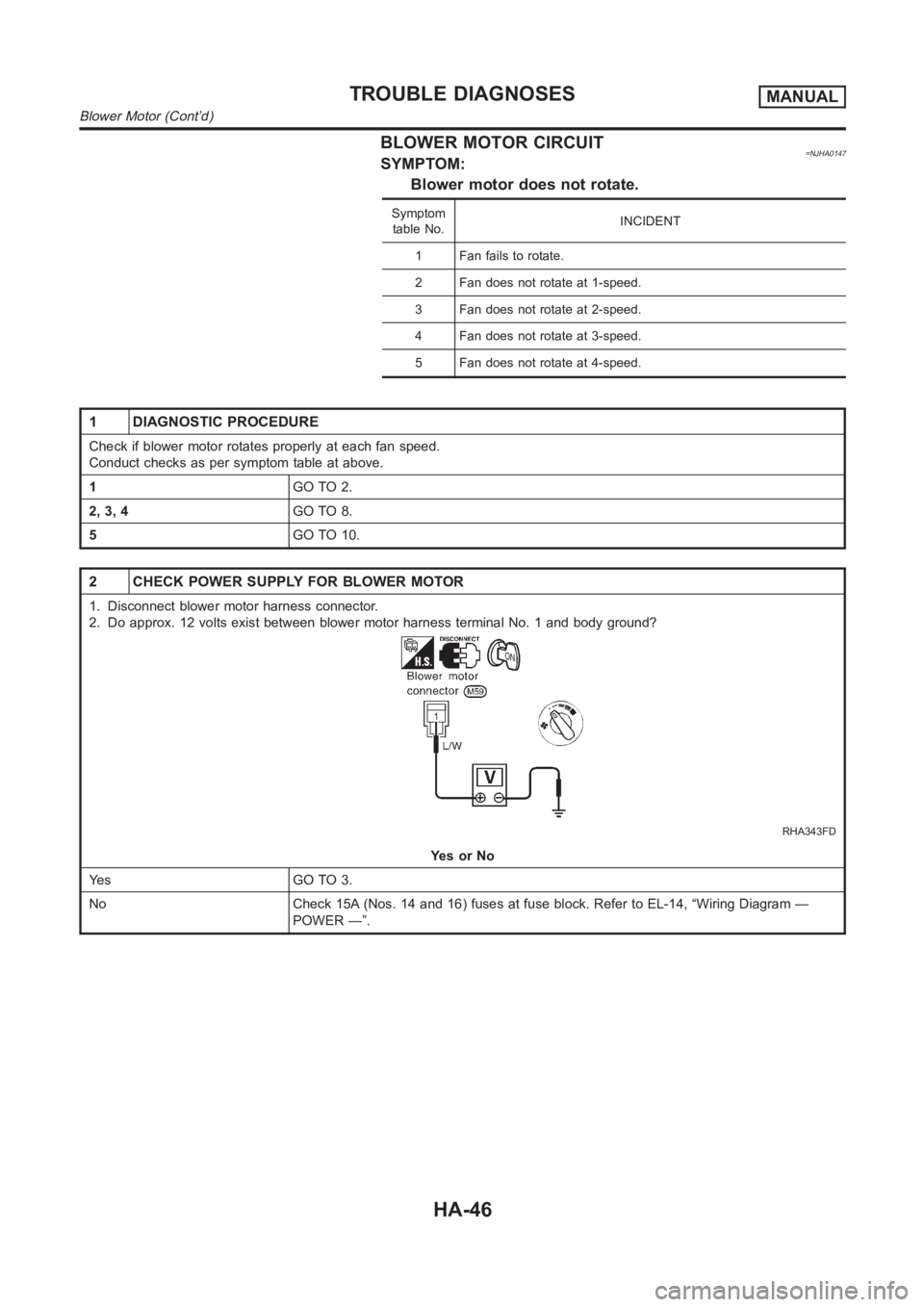
BLOWER MOTOR CIRCUIT=NJHA0147SYMPTOM:
Blower motor does not rotate.
Symptom
table No.INCIDENT
1 Fan fails to rotate.
2 Fan does not rotate at 1-speed.
3 Fan does not rotate at 2-speed.
4 Fan does not rotate at 3-speed.
5 Fan does not rotate at 4-speed.
1 DIAGNOSTIC PROCEDURE
Check if blower motor rotates properly at each fan speed.
Conduct checks as per symptom table at above.
1GO TO 2.
2, 3, 4GO TO 8.
5GO TO 10.
2 CHECK POWER SUPPLY FOR BLOWER MOTOR
1. Disconnect blower motor harness connector.
2. Do approx. 12 volts exist between blower motor harness terminal No. 1 andbody ground?
RHA343FD
YesorNo
Ye s G O T O 3 .
No Check 15A (Nos. 14 and 16) fuses at fuse block. Refer to EL-14, “Wiring Diagram —
POWER —”.
TROUBLE DIAGNOSESMANUAL
Blower Motor (Cont’d)
HA-46
Page 2983 of 3189
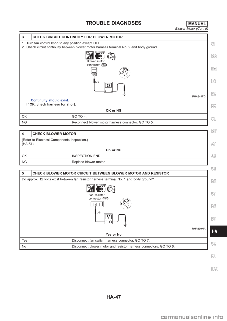
3 CHECK CIRCUIT CONTINUITY FOR BLOWER MOTOR
1. Turn fan control knob to any position except OFF.
2. Check circuit continuity between blower motor harness terminal No. 2 and body ground.
RHA344FD
Continuity should exist.
If OK, check harness for short.
OK or NG
OK GO TO 4.
NG Reconnect blower motor harness connector. GO TO 5.
4 CHECK BLOWER MOTOR
(Refer to Electrical Components Inspection.)
(HA-51)
OK or NG
OK INSPECTION END
NG Replace blower motor.
5 CHECK BLOWER MOTOR CIRCUIT BETWEEN BLOWER MOTOR AND RESISTOR
Do approx. 12 volts exist between fan resistor harness terminal No. 1 and body ground?
RHA699HA
YesorNo
Yes Disconnect fan switch harness connector. GO TO 7.
No Disconnect blower motor and resistor harness connectors. GO TO 6.
GI
MA
EM
LC
EC
FE
CL
MT
AT
AX
SU
BR
ST
RS
BT
SC
EL
IDX
TROUBLE DIAGNOSESMANUAL
Blower Motor (Cont’d)
HA-47
Page 2984 of 3189
6 CHECK CIRCUIT CONTINUITY BETWEEN BLOWER MOTOR AND RESISTOR
Check circuit continuity between blower motor harness terminal No. 2 and fan resistor harness terminal No. 1.
RHA700HA
Continuity should exist.
If OK, check harness for short.
OK or NG
OK Poor contact between the resistor and blower motor connector.
NG Repair harness or connector.
7 CHECK GROUND CIRCUIT FOR HEATER CONTROL PANEL
Check circuit continuity between fan switch harness terminal No. 13 and body ground.
NHA506
Continuity should exist.
If OK, check harness for short.
OK or NG
OK GO TO 8.
NG Repair harness or connector.
8 CHECK RESISTOR AFTER DISCONNECTING IT
(Refer to Electrical Components Inspection.)
(HA-51)
OK or NG
OK GO TO 9.
NG Replace resistor.
9 CHECK RESISTOR HARNESS CONNECTOR
Reconnect resistor harness connector.
OK or NG
1GO TO 12.
2, 3, 4GO TO 10.
TROUBLE DIAGNOSESMANUAL
Blower Motor (Cont’d)
HA-48
Page 2985 of 3189
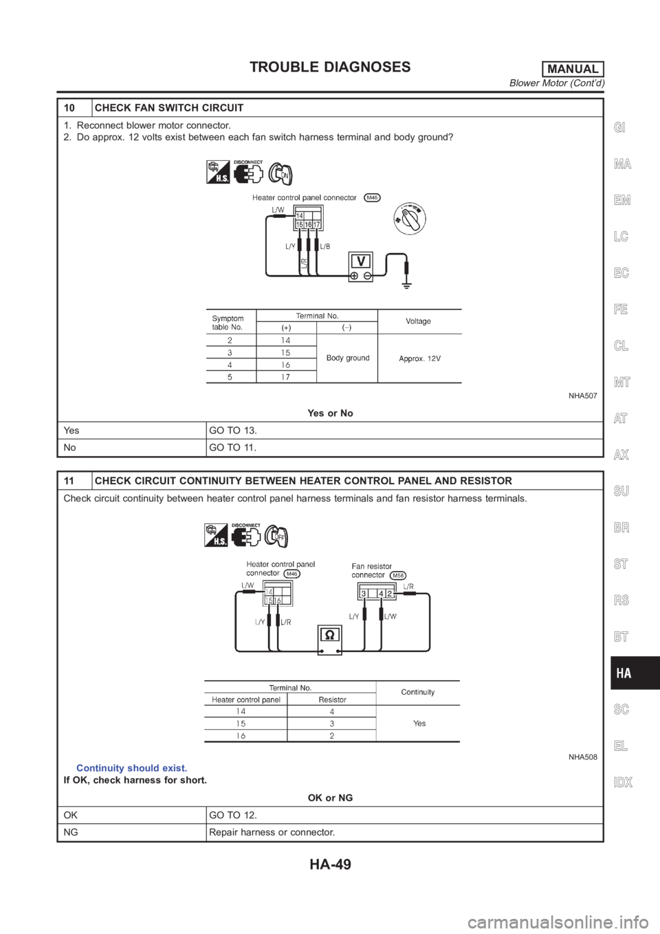
10 CHECK FAN SWITCH CIRCUIT
1. Reconnect blower motor connector.
2. Do approx. 12 volts exist between each fan switch harness terminal and body ground?
NHA507
YesorNo
Yes GO TO 13.
No GO TO 11.
11 CHECK CIRCUIT CONTINUITY BETWEEN HEATER CONTROL PANEL AND RESISTOR
Check circuit continuity between heater control panel harness terminalsand fan resistor harness terminals.
NHA508
Continuity should exist.
If OK, check harness for short.
OK or NG
OK GO TO 12.
NG Repair harness or connector.
GI
MA
EM
LC
EC
FE
CL
MT
AT
AX
SU
BR
ST
RS
BT
SC
EL
IDX
TROUBLE DIAGNOSESMANUAL
Blower Motor (Cont’d)
HA-49
Page 2986 of 3189
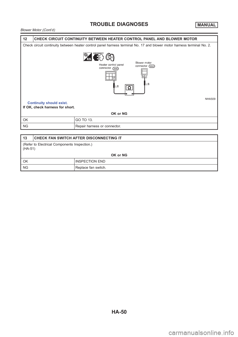
12 CHECK CIRCUIT CONTINUITY BETWEEN HEATER CONTROL PANEL AND BLOWER MOTOR
Check circuit continuity between heater control panel harness terminal No. 17 and blower motor harness terminal No. 2.
NHA509
Continuity should exist.
If OK, check harness for short.
OK or NG
OK GO TO 13.
NG Repair harness or connector.
13 CHECK FAN SWITCH AFTER DISCONNECTING IT
(Refer to Electrical Components Inspection.)
(HA-51)
OK or NG
OK INSPECTION END
NG Replace fan switch.
TROUBLE DIAGNOSESMANUAL
Blower Motor (Cont’d)
HA-50
Page 2987 of 3189
NHA386
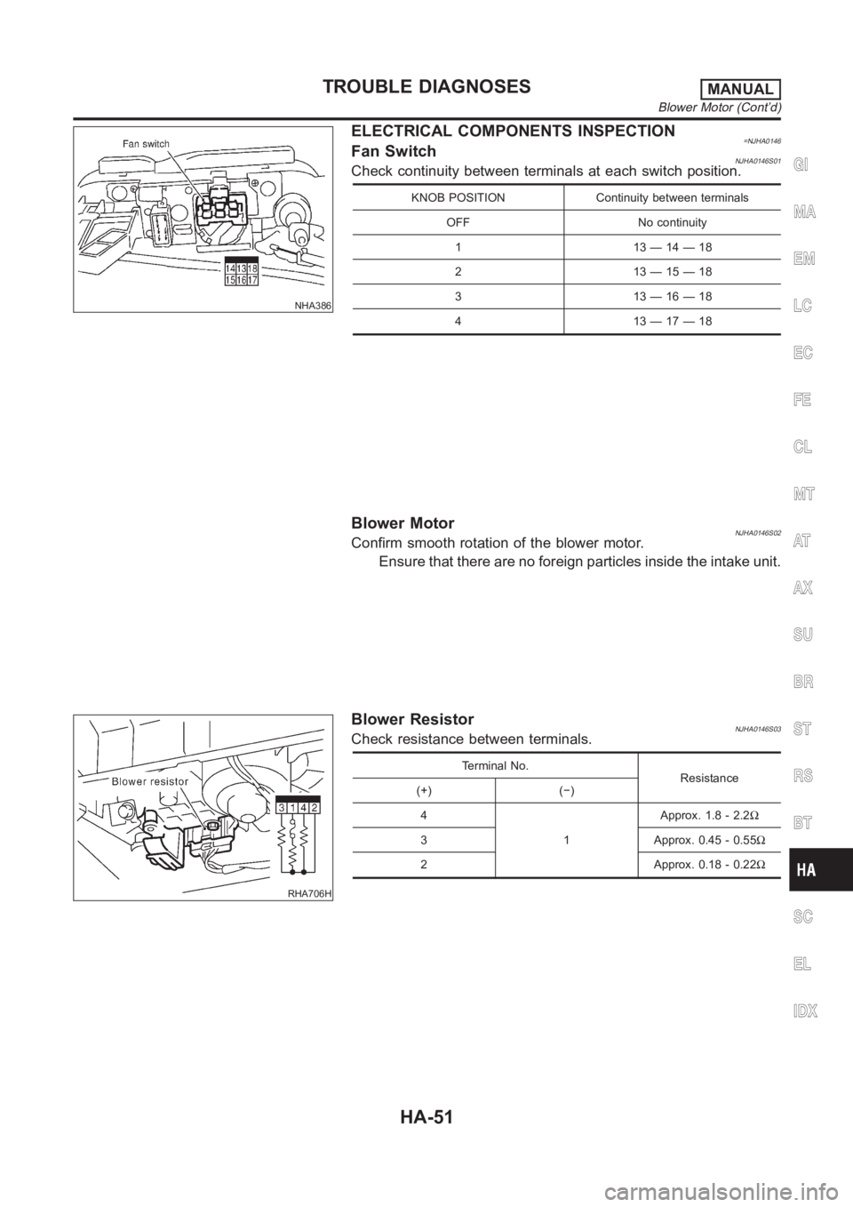
ELECTRICAL COMPONENTS INSPECTION=NJHA0146Fan SwitchNJHA0146S01Check continuity between terminals at each switch position.
KNOB POSITION Continuity between terminals
OFF No continuity
113—14—18
213—15—18
313—16—18
413—17—18
Blower MotorNJHA0146S02Confirm smooth rotation of the blower motor.
Ensure that there are no foreign particles inside the intake unit.
RHA706H
Blower ResistorNJHA0146S03Check resistance between terminals.
Terminal No.
Resistance
(+) (−)
4
1Approx. 1.8 - 2.2Ω
3 Approx. 0.45 - 0.55Ω
2 Approx. 0.18 - 0.22Ω
GI
MA
EM
LC
EC
FE
CL
MT
AT
AX
SU
BR
ST
RS
BT
SC
EL
IDX
TROUBLE DIAGNOSESMANUAL
Blower Motor (Cont’d)
HA-51
Page 2988 of 3189
Magnet Clutch
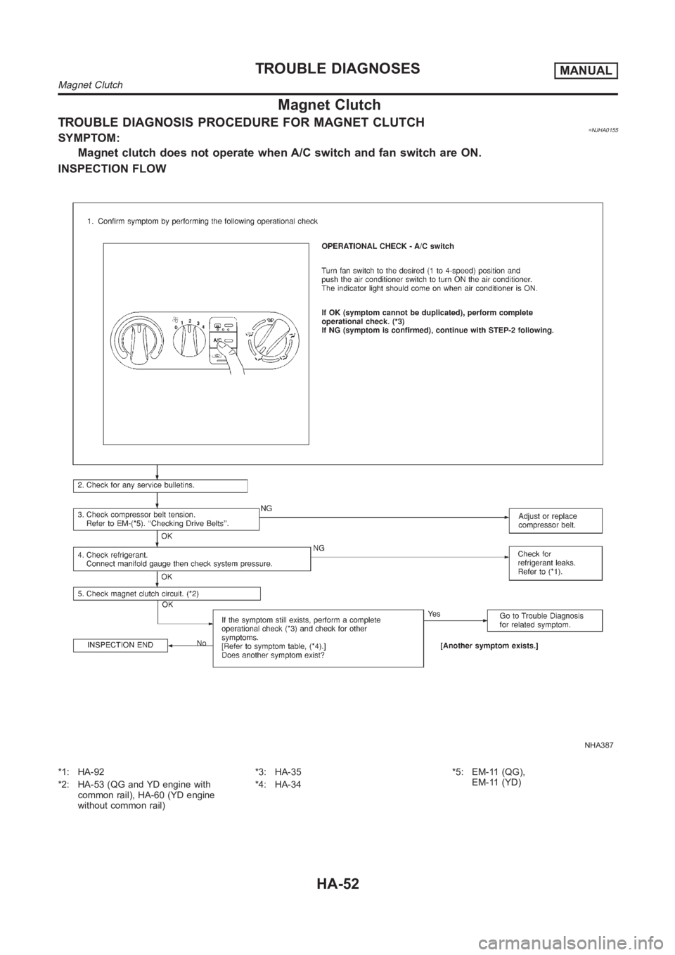
TROUBLE DIAGNOSIS PROCEDURE FOR MAGNET CLUTCH=NJHA0155SYMPTOM:
Magnet clutch does not operate when A/C switch and fan switch are ON.
INSPECTION FLOW
NHA387
*1: HA-92
*2: HA-53 (QG and YD engine with
common rail), HA-60 (YD engine
without common rail)*3: HA-35
*4: HA-34*5: EM-11 (QG),
EM-11 (YD)
TROUBLE DIAGNOSESMANUAL
Magnet Clutch
HA-52
Page 2989 of 3189
MAGNET CLUTCH CIRCUIT (QG ENGINE AND YD
ENGINE WITH COMMON RAIL)
=NJHA0156SYMPTOM:
Magnet clutch does not engage when A/C switch and fan
switch are ON.
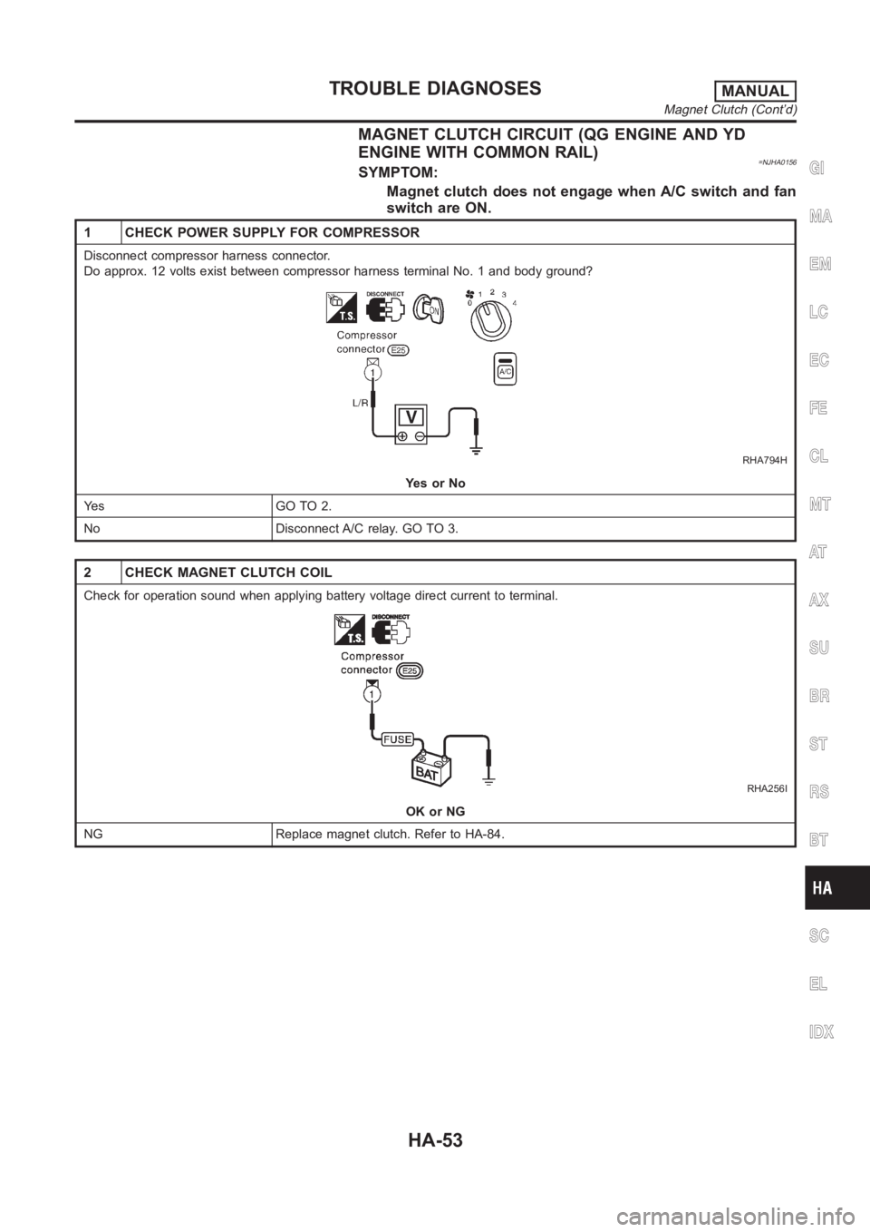
1 CHECK POWER SUPPLY FOR COMPRESSOR
Disconnect compressor harness connector.
Do approx. 12 volts exist between compressor harness terminal No. 1 and body ground?
RHA794H
YesorNo
Ye s G O T O 2 .
No Disconnect A/C relay. GO TO 3.
2 CHECK MAGNET CLUTCH COIL
Check for operation sound when applying battery voltage direct current toterminal.
RHA256I
OK or NG
NG Replace magnet clutch. Refer to HA-84.
GI
MA
EM
LC
EC
FE
CL
MT
AT
AX
SU
BR
ST
RS
BT
SC
EL
IDX
TROUBLE DIAGNOSESMANUAL
Magnet Clutch (Cont’d)
HA-53
Page 2990 of 3189
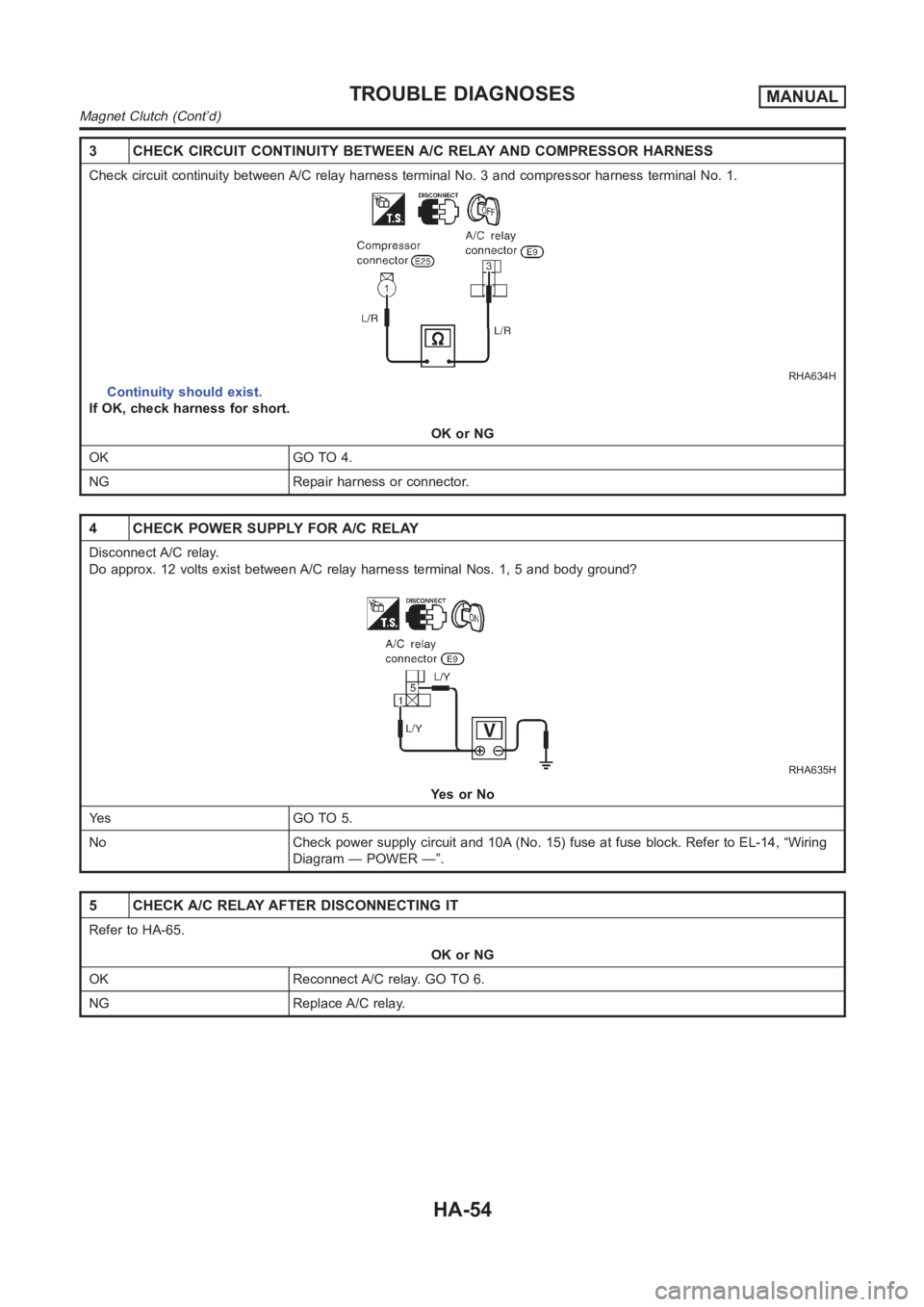
3 CHECK CIRCUIT CONTINUITY BETWEEN A/C RELAY AND COMPRESSOR HARNESS
Check circuit continuity between A/C relay harness terminal No. 3 and compressor harness terminal No. 1.
RHA634H
Continuity should exist.
If OK, check harness for short.
OK or NG
OK GO TO 4.
NG Repair harness or connector.
4 CHECK POWER SUPPLY FOR A/C RELAY
Disconnect A/C relay.
Do approx. 12 volts exist between A/C relay harness terminal Nos. 1, 5 and body ground?
RHA635H
YesorNo
Ye s G O T O 5 .
No Check power supply circuit and 10A (No. 15) fuse at fuse block. Refer to EL-14, “Wiring
Diagram — POWER —”.
5 CHECK A/C RELAY AFTER DISCONNECTING IT
Refer to HA-65.
OK or NG
OK Reconnect A/C relay. GO TO 6.
NG Replace A/C relay.
TROUBLE DIAGNOSESMANUAL
Magnet Clutch (Cont’d)
HA-54
Trending: restraint, Engine harness, navigation system, charging, electrical system, transmission oil, Engine wiring
