NISSAN ALMERA TINO 2001 Service Repair Manual
Manufacturer: NISSAN, Model Year: 2001, Model line: ALMERA TINO, Model: NISSAN ALMERA TINO 2001Pages: 3051, PDF Size: 46.38 MB
Page 1241 of 3051
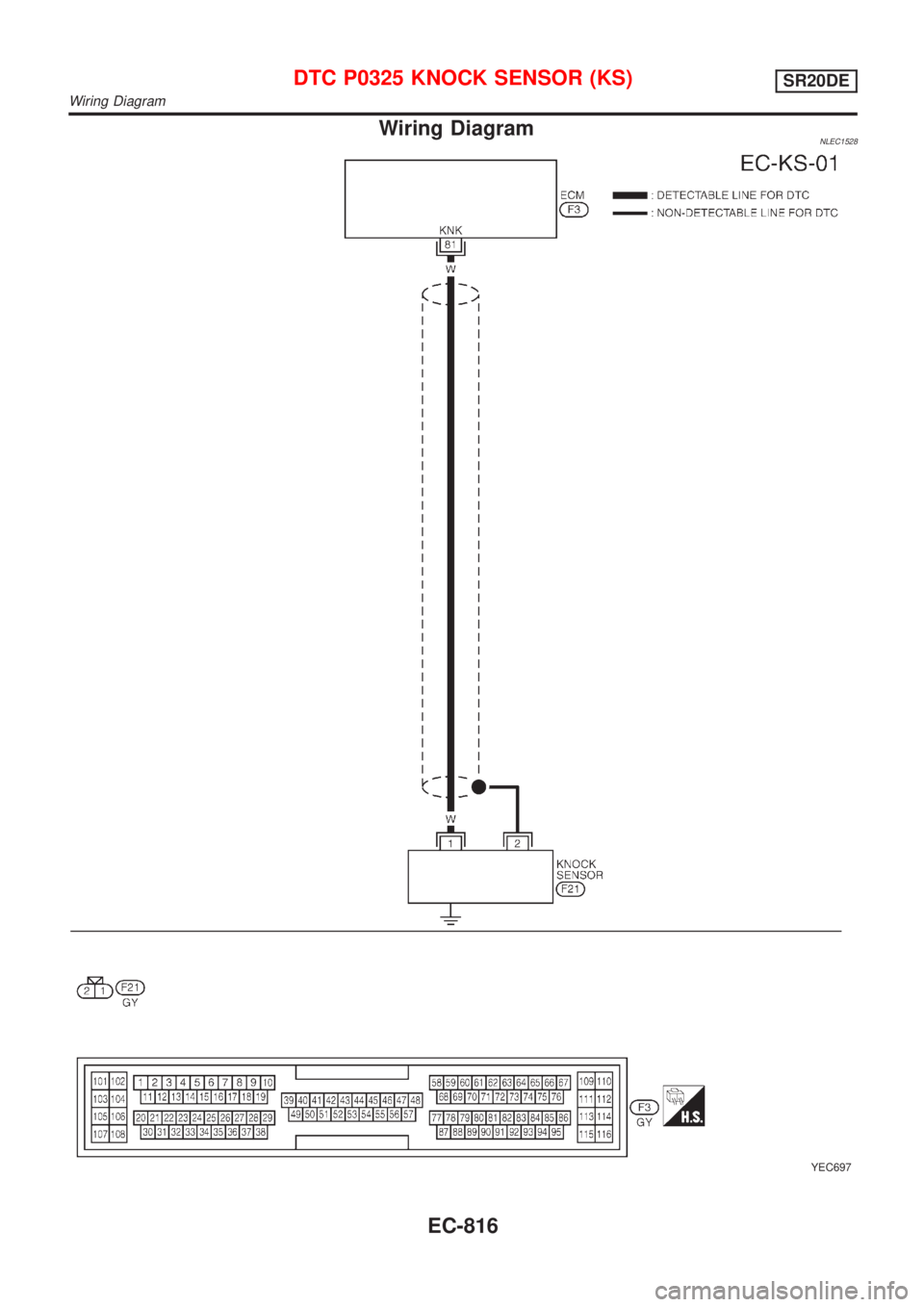
Wiring DiagramNLEC1528
YEC697
DTC P0325 KNOCK SENSOR (KS)SR20DE
Wiring Diagram
EC-816
Page 1242 of 3051
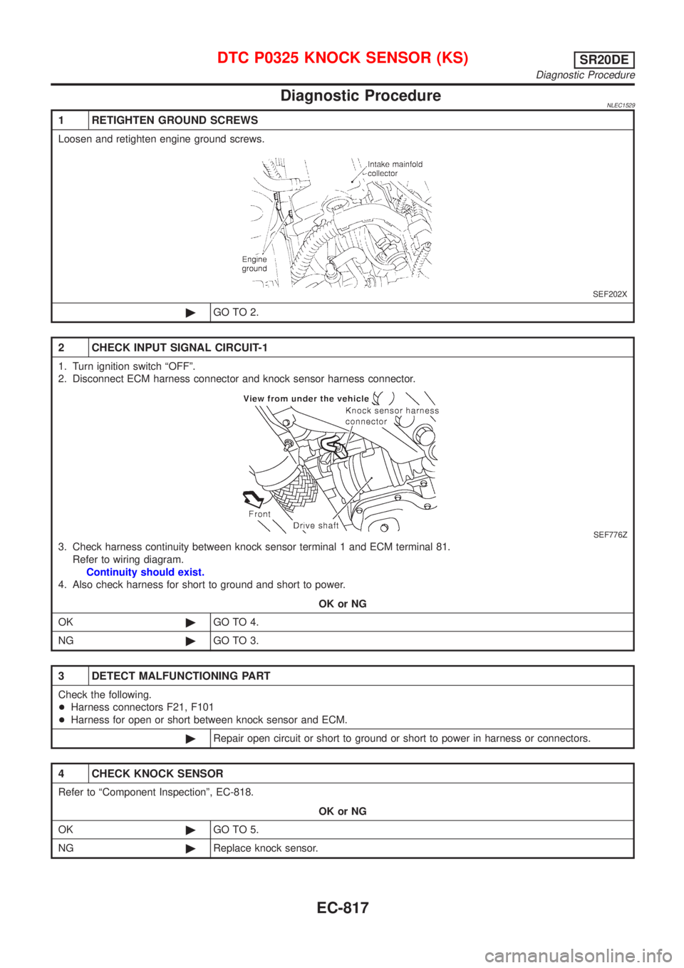
Diagnostic ProcedureNLEC1529
1 RETIGHTEN GROUND SCREWS
Loosen and retighten engine ground screws.
SEF202X
©GO TO 2.
2 CHECK INPUT SIGNAL CIRCUIT-1
1. Turn ignition switch ªOFFº.
2. Disconnect ECM harness connector and knock sensor harness connector.
SEF776Z
3. Check harness continuity between knock sensor terminal 1 and ECM terminal 81.
Refer to wiring diagram.
Continuity should exist.
4. Also check harness for short to ground and short to power.
OK or NG
OK©GO TO 4.
NG©GO TO 3.
3 DETECT MALFUNCTIONING PART
Check the following.
+Harness connectors F21, F101
+Harness for open or short between knock sensor and ECM.
©Repair open circuit or short to ground or short to power in harness or connectors.
4 CHECK KNOCK SENSOR
Refer to ªComponent Inspectionº, EC-818.
OK or NG
OK©GO TO 5.
NG©Replace knock sensor.
DTC P0325 KNOCK SENSOR (KS)SR20DE
Diagnostic Procedure
EC-817
Page 1243 of 3051
5 CHECK SHIELD CIRCUIT
1. Reconnect harness connectors disconnected.
2. Disconnect harness connectors F21, F101.
3. Check harness continuity between F21 terminal 2 and engine ground.
Refer to wiring diagram.
Continuity should exist.
4. Also check harness for short to power.
5. Then reconnect harness connectors.
OK or NG
OK©GO TO 6.
NG©Repair open circuit or short to power in harness or connectors.
6 CHECK INTERMITTENT INCIDENT
Perform ªTROUBLE DIAGNOSIS FOR INTERMITTENT INCIDENTº, EC-670.
©INSPECTION END
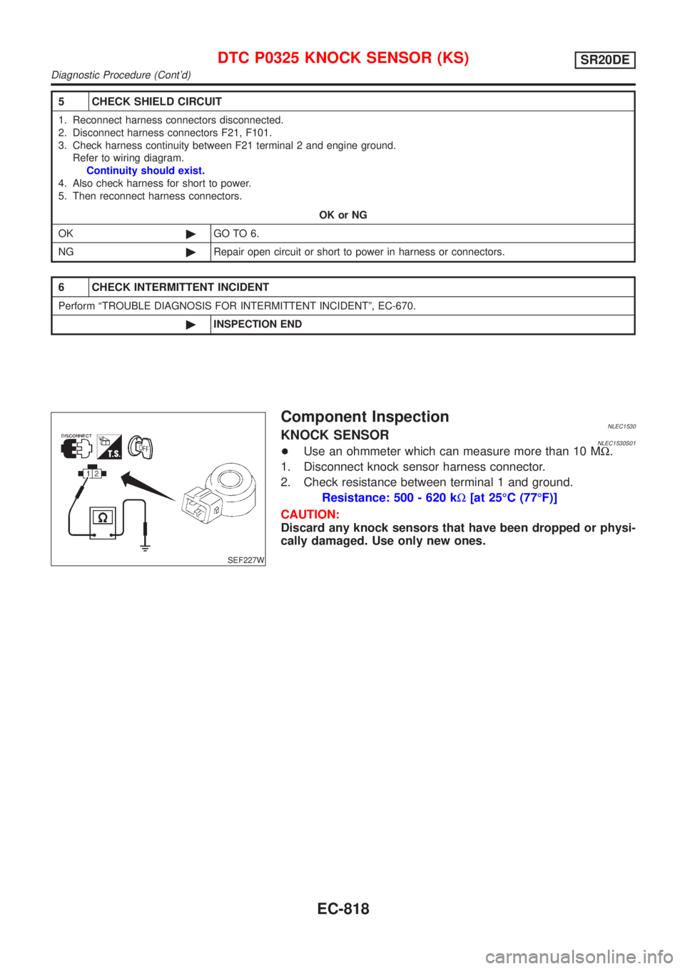
SEF227W
Component InspectionNLEC1530KNOCK SENSORNLEC1530S01+Use an ohmmeter which can measure more than 10 MW.
1. Disconnect knock sensor harness connector.
2. Check resistance between terminal 1 and ground.
Resistance: 500 - 620 kW[at 25ÉC (77ÉF)]
CAUTION:
Discard any knock sensors that have been dropped or physi-
cally damaged. Use only new ones.
DTC P0325 KNOCK SENSOR (KS)SR20DE
Diagnostic Procedure (Cont'd)
EC-818
Page 1244 of 3051
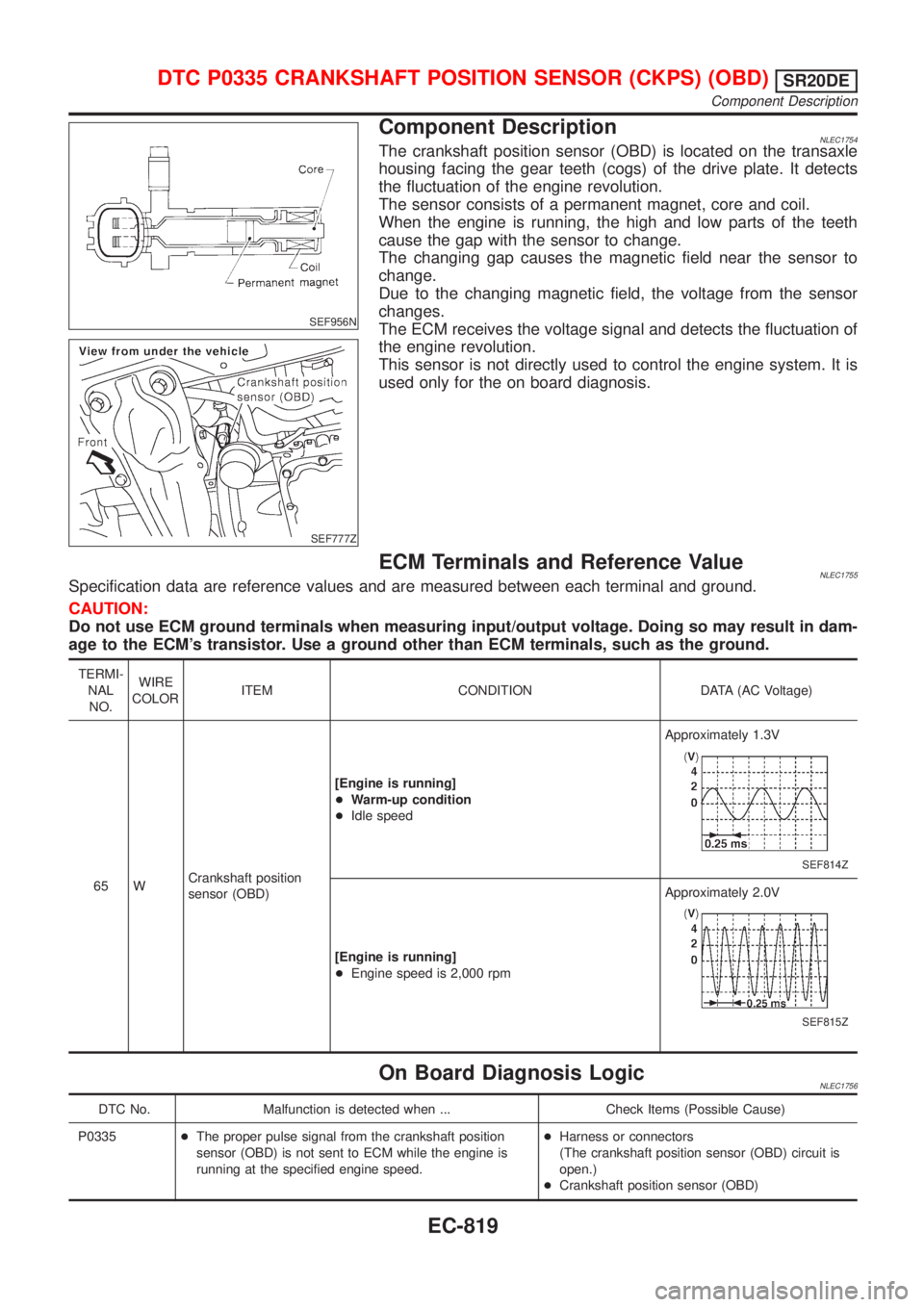
SEF956N
SEF777Z
Component DescriptionNLEC1754The crankshaft position sensor (OBD) is located on the transaxle
housing facing the gear teeth (cogs) of the drive plate. It detects
the fluctuation of the engine revolution.
The sensor consists of a permanent magnet, core and coil.
When the engine is running, the high and low parts of the teeth
cause the gap with the sensor to change.
The changing gap causes the magnetic field near the sensor to
change.
Due to the changing magnetic field, the voltage from the sensor
changes.
The ECM receives the voltage signal and detects the fluctuation of
the engine revolution.
This sensor is not directly used to control the engine system. It is
used only for the on board diagnosis.
ECM Terminals and Reference ValueNLEC1755Specification data are reference values and are measured between each terminal and ground.
CAUTION:
Do not use ECM ground terminals when measuring input/output voltage. Doing so may result in dam-
age to the ECM's transistor. Use a ground other than ECM terminals, such as the ground.
TERMI-
NAL
NO.WIRE
COLORITEM CONDITION DATA (AC Voltage)
65 WCrankshaft position
sensor (OBD)[Engine is running]
+Warm-up condition
+Idle speedApproximately 1.3V
SEF814Z
[Engine is running]
+Engine speed is 2,000 rpmApproximately 2.0V
SEF815Z
On Board Diagnosis LogicNLEC1756
DTC No. Malfunction is detected when ... Check Items (Possible Cause)
P0335+The proper pulse signal from the crankshaft position
sensor (OBD) is not sent to ECM while the engine is
running at the specified engine speed.+Harness or connectors
(The crankshaft position sensor (OBD) circuit is
open.)
+Crankshaft position sensor (OBD)
DTC P0335 CRANKSHAFT POSITION SENSOR (CKPS) (OBD)SR20DE
Component Description
EC-819
Page 1245 of 3051

SEF058Y
DTC Confirmation ProcedureNLEC1757NOTE:
If ªDTC Confirmation Procedureº has been previously conducted,
always turn ignition switch ªOFFº and wait at least 10 seconds
before conducting the next test.
With CONSULT-II
1) Turn ignition switch ªONº and select ªDATA MONITORº mode
with CONSULT-II.
2) Start engine and run it for at least 10 seconds at idle speed.
3) If 1st trip DTC is detected, go to ªDiagnostic Procedureº,
EC-823.
With GST
Follow the procedure ªWith CONSULT-IIº above.
DTC P0335 CRANKSHAFT POSITION SENSOR (CKPS) (OBD)SR20DE
DTC Confirmation Procedure
EC-820
Page 1246 of 3051
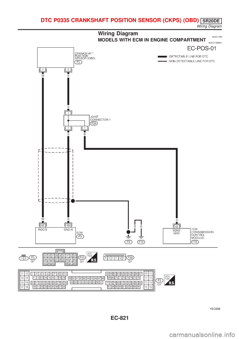
Wiring DiagramNLEC1758MODELS WITH ECM IN ENGINE COMPARTMENTNLEC1758S01
YEC698
DTC P0335 CRANKSHAFT POSITION SENSOR (CKPS) (OBD)SR20DE
Wiring Diagram
EC-821
Page 1247 of 3051
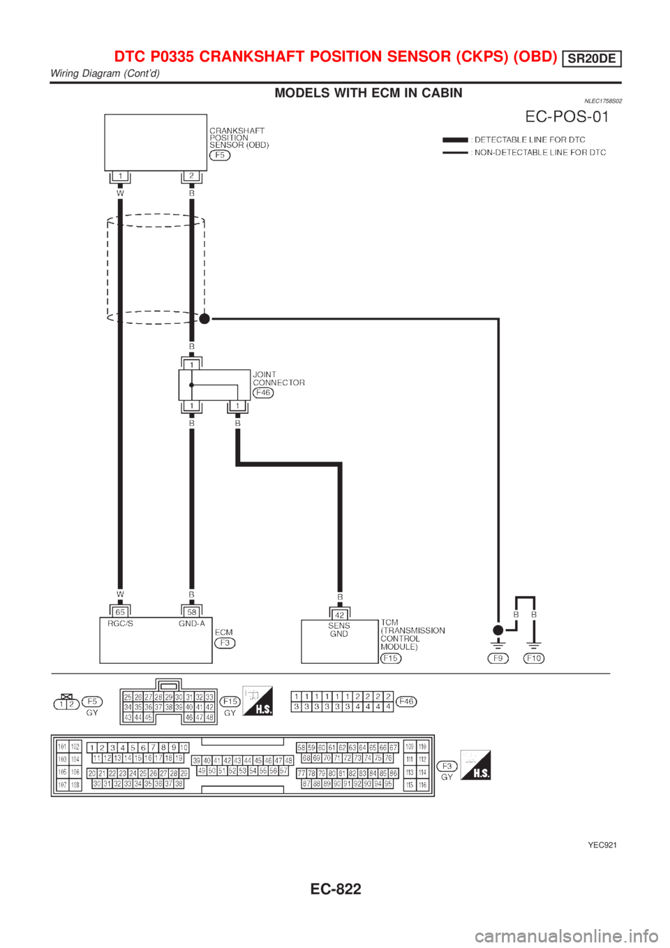
MODELS WITH ECM IN CABINNLEC1758S02
YEC921
DTC P0335 CRANKSHAFT POSITION SENSOR (CKPS) (OBD)SR20DE
Wiring Diagram (Cont'd)
EC-822
Page 1248 of 3051
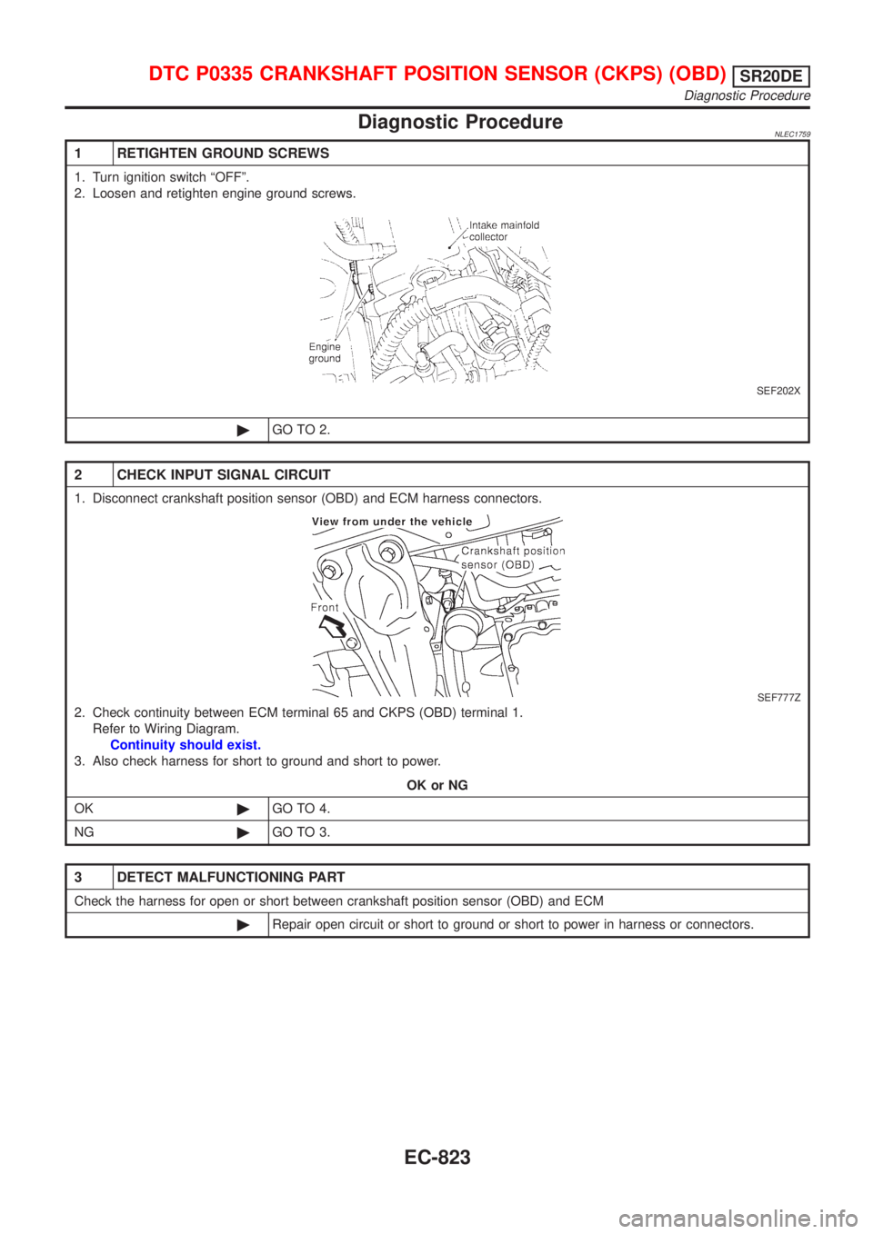
Diagnostic ProcedureNLEC1759
1 RETIGHTEN GROUND SCREWS
1. Turn ignition switch ªOFFº.
2. Loosen and retighten engine ground screws.
SEF202X
©GO TO 2.
2 CHECK INPUT SIGNAL CIRCUIT
1. Disconnect crankshaft position sensor (OBD) and ECM harness connectors.
SEF777Z
2. Check continuity between ECM terminal 65 and CKPS (OBD) terminal 1.
Refer to Wiring Diagram.
Continuity should exist.
3. Also check harness for short to ground and short to power.
OK or NG
OK©GO TO 4.
NG©GO TO 3.
3 DETECT MALFUNCTIONING PART
Check the harness for open or short between crankshaft position sensor (OBD) and ECM
©Repair open circuit or short to ground or short to power in harness or connectors.
DTC P0335 CRANKSHAFT POSITION SENSOR (CKPS) (OBD)SR20DE
Diagnostic Procedure
EC-823
Page 1249 of 3051
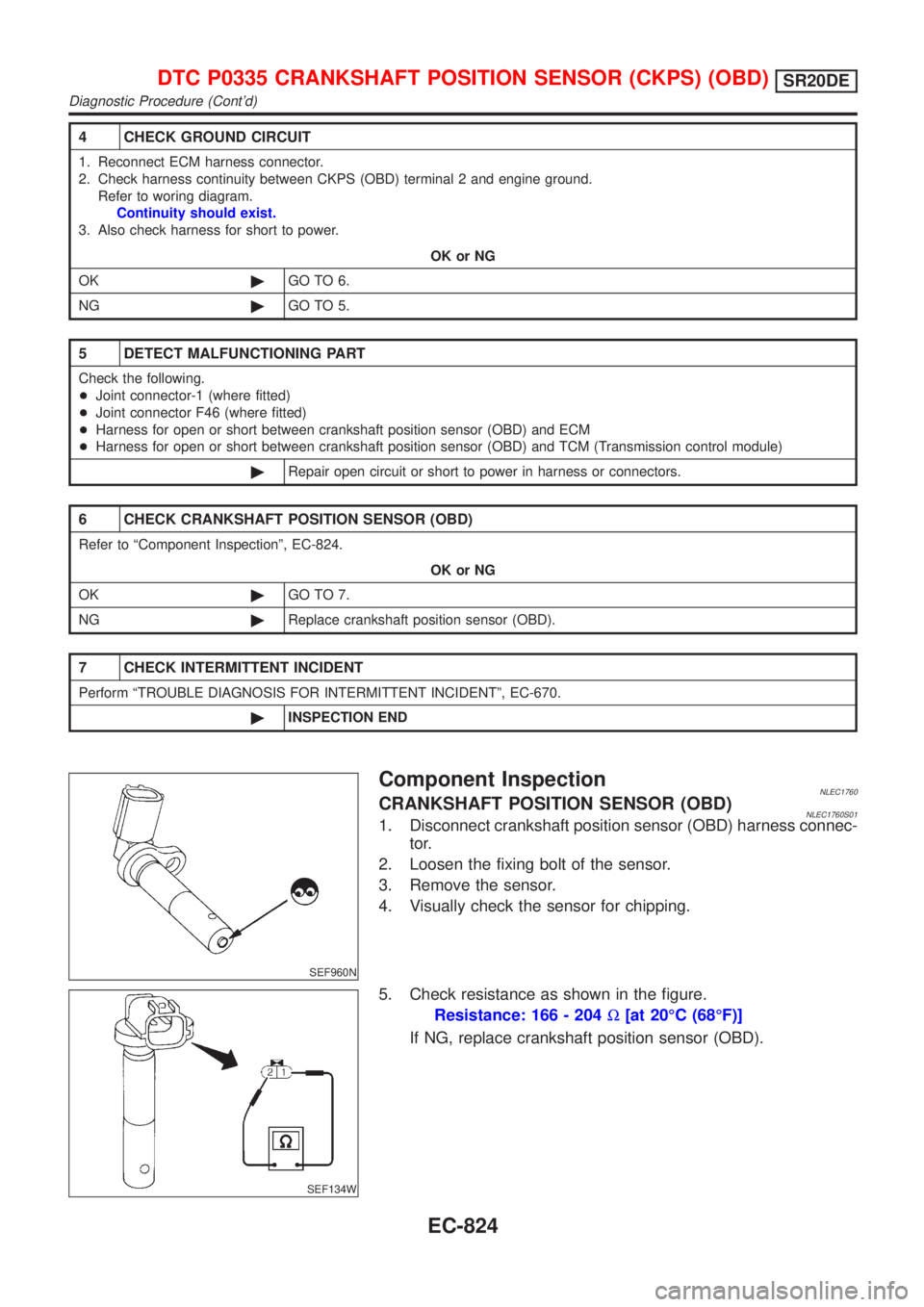
4 CHECK GROUND CIRCUIT
1. Reconnect ECM harness connector.
2. Check harness continuity between CKPS (OBD) terminal 2 and engine ground.
Refer to woring diagram.
Continuity should exist.
3. Also check harness for short to power.
OK or NG
OK©GO TO 6.
NG©GO TO 5.
5 DETECT MALFUNCTIONING PART
Check the following.
+Joint connector-1 (where fitted)
+Joint connector F46 (where fitted)
+Harness for open or short between crankshaft position sensor (OBD) and ECM
+Harness for open or short between crankshaft position sensor (OBD) and TCM (Transmission control module)
©Repair open circuit or short to power in harness or connectors.
6 CHECK CRANKSHAFT POSITION SENSOR (OBD)
Refer to ªComponent Inspectionº, EC-824.
OK or NG
OK©GO TO 7.
NG©Replace crankshaft position sensor (OBD).
7 CHECK INTERMITTENT INCIDENT
Perform ªTROUBLE DIAGNOSIS FOR INTERMITTENT INCIDENTº, EC-670.
©INSPECTION END
SEF960N
Component InspectionNLEC1760CRANKSHAFT POSITION SENSOR (OBD)NLEC1760S011. Disconnect crankshaft position sensor (OBD) harness connec-
tor.
2. Loosen the fixing bolt of the sensor.
3. Remove the sensor.
4. Visually check the sensor for chipping.
SEF134W
5. Check resistance as shown in the figure.
Resistance: 166 - 204W[at 20ÉC (68ÉF)]
If NG, replace crankshaft position sensor (OBD).
DTC P0335 CRANKSHAFT POSITION SENSOR (CKPS) (OBD)SR20DE
Diagnostic Procedure (Cont'd)
EC-824
Page 1250 of 3051
SEF998R
SEF853B
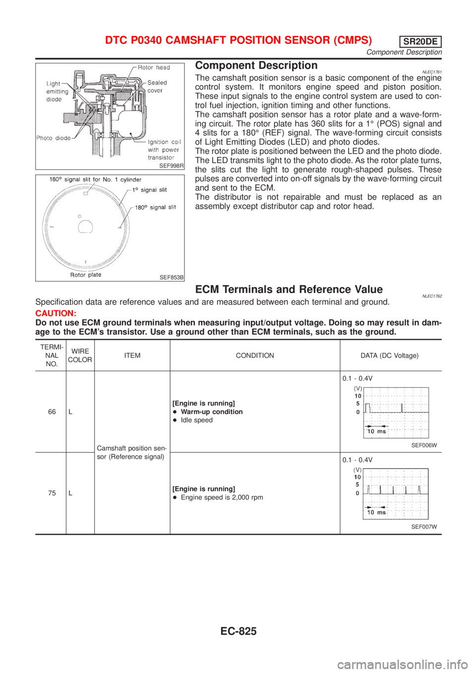
Component DescriptionNLEC1761The camshaft position sensor is a basic component of the engine
control system. It monitors engine speed and piston position.
These input signals to the engine control system are used to con-
trol fuel injection, ignition timing and other functions.
The camshaft position sensor has a rotor plate and a wave-form-
ing circuit. The rotor plate has 360 slits for a 1É (POS) signal and
4 slits for a 180É (REF) signal. The wave-forming circuit consists
of Light Emitting Diodes (LED) and photo diodes.
The rotor plate is positioned between the LED and the photo diode.
The LED transmits light to the photo diode. As the rotor plate turns,
the slits cut the light to generate rough-shaped pulses. These
pulses are converted into on-off signals by the wave-forming circuit
and sent to the ECM.
The distributor is not repairable and must be replaced as an
assembly except distributor cap and rotor head.
ECM Terminals and Reference ValueNLEC1762Specification data are reference values and are measured between each terminal and ground.
CAUTION:
Do not use ECM ground terminals when measuring input/output voltage. Doing so may result in dam-
age to the ECM's transistor. Use a ground other than ECM terminals, such as the ground.
TERMI-
NAL
NO.WIRE
COLORITEM CONDITION DATA (DC Voltage)
66 L
Camshaft position sen-
sor (Reference signal)[Engine is running]
+Warm-up condition
+Idle speed0.1 - 0.4V
SEF006W
75 L[Engine is running]
+Engine speed is 2,000 rpm0.1 - 0.4V
SEF007W
DTC P0340 CAMSHAFT POSITION SENSOR (CMPS)SR20DE
Component Description
EC-825