NISSAN ALMERA TINO 2001 Service Repair Manual
Manufacturer: NISSAN, Model Year: 2001, Model line: ALMERA TINO, Model: NISSAN ALMERA TINO 2001Pages: 3051, PDF Size: 46.38 MB
Page 1671 of 3051
SEF437Y
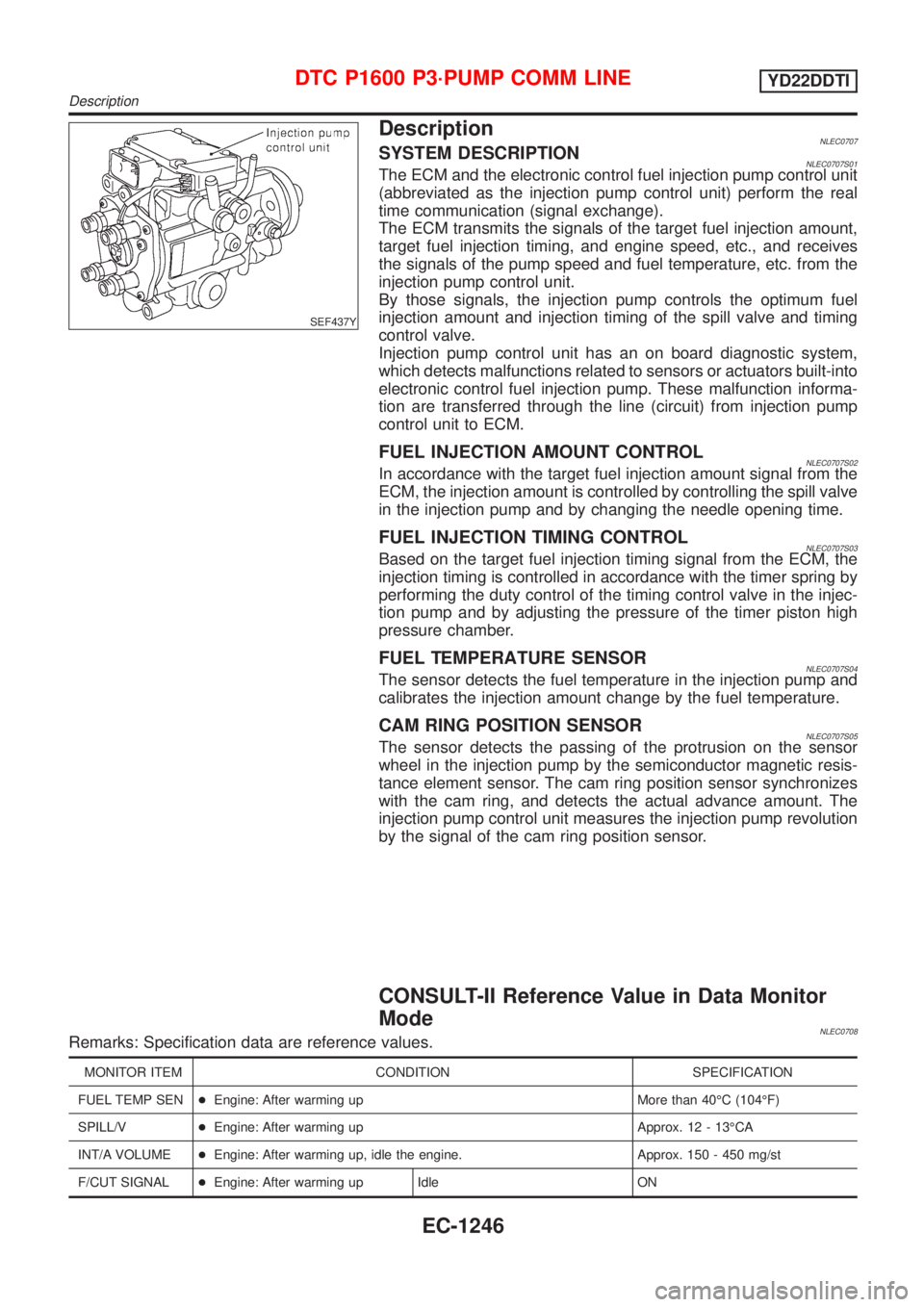
DescriptionNLEC0707SYSTEM DESCRIPTIONNLEC0707S01The ECM and the electronic control fuel injection pump control unit
(abbreviated as the injection pump control unit) perform the real
time communication (signal exchange).
The ECM transmits the signals of the target fuel injection amount,
target fuel injection timing, and engine speed, etc., and receives
the signals of the pump speed and fuel temperature, etc. from the
injection pump control unit.
By those signals, the injection pump controls the optimum fuel
injection amount and injection timing of the spill valve and timing
control valve.
Injection pump control unit has an on board diagnostic system,
which detects malfunctions related to sensors or actuators built-into
electronic control fuel injection pump. These malfunction informa-
tion are transferred through the line (circuit) from injection pump
control unit to ECM.
FUEL INJECTION AMOUNT CONTROLNLEC0707S02In accordance with the target fuel injection amount signal from the
ECM, the injection amount is controlled by controlling the spill valve
in the injection pump and by changing the needle opening time.
FUEL INJECTION TIMING CONTROLNLEC0707S03Based on the target fuel injection timing signal from the ECM, the
injection timing is controlled in accordance with the timer spring by
performing the duty control of the timing control valve in the injec-
tion pump and by adjusting the pressure of the timer piston high
pressure chamber.
FUEL TEMPERATURE SENSORNLEC0707S04The sensor detects the fuel temperature in the injection pump and
calibrates the injection amount change by the fuel temperature.
CAM RING POSITION SENSORNLEC0707S05The sensor detects the passing of the protrusion on the sensor
wheel in the injection pump by the semiconductor magnetic resis-
tance element sensor. The cam ring position sensor synchronizes
with the cam ring, and detects the actual advance amount. The
injection pump control unit measures the injection pump revolution
by the signal of the cam ring position sensor.
CONSULT-II Reference Value in Data Monitor
Mode
NLEC0708Remarks: Specification data are reference values.
MONITOR ITEM CONDITION SPECIFICATION
FUEL TEMP SEN+Engine: After warming up More than 40ÉC (104ÉF)
SPILL/V+Engine: After warming up Approx. 12 - 13ÉCA
INT/A VOLUME+Engine: After warming up, idle the engine. Approx. 150 - 450 mg/st
F/CUT SIGNAL+Engine: After warming up Idle ON
DTC P1600 P3´PUMP COMM LINEYD22DDTI
Description
EC-1246
Page 1672 of 3051
MONITOR ITEM CONDITION SPECIFICATION
BARO SEN+Ignition switch: ONAltitude
Approx.0m(0ft): Approx. 100.62
kPa (1.0062 bar, 1.026 kg/cm
2,
14.59 psi)
Approx. 1,000 m (3,281 ft): Approx.
88.95 kPa (0.8895 bar, 0.907
kg/cm
2, 12.90 psi)
Approx. 1,500 m (4,922 ft): Approx.
83.16 kPa (0.8316 bar, 0.848
kg/cm
2, 12.06 psi)
Approx. 2,000 m (6,562 ft): Approx.
78.36 kPa (0.7836 bar, 0.799
kg/cm
2, 11.36 psi)
ECM Terminals and Reference ValueNLEC0709Specification data are reference values and are measured between each terminal and ground.
CAUTION:
Do not use ECM ground terminals when measuring input/output voltage. Doing so may result in dam-
age to the ECM's transistor. Use a ground other than ECM terminals, such as the ground.
TERMI-
NAL
NO.WIRE
COLORITEM CONDITION DATA (DC Voltage)
313 L/WElectronic control fuel
injection pump[Engine is running]
+Warm-up condition
+Idle speedApproximately 0.1V
314 L/RElectronic control fuel
injection pump[Engine is running]
+Warm-up condition
+Idle speedApproximately 0.4V
316 PUElectronic control fuel
injection pump[Engine is running]
+Warm-up condition
+Idle speedApproximately 2.5V
317 PElectronic control fuel
injection pump[Engine is running]
+Warm-up condition
+Idle speedApproximately 2.5V
On Board Diagnosis LogicNLEC0710
DTC Malfunction is detected when .... Check Items (Possible cause)
P1600
0703+Injection pump control unit receives incorrect
voltage signal from ECM continuously.+Harness or connectors
(Electronic control fuel injection pump circuit is
open or shorted.)
+Electronic control fuel injection pump
SEF817Y
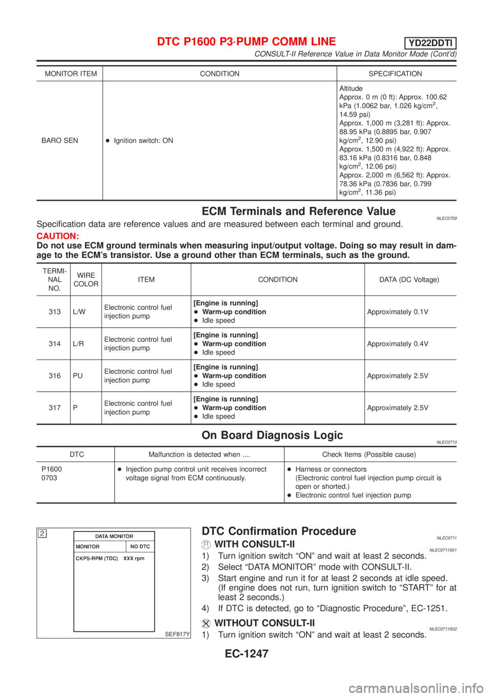
DTC Confirmation ProcedureNLEC0711WITH CONSULT-IINLEC0711S011) Turn ignition switch ªONº and wait at least 2 seconds.
2) Select ªDATA MONITORº mode with CONSULT-II.
3) Start engine and run it for at least 2 seconds at idle speed.
(If engine does not run, turn ignition switch to ªSTARTº for at
least 2 seconds.)
4) If DTC is detected, go to ªDiagnostic Procedureº, EC-1251.
WITHOUT CONSULT-IINLEC0711S021) Turn ignition switch ªONº and wait at least 2 seconds.
DTC P1600 P3´PUMP COMM LINEYD22DDTI
CONSULT-II Reference Value in Data Monitor Mode (Cont'd)
EC-1247
Page 1673 of 3051

2) Start engine and run it for at least 2 seconds at idle speed.
(If engine does not run, turn ignition switch to ªSTARTº for at
least 2 seconds.)
3) Turn ignition switch ªOFFº, wait at least 5 seconds and then
turn ªONº.
4) Perform ªDiagnostic Test Mode II (Self-diagnostic results)º with
ECM.
5) If DTC is detected, go to ªDiagnostic Procedureº, EC-1251.
DTC P1600 P3´PUMP COMM LINEYD22DDTI
DTC Confirmation Procedure (Cont'd)
EC-1248
Page 1674 of 3051
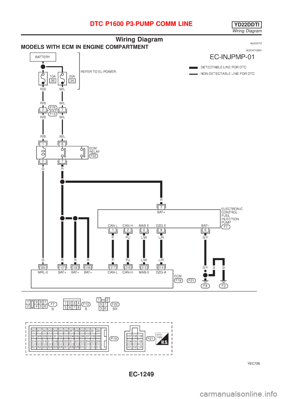
Wiring DiagramNLEC0712MODELS WITH ECM IN ENGINE COMPARTMENTNLEC0712S01
YEC726
DTC P1600 P3´PUMP COMM LINEYD22DDTI
Wiring Diagram
EC-1249
Page 1675 of 3051
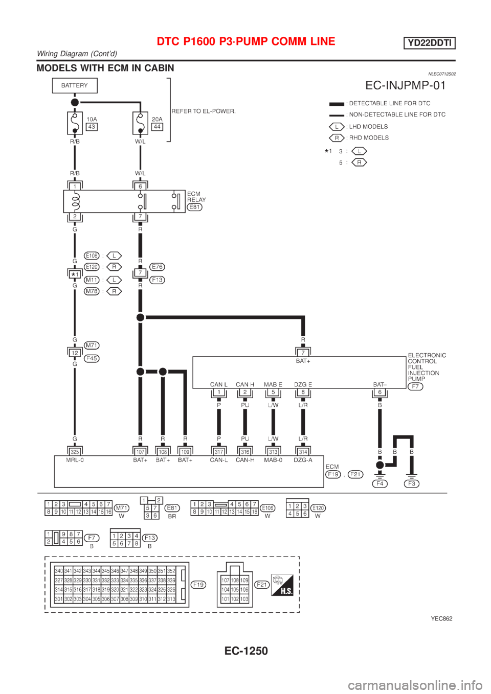
MODELS WITH ECM IN CABINNLEC0712S02
YEC862
DTC P1600 P3´PUMP COMM LINEYD22DDTI
Wiring Diagram (Cont'd)
EC-1250
Page 1676 of 3051
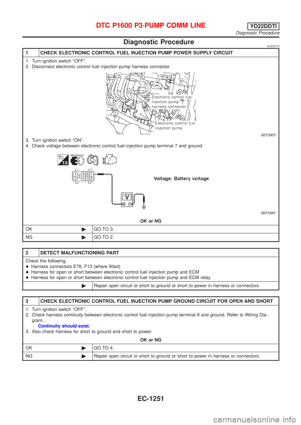
Diagnostic ProcedureNLEC0713
1 CHECK ELECTRONIC CONTROL FUEL INJECTION PUMP POWER SUPPLY CIRCUIT
1. Turn ignition switch ªOFFº.
2. Disconnect electronic control fuel injection pump harness connector.
SEF390Y
3. Turn ignition switch ªONº.
4. Check voltage between electronic control fuel injection pump terminal 7 and ground.
SEF438Y
OK or NG
OK©GO TO 3.
NG©GO TO 2.
2 DETECT MALFUNCTIONING PART
Check the following.
+Harness connectors E76, F13 (where fitted)
+Harness for open or short between electronic control fuel injection pump and ECM
+Harness for open or short between electronic control fuel injection pump and ECM relay
©Repair open circuit or short to ground or short to power in harness or connectors.
3 CHECK ELECTRONIC CONTROL FUEL INJECTION PUMP GROUND CIRCUIT FOR OPEN AND SHORT
1. Turn ignition switch ªOFFº.
2. Check harness continuity between electronic control fuel injection pump terminal 6 and ground. Refer to Wiring Dia-
gram.
Continuity should exist.
3. Also check harness for short to ground and short to power.
OK or NG
OK©GO TO 4.
NG©Repair open circuit or short to ground or short to power in harness or connectors.
DTC P1600 P3´PUMP COMM LINEYD22DDTI
Diagnostic Procedure
EC-1251
Page 1677 of 3051
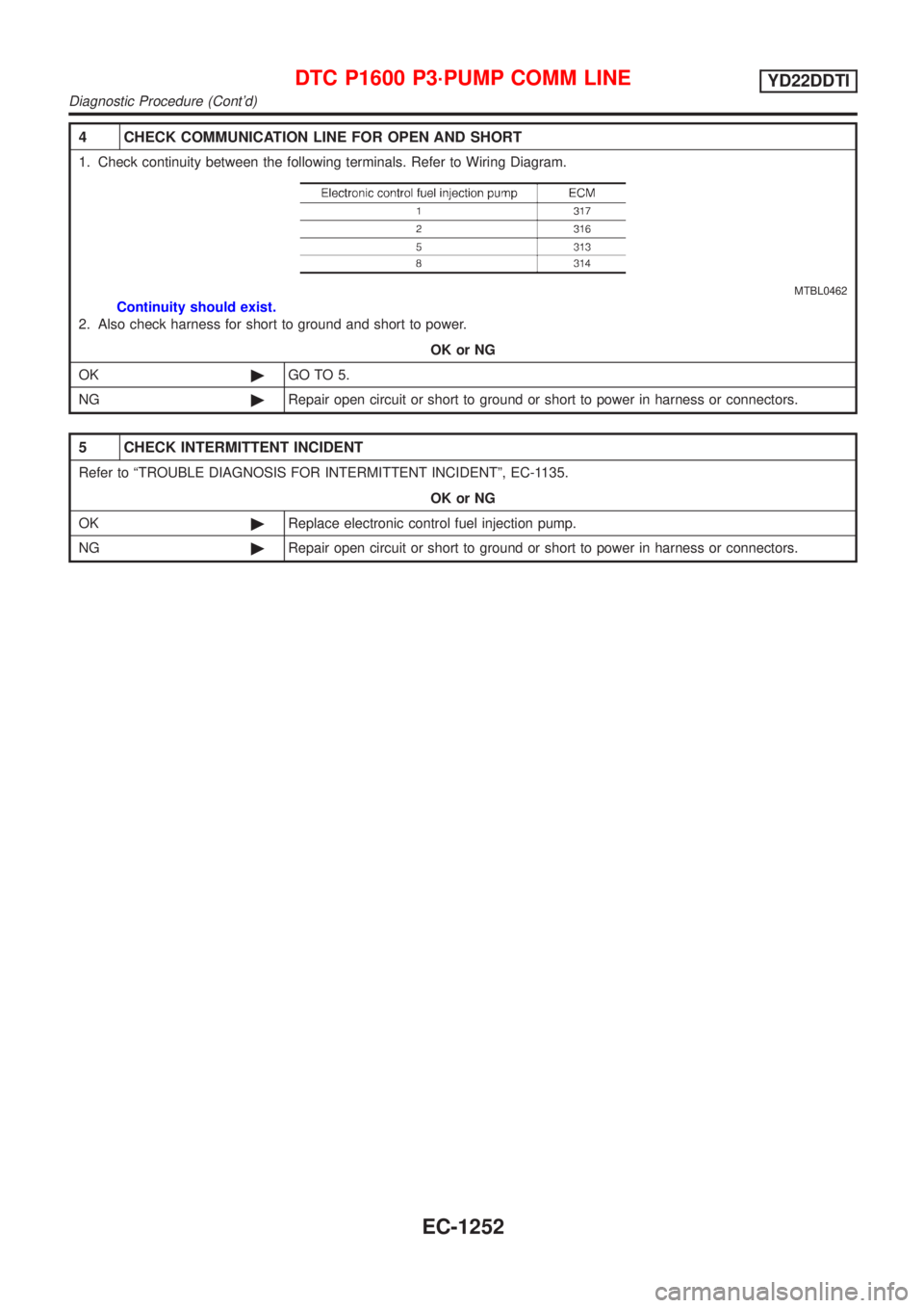
4 CHECK COMMUNICATION LINE FOR OPEN AND SHORT
1. Check continuity between the following terminals. Refer to Wiring Diagram.
MTBL0462
Continuity should exist.
2. Also check harness for short to ground and short to power.
OK or NG
OK©GO TO 5.
NG©Repair open circuit or short to ground or short to power in harness or connectors.
5 CHECK INTERMITTENT INCIDENT
Refer to ªTROUBLE DIAGNOSIS FOR INTERMITTENT INCIDENTº, EC-1135.
OK or NG
OK©Replace electronic control fuel injection pump.
NG©Repair open circuit or short to ground or short to power in harness or connectors.
DTC P1600 P3´PUMP COMM LINEYD22DDTI
Diagnostic Procedure (Cont'd)
EC-1252
Page 1678 of 3051
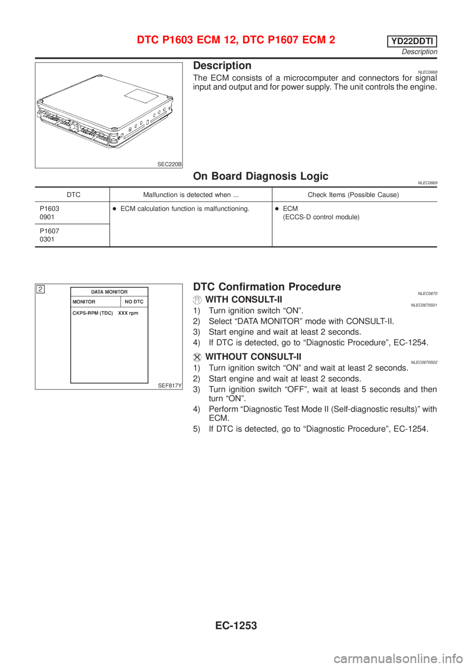
SEC220B
DescriptionNLEC0668The ECM consists of a microcomputer and connectors for signal
input and output and for power supply. The unit controls the engine.
On Board Diagnosis LogicNLEC0669
DTC Malfunction is detected when ... Check Items (Possible Cause)
P1603
0901+ECM calculation function is malfunctioning.+ECM
(ECCS-D control module)
P1607
0301
SEF817Y
DTC Confirmation ProcedureNLEC0670WITH CONSULT-IINLEC0670S011) Turn ignition switch ªONº.
2) Select ªDATA MONITORº mode with CONSULT-II.
3) Start engine and wait at least 2 seconds.
4) If DTC is detected, go to ªDiagnostic Procedureº, EC-1254.
WITHOUT CONSULT-IINLEC0670S021) Turn ignition switch ªONº and wait at least 2 seconds.
2) Start engine and wait at least 2 seconds.
3) Turn ignition switch ªOFFº, wait at least 5 seconds and then
turn ªONº.
4) Perform ªDiagnostic Test Mode II (Self-diagnostic results)º with
ECM.
5) If DTC is detected, go to ªDiagnostic Procedureº, EC-1254.
DTC P1603 ECM 12, DTC P1607 ECM 2YD22DDTI
Description
EC-1253
Page 1679 of 3051
Diagnostic ProcedureNLEC0671
1 INSPECTION START
With CONSULT-II
1. Turn ignition switch ªONº.
2. Select ªSELF DIAG RESULTSº mode with CONSULT-II.
3. Touch ªERASEº.
4. Perform ªDTC Confirmation Procedureº, EC-1253, again.
5. Is the DTC P1603 or P1607 displayed again?
Without CONSULT-II
1. Turn ignition switch ªONº.
2. Erase the Diagnostic Test Mode II (Self-diagnostic results) memory.
3. Perform ªDTC Confirmation Procedureº, EC-1253, again.
4. Perform ªDiagnostic Test Mode II (Self-diagnostic results)º.
5. Is the DTC 0301 or 0901 displayed again?
YesorNo
Ye s©Replace ECM.
No©INSPECTION END
DTC P1603 ECM 12, DTC P1607 ECM 2YD22DDTI
Diagnostic Procedure
EC-1254
Page 1680 of 3051
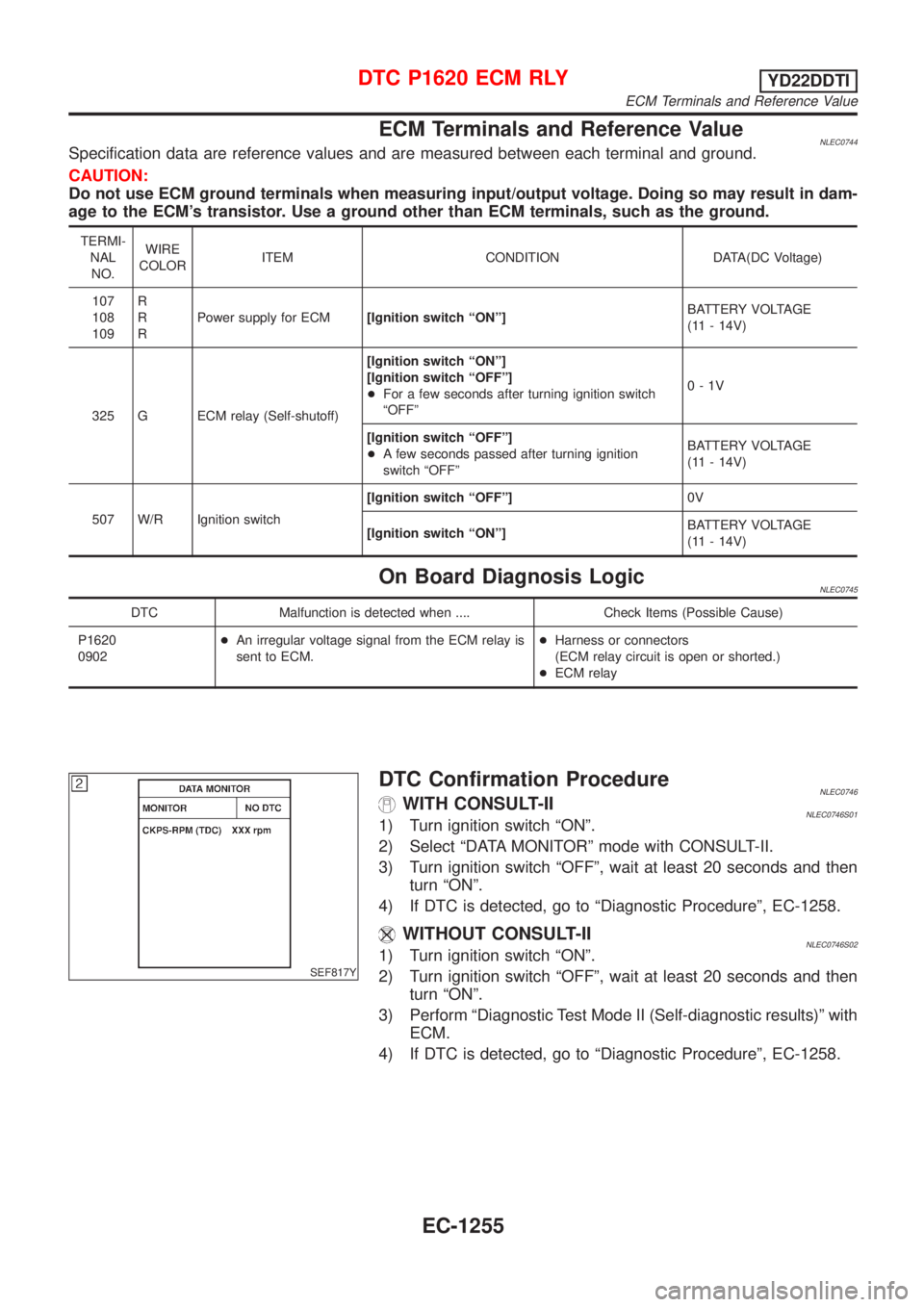
ECM Terminals and Reference ValueNLEC0744Specification data are reference values and are measured between each terminal and ground.
CAUTION:
Do not use ECM ground terminals when measuring input/output voltage. Doing so may result in dam-
age to the ECM's transistor. Use a ground other than ECM terminals, such as the ground.
TERMI-
NAL
NO.WIRE
COLORITEM CONDITION DATA(DC Voltage)
107
108
109R
R
RPower supply for ECM[Ignition switch ªONº]BATTERY VOLTAGE
(11 - 14V)
325 G ECM relay (Self-shutoff)[Ignition switch ªONº]
[Ignition switch ªOFFº]
+For a few seconds after turning ignition switch
ªOFFº0-1V
[Ignition switch ªOFFº]
+A few seconds passed after turning ignition
switch ªOFFºBATTERY VOLTAGE
(11 - 14V)
507 W/R Ignition switch[Ignition switch ªOFFº]0V
[Ignition switch ªONº]BATTERY VOLTAGE
(11 - 14V)
On Board Diagnosis LogicNLEC0745
DTC Malfunction is detected when .... Check Items (Possible Cause)
P1620
0902+An irregular voltage signal from the ECM relay is
sent to ECM.+Harness or connectors
(ECM relay circuit is open or shorted.)
+ECM relay
SEF817Y
DTC Confirmation ProcedureNLEC0746WITH CONSULT-IINLEC0746S011) Turn ignition switch ªONº.
2) Select ªDATA MONITORº mode with CONSULT-II.
3) Turn ignition switch ªOFFº, wait at least 20 seconds and then
turn ªONº.
4) If DTC is detected, go to ªDiagnostic Procedureº, EC-1258.
WITHOUT CONSULT-IINLEC0746S021) Turn ignition switch ªONº.
2) Turn ignition switch ªOFFº, wait at least 20 seconds and then
turn ªONº.
3) Perform ªDiagnostic Test Mode II (Self-diagnostic results)º with
ECM.
4) If DTC is detected, go to ªDiagnostic Procedureº, EC-1258.
DTC P1620 ECM RLYYD22DDTI
ECM Terminals and Reference Value
EC-1255