NISSAN ALMERA TINO 2001 Service Repair Manual
ALMERA TINO 2001
NISSAN
NISSAN
https://www.carmanualsonline.info/img/5/57352/w960_57352-0.png
NISSAN ALMERA TINO 2001 Service Repair Manual
Trending: power steering, OBD port, oil filter, service reset, parking sensors, fuel tank removal, fuse box
Page 2001 of 3051
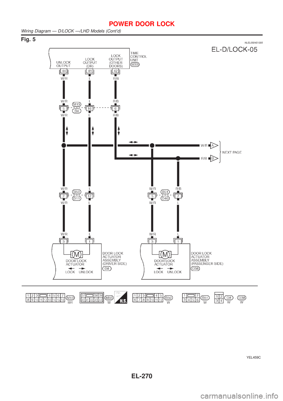
Fig. 5NLEL0504S1305
YEL459C
POWER DOOR LOCK
Wiring Diagram Ð D/LOCK Ð/LHD Models (Cont'd)
EL-270
Page 2002 of 3051
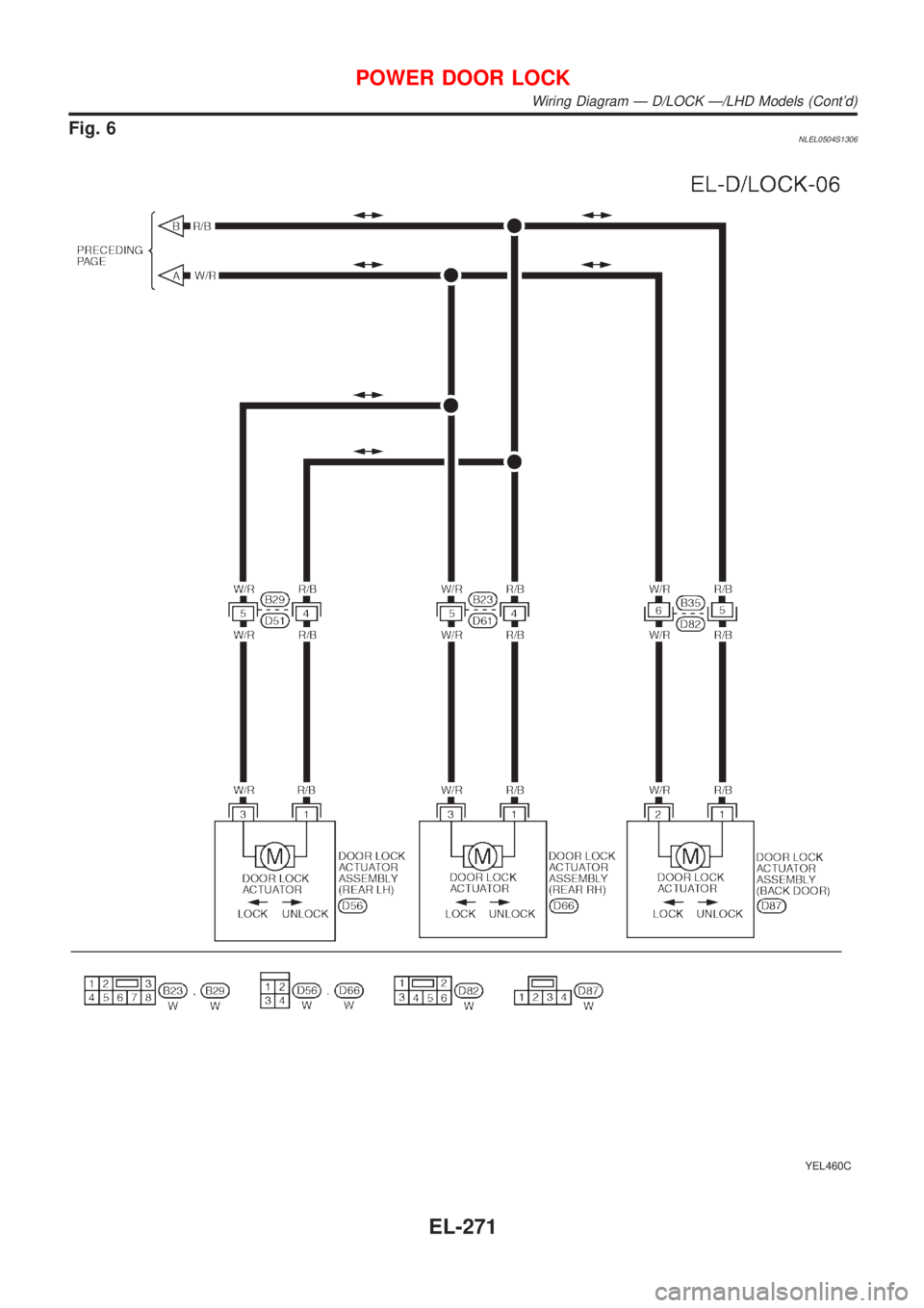
Fig. 6NLEL0504S1306
YEL460C
POWER DOOR LOCK
Wiring Diagram Ð D/LOCK Ð/LHD Models (Cont'd)
EL-271
Page 2003 of 3051
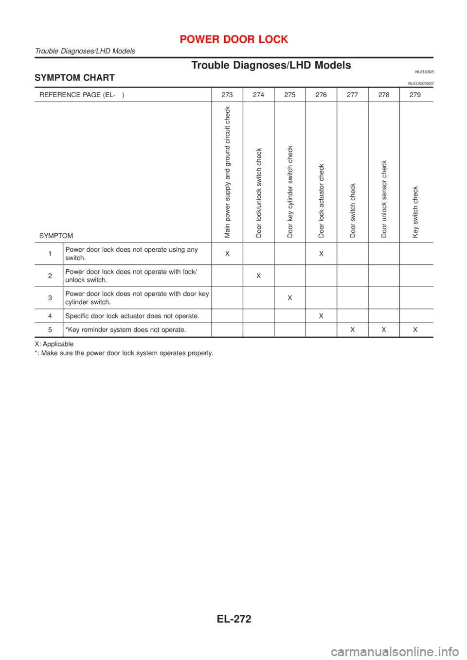
Trouble Diagnoses/LHD ModelsNLEL0505SYMPTOM CHARTNLEL0505S02
REFERENCE PAGE (EL- ) 273 274 275 276 277 278 279
SYMPTOM
Main power supply and ground circuit check
Door lock/unlock switch check
Door key cylinder switch check
Door lock actuator check
Door switch check
Door unlock sensor check
Key switch check
1Power door lock does not operate using any
switch.XX
2Power door lock does not operate with lock/
unlock switch.X
3Power door lock does not operate with door key
cylinder switch.X
4 Specific door lock actuator does not operate. X
5 *Key reminder system does not operate. X X X
X: Applicable
*: Make sure the power door lock system operates properly.
POWER DOOR LOCK
Trouble Diagnoses/LHD Models
EL-272
Page 2004 of 3051
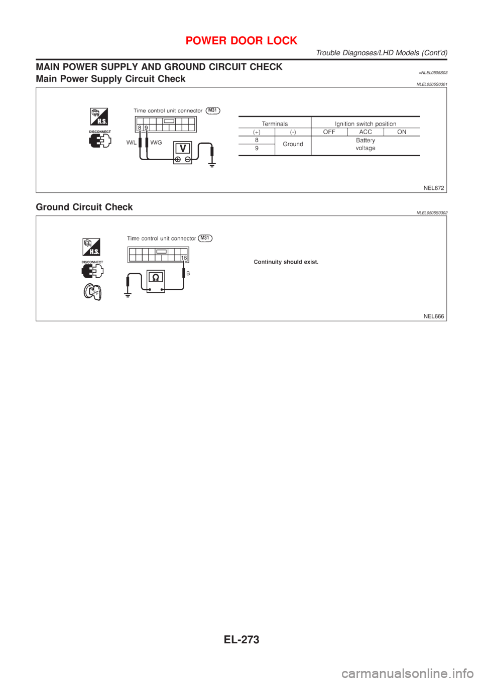
MAIN POWER SUPPLY AND GROUND CIRCUIT CHECK=NLEL0505S03Main Power Supply Circuit CheckNLEL0505S0301
NEL672
Ground Circuit CheckNLEL0505S0302
NEL666
POWER DOOR LOCK
Trouble Diagnoses/LHD Models (Cont'd)
EL-273
Page 2005 of 3051
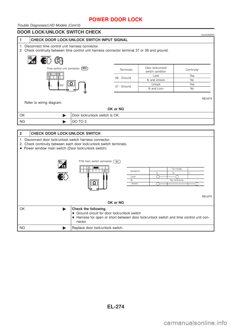
DOOR LOCK/UNLOCK SWITCH CHECK=NLEL0505S04
1 CHECK DOOR LOCK/UNLOCK SWITCH INPUT SIGNAL
1. Disconnect time control unit harness connector.
2. Check continuity between time control unit harness connector terminal 37 or 38 and ground.
NEL674
Refer to wiring diagram.
OK or NG
OK©Door lock/unlock switch is OK.
NG©GO TO 2.
2 CHECK DOOR LOCK/UNLOCK SWITCH
1. Disconnect door lock/unlock switch harness connector.
2. Check continuity between each door lock/unlock switch terminals.
+Power window main switch (Door lock/unlock switch)
NEL675
OK or NG
OK©Check the following.
+Ground circuit for door lock/unlock switch
+Harness for open or short between door lock/unlock switch and time control unit con-
nector
NG©Replace door lock/unlock switch.
POWER DOOR LOCK
Trouble Diagnoses/LHD Models (Cont'd)
EL-274
Page 2006 of 3051
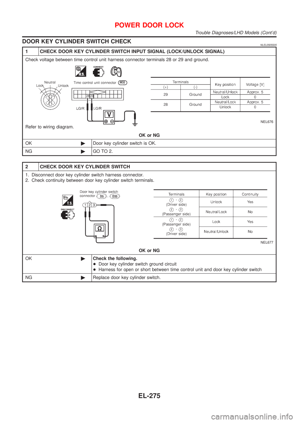
DOOR KEY CYLINDER SWITCH CHECKNLEL0505S05
1 CHECK DOOR KEY CYLINDER SWITCH INPUT SIGNAL (LOCK/UNLOCK SIGNAL)
Check voltage between time control unit harness connector terminals 28 or 29 and ground.
NEL676
Refer to wiring diagram.
OK or NG
OK©Door key cylinder switch is OK.
NG©GO TO 2.
2 CHECK DOOR KEY CYLINDER SWITCH
1. Disconnect door key cylinder switch harness connector.
2. Check continuity between door key cylinder switch terminals.
NEL677
OK or NG
OK©Check the following.
+Door key cylinder switch ground circuit
+Harness for open or short between time control unit and door key cylinder switch
NG©Replace door key cylinder switch.
POWER DOOR LOCK
Trouble Diagnoses/LHD Models (Cont'd)
EL-275
Page 2007 of 3051
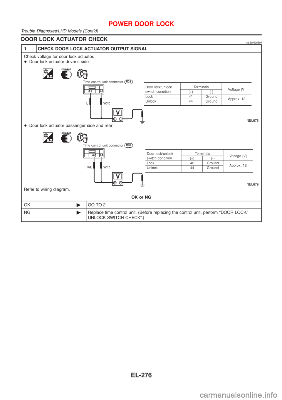
DOOR LOCK ACTUATOR CHECKNLEL0505S06
1 CHECK DOOR LOCK ACTUATOR OUTPUT SIGNAL
Check voltage for door lock actuator.
+Door lock actuator driver's side
NEL678
+Door lock actuator passenger side and rear
NEL679
Refer to wiring diagram.
OK or NG
OK©GO TO 2.
NG©Replace time control unit. (Before replacing the control unit, perform ªDOOR LOCK/
UNLOCK SWITCH CHECKº.)
POWER DOOR LOCK
Trouble Diagnoses/LHD Models (Cont'd)
EL-276
Page 2008 of 3051
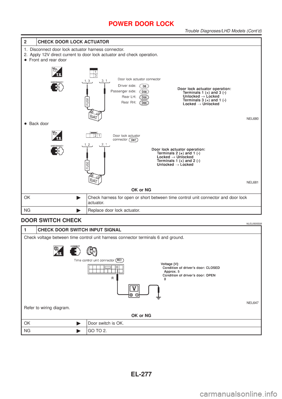
2 CHECK DOOR LOCK ACTUATOR
1. Disconnect door lock actuator harness connector.
2. Apply 12V direct current to door lock actuator and check operation.
+Front and rear door
NEL680
+Back door
NEL681
OK or NG
OK©Check harness for open or short between time control unit connector and door lock
actuator.
NG©Replace door lock actuator.
DOOR SWITCH CHECKNLEL0505S08
1 CHECK DOOR SWITCH INPUT SIGNAL
Check voltage between time control unit harness connector terminals 6 and ground.
NEL647
Refer to wiring diagram.
OK or NG
OK©Door switch is OK.
NG©GO TO 2.
POWER DOOR LOCK
Trouble Diagnoses/LHD Models (Cont'd)
EL-277
Page 2009 of 3051
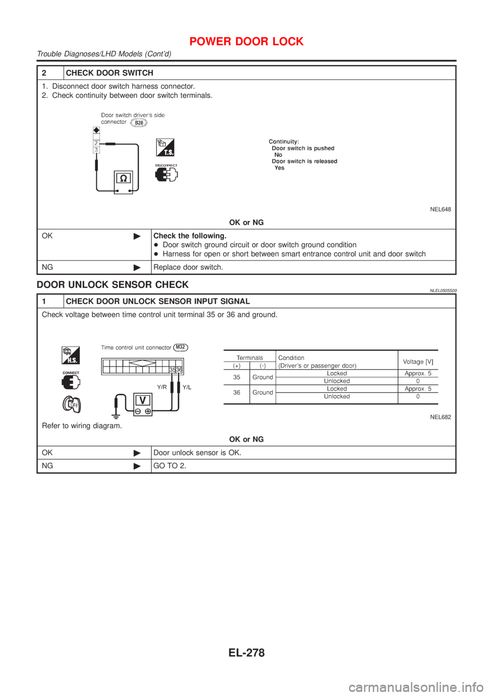
2 CHECK DOOR SWITCH
1. Disconnect door switch harness connector.
2. Check continuity between door switch terminals.
NEL648
OK or NG
OK©Check the following.
+Door switch ground circuit or door switch ground condition
+Harness for open or short between smart entrance control unit and door switch
NG©Replace door switch.
DOOR UNLOCK SENSOR CHECKNLEL0505S09
1 CHECK DOOR UNLOCK SENSOR INPUT SIGNAL
Check voltage between time control unit terminal 35 or 36 and ground.
NEL682
Refer to wiring diagram.
OK or NG
OK©Door unlock sensor is OK.
NG©GO TO 2.
POWER DOOR LOCK
Trouble Diagnoses/LHD Models (Cont'd)
EL-278
Page 2010 of 3051
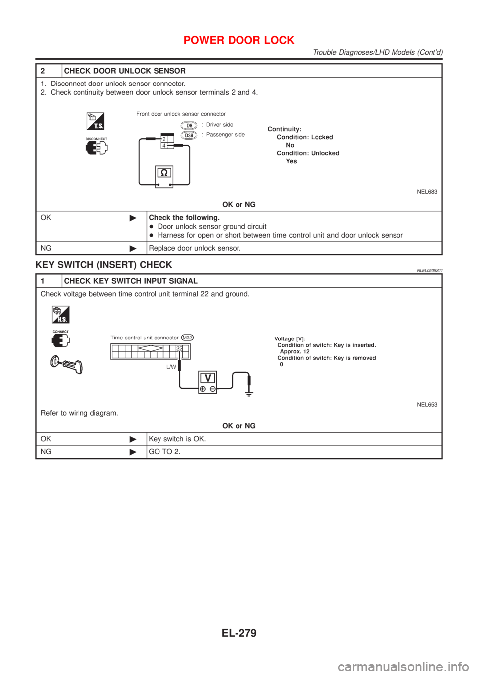
2 CHECK DOOR UNLOCK SENSOR
1. Disconnect door unlock sensor connector.
2. Check continuity between door unlock sensor terminals 2 and 4.
NEL683
OK or NG
OK©Check the following.
+Door unlock sensor ground circuit
+Harness for open or short between time control unit and door unlock sensor
NG©Replace door unlock sensor.
KEY SWITCH (INSERT) CHECKNLEL0505S11
1 CHECK KEY SWITCH INPUT SIGNAL
Check voltage between time control unit terminal 22 and ground.
NEL653
Refer to wiring diagram.
OK or NG
OK©Key switch is OK.
NG©GO TO 2.
POWER DOOR LOCK
Trouble Diagnoses/LHD Models (Cont'd)
EL-279
Trending: jump start terminals, BT 10, set clock, fuel filter, washer fluid, checking oil, fuse diagram
