NISSAN ALMERA TINO 2001 Service Repair Manual
Manufacturer: NISSAN, Model Year: 2001, Model line: ALMERA TINO, Model: NISSAN ALMERA TINO 2001Pages: 3051, PDF Size: 46.38 MB
Page 261 of 3051
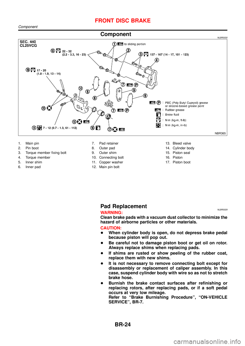
ComponentNLBR0030
NBR365
1. Main pin
2. Pin boot
3. Torque member fixing bolt
4. Torque member
5. Inner shim
6. Inner pad7. Pad retainer
8. Outer pad
9. Outer shim
10. Connecting bolt
11. Copper washer
12. Main pin bolt13. Bleed valve
14. Cylinder body
15. Piston seal
16. Piston
17. Piston boot
Pad ReplacementNLBR0029WARNING:
Clean brake pads with a vacuum dust collector to minimize the
hazard of airborne particles or other materials.
CAUTION:
+When cylinder body is open, do not depress brake pedal
because piston will pop out.
+Be careful not to damage piston boot or get oil on rotor.
Always replace shims when replacing pads.
+If shims are rusted or show peeling of the rubber coat,
replace them with new shims.
+It is not necessary to remove connecting bolt except for
disassembly or replacement of caliper assembly. In this
case, suspend cylinder body with wire so as not to stretch
brake hose.
+Burnish the brake contact surfaces after refinishing or
replacing rotors, after replacing pads, or if a soft pedal
occurs at very low mileage.
Refer to“Brake Burnishing Procedure”,“ON-VEHICLE
SERVICE”, BR-7.
FRONT DISC BRAKE
Component
BR-24
Page 262 of 3051
SBR976B
SBR932C
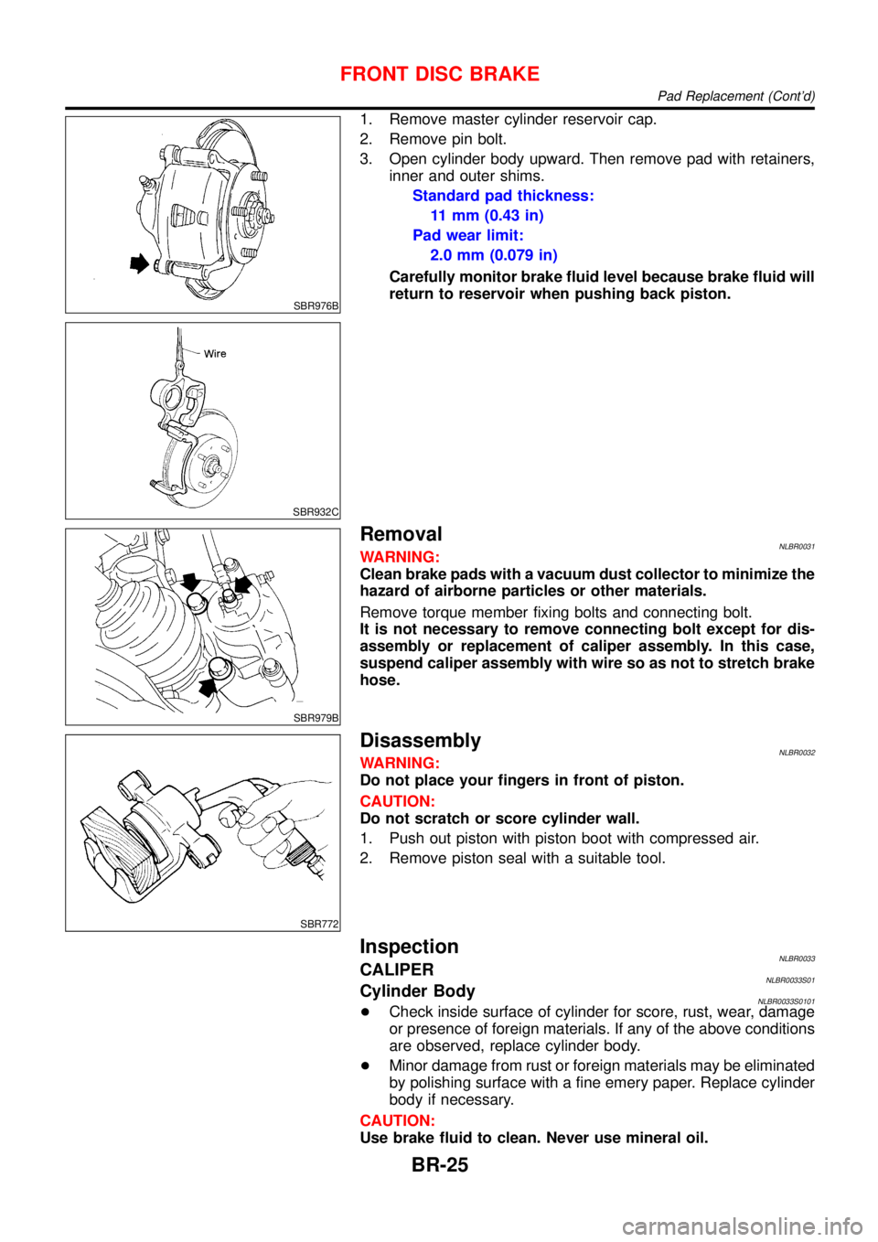
1. Remove master cylinder reservoir cap.
2. Remove pin bolt.
3. Open cylinder body upward. Then remove pad with retainers,
inner and outer shims.
Standard pad thickness:
11 mm (0.43 in)
Pad wear limit:
2.0 mm (0.079 in)
Carefully monitor brake fluid level because brake fluid will
return to reservoir when pushing back piston.
SBR979B
RemovalNLBR0031WARNING:
Clean brake pads with a vacuum dust collector to minimize the
hazard of airborne particles or other materials.
Remove torque member fixing bolts and connecting bolt.
It is not necessary to remove connecting bolt except for dis-
assembly or replacement of caliper assembly. In this case,
suspend caliper assembly with wire so as not to stretch brake
hose.
SBR772
DisassemblyNLBR0032WARNING:
Do not place your fingers in front of piston.
CAUTION:
Do not scratch or score cylinder wall.
1. Push out piston with piston boot with compressed air.
2. Remove piston seal with a suitable tool.
InspectionNLBR0033CALIPERNLBR0033S01Cylinder BodyNLBR0033S0101+Check inside surface of cylinder for score, rust, wear, damage
or presence of foreign materials. If any of the above conditions
are observed, replace cylinder body.
+Minor damage from rust or foreign materials may be eliminated
by polishing surface with a fine emery paper. Replace cylinder
body if necessary.
CAUTION:
Use brake fluid to clean. Never use mineral oil.
FRONT DISC BRAKE
Pad Replacement (Cont’d)
BR-25
Page 263 of 3051
PistonNLBR0033S0102CAUTION:
Piston sliding surface is plated. Do not polish with emery
paper even if rust or foreign materials are stuck to sliding
surface.
Check piston for score, rust, wear, damage or presence of foreign
materials. Replace if any of the above conditions are observed.
Slide Pin, Pin Bolt and Pin BootNLBR0033S0103Check for wear, cracks or other damage. Replace if any of the
above conditions are observed.
ROTORNLBR0033S02Rubbing SurfaceNLBR0033S0201Check rotor for roughness, cracks or chips.
SBR219C
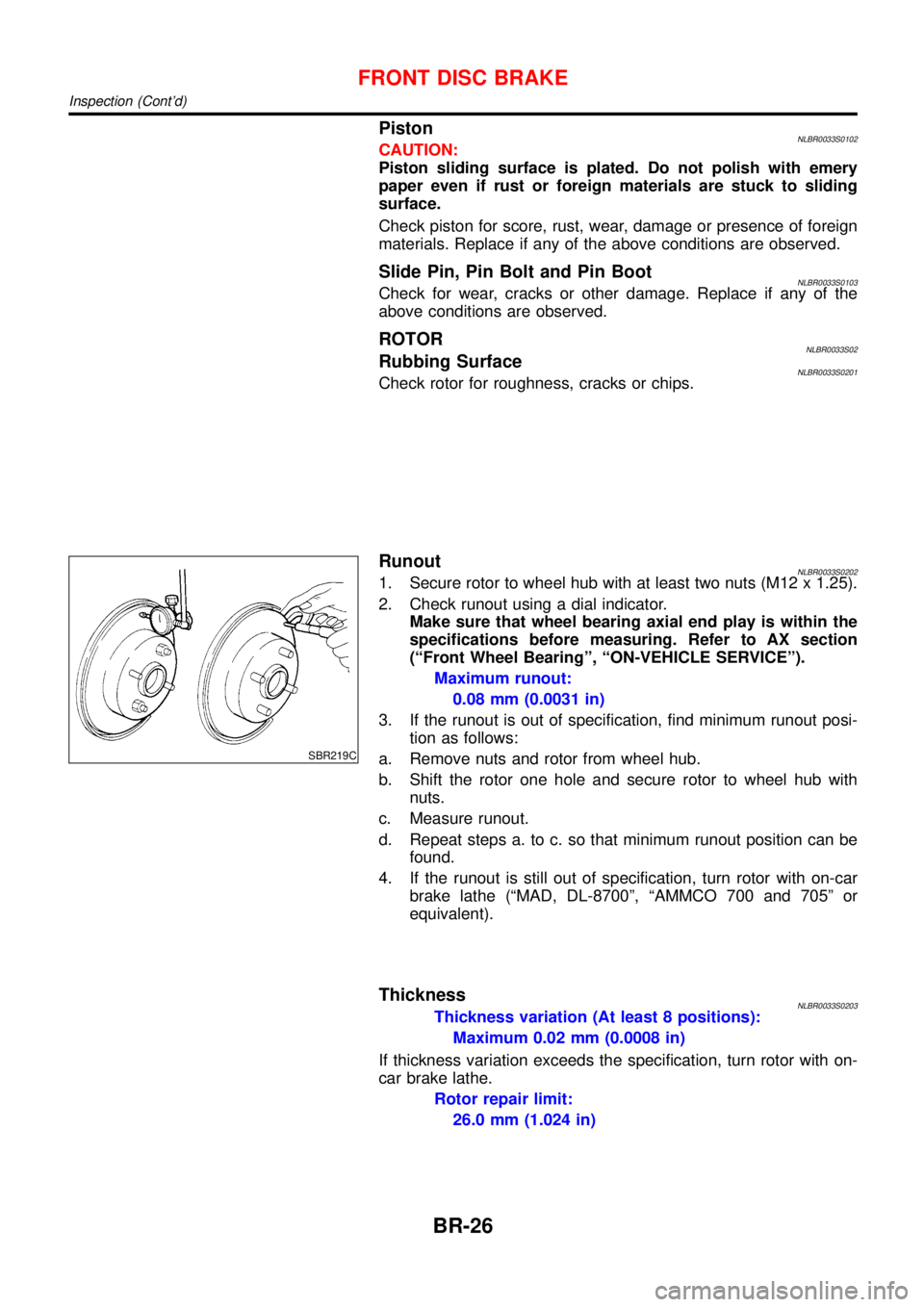
RunoutNLBR0033S02021. Secure rotor to wheel hub with at least two nuts (M12 x 1.25).
2. Check runout using a dial indicator.
Make sure that wheel bearing axial end play is within the
specifications before measuring. Refer to AX section
(“Front Wheel Bearing”,“ON-VEHICLE SERVICE”).
Maximum runout:
0.08 mm (0.0031 in)
3. If the runout is out of specification, find minimum runout posi-
tion as follows:
a. Remove nuts and rotor from wheel hub.
b. Shift the rotor one hole and secure rotor to wheel hub with
nuts.
c. Measure runout.
d. Repeat steps a. to c. so that minimum runout position can be
found.
4. If the runout is still out of specification, turn rotor with on-car
brake lathe (“MAD, DL-8700”,“AMMCO 700 and 705”or
equivalent).
ThicknessNLBR0033S0203Thickness variation (At least 8 positions):
Maximum 0.02 mm (0.0008 in)
If thickness variation exceeds the specification, turn rotor with on-
car brake lathe.
Rotor repair limit:
26.0 mm (1.024 in)
FRONT DISC BRAKE
Inspection (Cont’d)
BR-26
Page 264 of 3051
SBR574
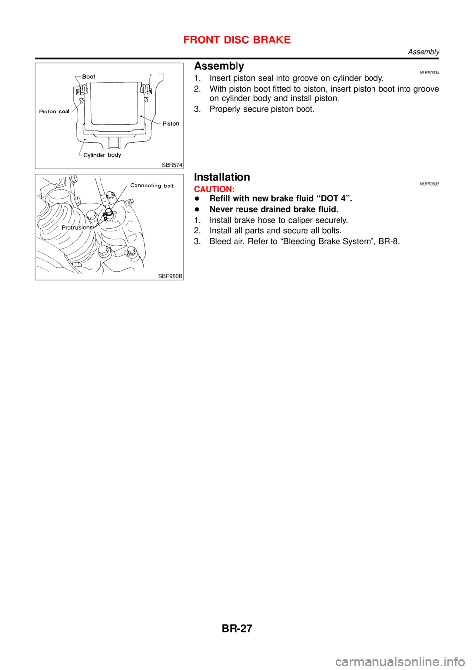
AssemblyNLBR00341. Insert piston seal into groove on cylinder body.
2. With piston boot fitted to piston, insert piston boot into groove
on cylinder body and install piston.
3. Properly secure piston boot.
SBR980B
InstallationNLBR0035CAUTION:
+Refill with new brake fluid“DOT 4”.
+Never reuse drained brake fluid.
1. Install brake hose to caliper securely.
2. Install all parts and secure all bolts.
3. Bleed air. Refer to“Bleeding Brake System”, BR-8.
FRONT DISC BRAKE
Assembly
BR-27
Page 265 of 3051
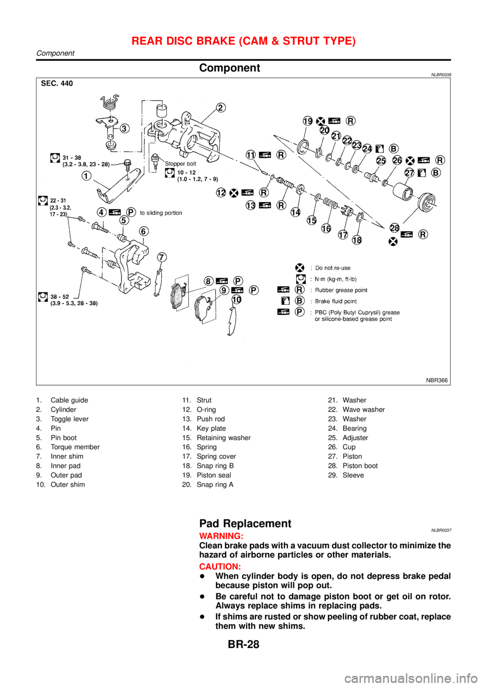
ComponentNLBR0038
NBR366
1. Cable guide
2. Cylinder
3. Toggle lever
4. Pin
5. Pin boot
6. Torque member
7. Inner shim
8. Inner pad
9. Outer pad
10. Outer shim11. Strut
12. O-ring
13. Push rod
14. Key plate
15. Retaining washer
16. Spring
17. Spring cover
18. Snap ring B
19. Piston seal
20. Snap ring A21. Washer
22. Wave washer
23. Washer
24. Bearing
25. Adjuster
26. Cup
27. Piston
28. Piston boot
29. Sleeve
Pad ReplacementNLBR0037WARNING:
Clean brake pads with a vacuum dust collector to minimize the
hazard of airborne particles or other materials.
CAUTION:
+When cylinder body is open, do not depress brake pedal
because piston will pop out.
+Be careful not to damage piston boot or get oil on rotor.
Always replace shims in replacing pads.
+If shims are rusted or show peeling of rubber coat, replace
them with new shims.
REAR DISC BRAKE (CAM & STRUT TYPE)
Component
BR-28
Page 266 of 3051
+It is not necessary to remove connecting bolt except for
disassembly or replacement of caliper assembly. In this
case, suspend cylinder body with wire so as not to stretch
brake hose.
+Burnish the brake contact surfaces after refinishing or
replacing rotors, after replacing pads, or if a soft pedal
occurs at very low mileage.
Refer to“Brake Burnishing Procedure”,“ON-VEHICLE
SERVICE”, BR-7.
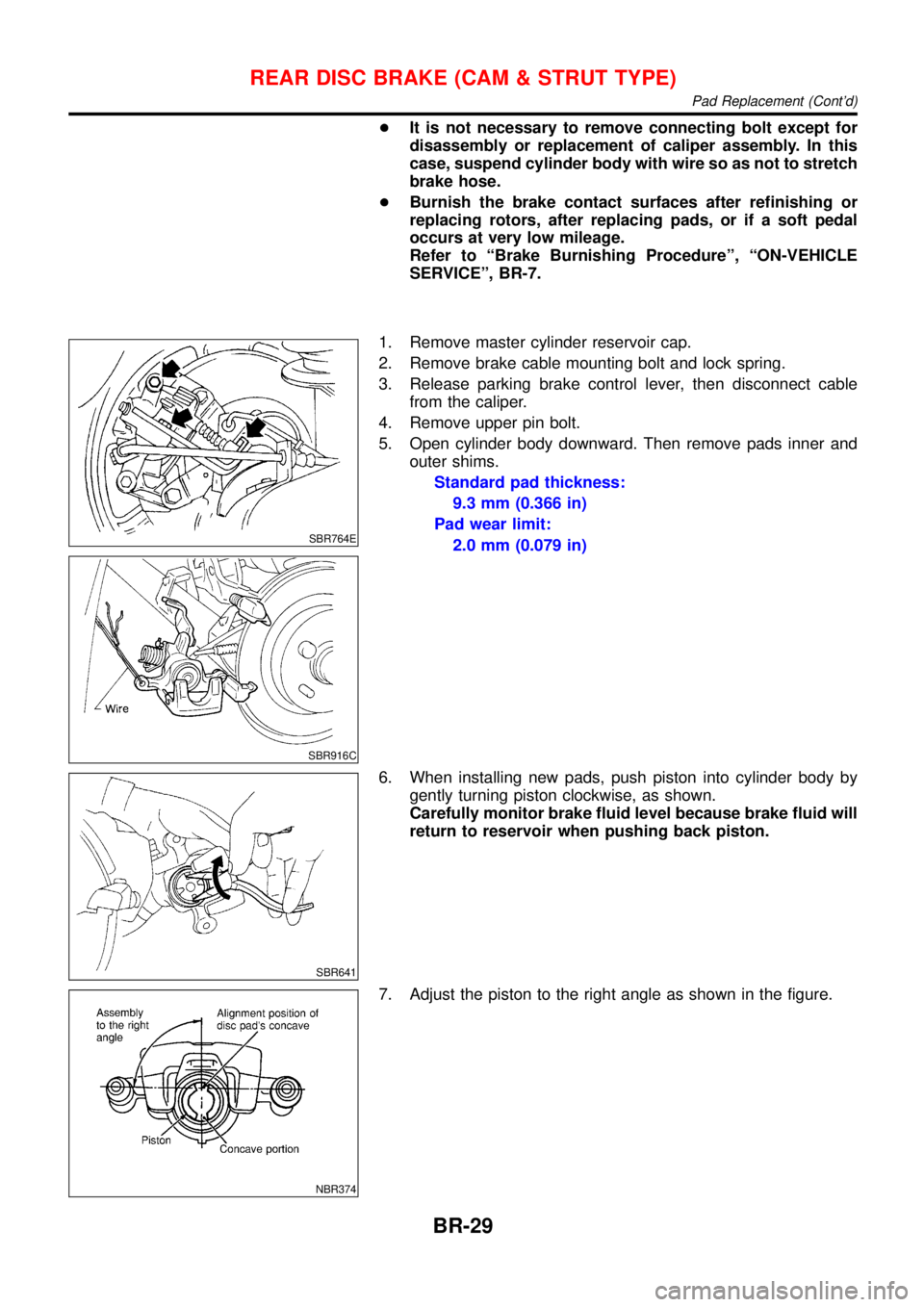
SBR764E
SBR916C
1. Remove master cylinder reservoir cap.
2. Remove brake cable mounting bolt and lock spring.
3. Release parking brake control lever, then disconnect cable
from the caliper.
4. Remove upper pin bolt.
5. Open cylinder body downward. Then remove pads inner and
outer shims.
Standard pad thickness:
9.3 mm (0.366 in)
Pad wear limit:
2.0 mm (0.079 in)
SBR641
6. When installing new pads, push piston into cylinder body by
gently turning piston clockwise, as shown.
Carefully monitor brake fluid level because brake fluid will
return to reservoir when pushing back piston.
NBR374
7. Adjust the piston to the right angle as shown in the figure.
REAR DISC BRAKE (CAM & STRUT TYPE)
Pad Replacement (Cont’d)
BR-29
Page 267 of 3051
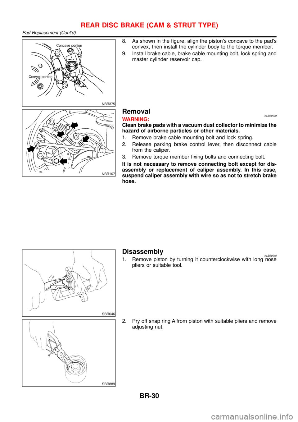
NBR375
8. As shown in the figure, align the piston’s concave to the pad’s
convex, then install the cylinder body to the torque member.
9. Install brake cable, brake cable mounting bolt, lock spring and
master cylinder reservoir cap.
NBR167
RemovalNLBR0039WARNING:
Clean brake pads with a vacuum dust collector to minimize the
hazard of airborne particles or other materials.
1. Remove brake cable mounting bolt and lock spring.
2. Release parking brake control lever, then disconnect cable
from the caliper.
3. Remove torque member fixing bolts and connecting bolt.
It is not necessary to remove connecting bolt except for dis-
assembly or replacement of caliper assembly. In this case,
suspend caliper assembly with wire so as not to stretch brake
hose.
SBR646
DisassemblyNLBR00401. Remove piston by turning it counterclockwise with long nose
pliers or suitable tool.
SBR889
2. Pry off snap ring A from piston with suitable pliers and remove
adjusting nut.
REAR DISC BRAKE (CAM & STRUT TYPE)
Pad Replacement (Cont’d)
BR-30
Page 268 of 3051
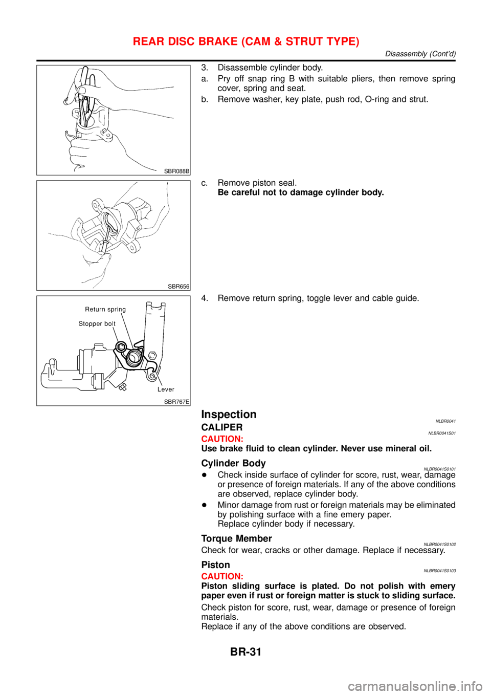
SBR088B
3. Disassemble cylinder body.
a. Pry off snap ring B with suitable pliers, then remove spring
cover, spring and seat.
b. Remove washer, key plate, push rod, O-ring and strut.
SBR656
c. Remove piston seal.
Be careful not to damage cylinder body.
SBR767E
4. Remove return spring, toggle lever and cable guide.
InspectionNLBR0041CALIPERNLBR0041S01CAUTION:
Use brake fluid to clean cylinder. Never use mineral oil.
Cylinder BodyNLBR0041S0101+Check inside surface of cylinder for score, rust, wear, damage
or presence of foreign materials. If any of the above conditions
are observed, replace cylinder body.
+Minor damage from rust or foreign materials may be eliminated
by polishing surface with a fine emery paper.
Replace cylinder body if necessary.
Torque MemberNLBR0041S0102Check for wear, cracks or other damage. Replace if necessary.
PistonNLBR0041S0103CAUTION:
Piston sliding surface is plated. Do not polish with emery
paper even if rust or foreign matter is stuck to sliding surface.
Check piston for score, rust, wear, damage or presence of foreign
materials.
Replace if any of the above conditions are observed.
REAR DISC BRAKE (CAM & STRUT TYPE)
Disassembly (Cont’d)
BR-31
Page 269 of 3051
Pin and Pin BootNLBR0041S0104Check for wear, cracks or other damage.
Replace if any of the above conditions are observed.
SBR219C
ROTORNLBR0041S02Rubbing SurfaceNLBR0041S0201Check rotor for roughness, cracks or chips.
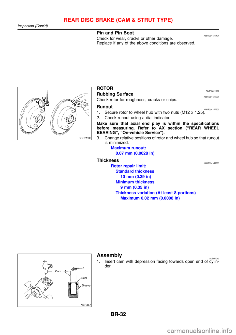
RunoutNLBR0041S02021. Secure rotor to wheel hub with two nuts (M12 x 1.25).
2. Check runout using a dial indicator.
Make sure that axial end play is within the specifications
before measuring. Refer to AX section (“REAR WHEEL
BEARING”,“On-vehicle Service”).
3. Change relative positions of rotor and wheel hub so that runout
is minimized.
Maximum runout:
0.07 mm (0.0028 in)
ThicknessNLBR0041S0203Rotor repair limit:
Standard thickness
10 mm (0.39 in)
Minimum thickness
9 mm (0.35 in)
Thickness variation (At least 8 portions)
Maximum 0.02 mm (0.0008 in)
NBR367
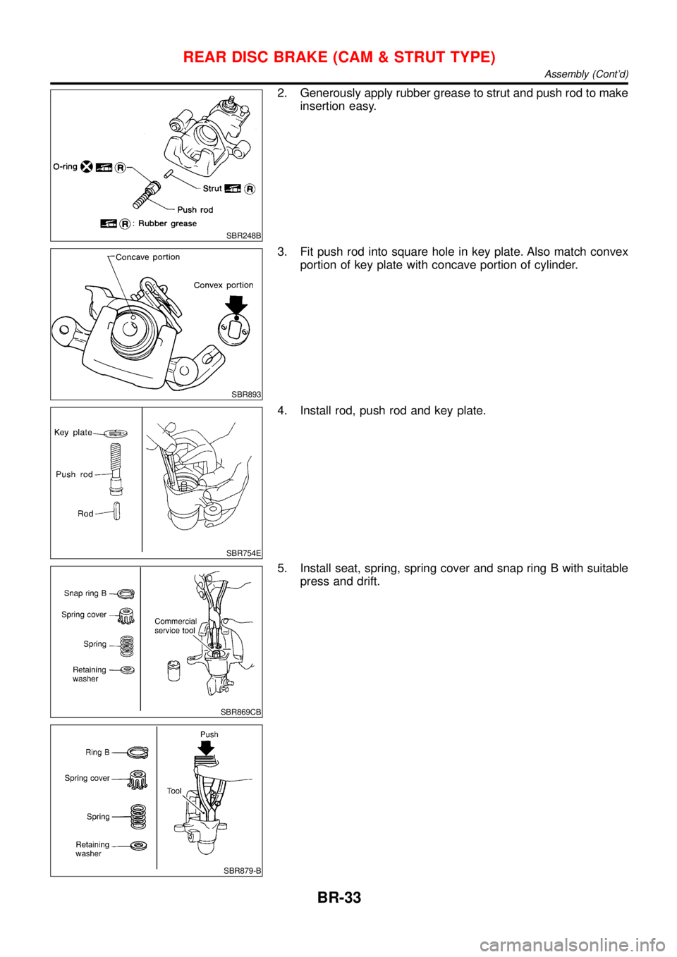
AssemblyNLBR00421. Insert cam with depression facing towards open end of cylin-
der.
REAR DISC BRAKE (CAM & STRUT TYPE)
Inspection (Cont’d)
BR-32
Page 270 of 3051
SBR248B
2. Generously apply rubber grease to strut and push rod to make
insertion easy.
SBR893
3. Fit push rod into square hole in key plate. Also match convex
portion of key plate with concave portion of cylinder.
SBR754E
4. Install rod, push rod and key plate.
SBR869CB
SBR879-B
5. Install seat, spring, spring cover and snap ring B with suitable
press and drift.
REAR DISC BRAKE (CAM & STRUT TYPE)
Assembly (Cont’d)
BR-33