NISSAN ALMERA TINO 2001 Service Repair Manual
Manufacturer: NISSAN, Model Year: 2001, Model line: ALMERA TINO, Model: NISSAN ALMERA TINO 2001Pages: 3051, PDF Size: 46.38 MB
Page 251 of 3051

NBR353
3. Remove the circlip with suitable pliers while piston is pushed
into cylinder.
SBR232E
4. Remove piston stopper pin while piston is pushed into cylinder.
5. Remove piston assemblies.
If it is difficult to remove secondary piston assembly,
gradually apply compressed air through fluid outlet.
InspectionNLBR0119Check for the following items.
Replace any part if damaged.
Master cylinder:
+Pin holes or scratches on inner wall.
Piston:
+Deformation or scratches on piston cups.
SBR233E
AssemblyNLBR01201. Insert secondary piston assembly. Then insert primary piston
assembly.
+Pay attention to alignment of secondary piston slit with
valve stopper mounting hole of cylinder body.
SBR232E
2. Install piston stopper pin while piston is pushed into cylinder.
Then secure the primary and secondary piston assemblies
with new circlip.
3. Insert washer and push reservoir seals and adapter into cylin-
der body.
4. Install elastic pin.
MASTER CYLINDER
Disassembly (Cont’d)
BR-14
Page 252 of 3051
InstallationNLBR0121CAUTION:
+Refill with new brake fluid“DOT 4”.
+Never reuse drained brake fluid.
1. Place master cylinder onto brake booster and secure mount-
ing nuts lightly.
2. Torque mounting nuts.
:13-15N·m (1.3 - 1.5 kg-m,9-11ft-lb)
NBR363
NBR364
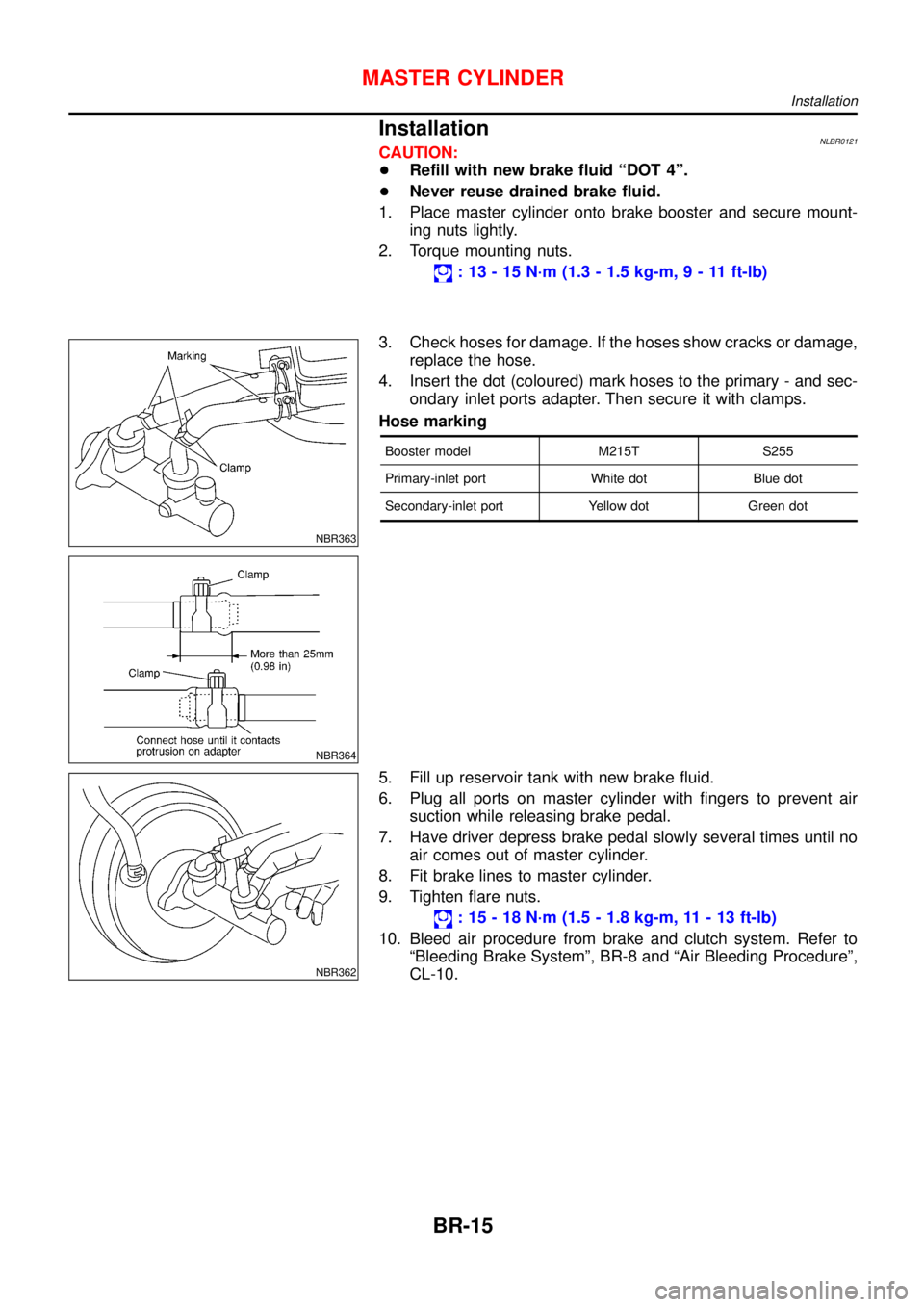
3. Check hoses for damage. If the hoses show cracks or damage,
replace the hose.
4. Insert the dot (coloured) mark hoses to the primary - and sec-
ondary inlet ports adapter. Then secure it with clamps.
Hose marking
Booster model M215T S255
Primary-inlet port White dot Blue dot
Secondary-inlet port Yellow dot Green dot
NBR362
5. Fill up reservoir tank with new brake fluid.
6. Plug all ports on master cylinder with fingers to prevent air
suction while releasing brake pedal.
7. Have driver depress brake pedal slowly several times until no
air comes out of master cylinder.
8. Fit brake lines to master cylinder.
9. Tighten flare nuts.
:15-18N·m (1.5 - 1.8 kg-m, 11 - 13 ft-lb)
10. Bleed air procedure from brake and clutch system. Refer to
“Bleeding Brake System”, BR-8 and“Air Bleeding Procedure”,
CL-10.
MASTER CYLINDER
Installation
BR-15
Page 253 of 3051
SBR002A
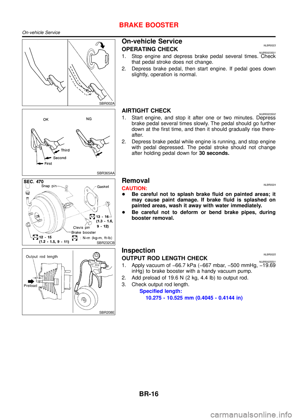
On-vehicle ServiceNLBR0023OPERATING CHECKNLBR0023S011. Stop engine and depress brake pedal several times. Check
that pedal stroke does not change.
2. Depress brake pedal, then start engine. If pedal goes down
slightly, operation is normal.
SBR365AA
AIRTIGHT CHECKNLBR0023S021. Start engine, and stop it after one or two minutes. Depress
brake pedal several times slowly. The pedal should go further
down at the first time, and then it should gradually rise there-
after.
2. Depress brake pedal while engine is running, and stop engine
with pedal depressed. The pedal stroke should not change
after holding pedal down for30 seconds.
SBR232CB
RemovalNLBR0024CAUTION:
+Be careful not to splash brake fluid on painted areas; it
may cause paint damage. If brake fluid is splashed on
painted areas, wash it away with water immediately.
+Be careful not to deform or bend brake pipes, during
booster removal.
SBR208E
InspectionNLBR0025OUTPUT ROD LENGTH CHECKNLBR0025S011. Apply vacuum of �66.7 kPa (�667 mbar, �500 mmHg, �19.69
inHg) to brake booster with a handy vacuum pump.
2. Add preload of 19.6 N (2 kg, 4.4 lb) to output rod.
3. Check output rod length.
Specified length:
10.275 - 10.525 mm (0.4045 - 0.4144 in)
BRAKE BOOSTER
On-vehicle Service
BR-16
Page 254 of 3051
InstallationNLBR0026CAUTION:
+Be careful not to deform or bend brake pipes, during
booster installation.
+Replace clevis pin if damaged.
+Refill with new brake fluid“DOT 4”.
+Never reuse drained brake fluid.
+Take care not to damage brake booster mounting bolt
thread during installation. Due to the acute angle of
installation, the threads can be damaged with the dash
panel.
SBR237EA
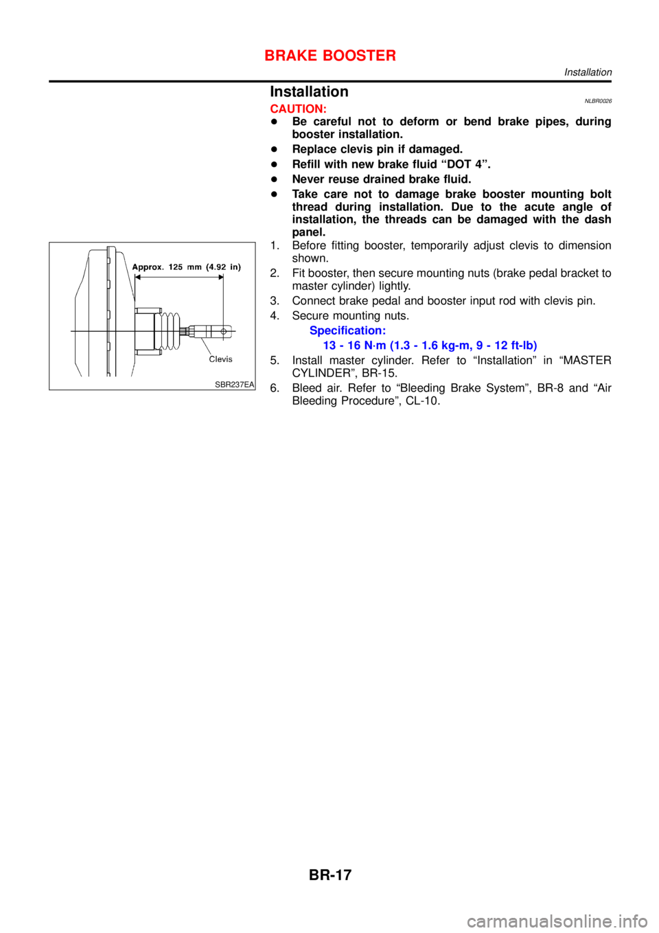
1. Before fitting booster, temporarily adjust clevis to dimension
shown.
2. Fit booster, then secure mounting nuts (brake pedal bracket to
master cylinder) lightly.
3. Connect brake pedal and booster input rod with clevis pin.
4. Secure mounting nuts.
Specification:
13-16N·m (1.3 - 1.6 kg-m,9-12ft-lb)
5. Install master cylinder. Refer to“Installation”in“MASTER
CYLINDER”, BR-15.
6. Bleed air. Refer to“Bleeding Brake System”, BR-8 and“Air
Bleeding Procedure”, CL-10.
BRAKE BOOSTER
Installation
BR-17
Page 255 of 3051
SBR225B
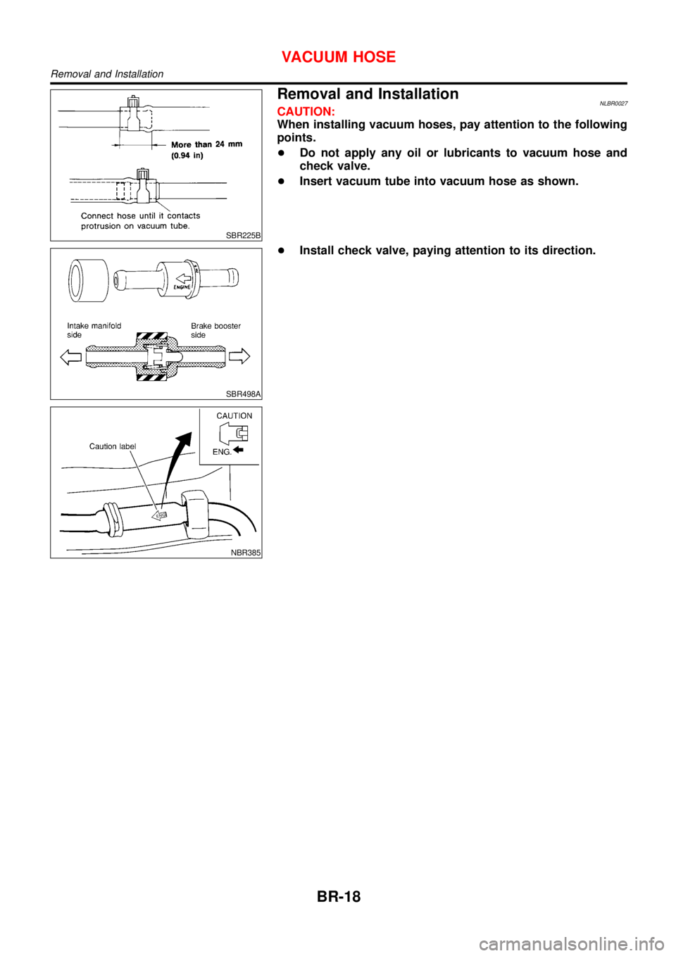
Removal and InstallationNLBR0027CAUTION:
When installing vacuum hoses, pay attention to the following
points.
+Do not apply any oil or lubricants to vacuum hose and
check valve.
+Insert vacuum tube into vacuum hose as shown.
SBR498A
NBR385
+Install check valve, paying attention to its direction.
VACUUM HOSE
Removal and Installation
BR-18
Page 256 of 3051

Inspection=NLBR0028HOSES AND CONNECTORSNLBR0028S01Check vacuum lines, connections and check valve for airtightness,
improper attachment chafing and deterioration.
SBR844B
CHECK VALVENLBR0028S02Check vacuum with a vacuum pump.
Connect to booster side Vacuum should exist.
Connect to engine side Vacuum should not exist.
SBR943A
VACUUM HOSE
Inspection
BR-19
Page 257 of 3051

RemovalNLBR0123
SBR631E
1. Remove parts shown below.
+Air duct, air cleaner case (upper)
+Engine cover
+Rocker cover
+Exhaust manifold cover
+EGR tube
2. Disconnect vacuum hose from vacuum pump.
3. Remove cylinder head rear cover plate.
+Use a tool such as seal cutter (SST) to remove.
4. Loosen and remove rear cam sprocket installation bolts.
+Camshaft should not be attached. Using engine inner
resistance, loosen installation bolts.
SBR632E
5. Remove vacuum pump and cylinder head rear cover assem-
bly.
+Remove and install vacuum pump, sprocket, drive chain, and
chain guide as an assembly.
+Loosen mounting bolts in the reverse order of the numbers
shown in the figure to the left.
+Remove only bolts that are shown in the figure. (Be especially
careful not to remove M6 bolts on the vacuum pump.)
+Use a tool such as a seal cutter (SST).
VACUUM PUMP
Removal
BR-20
Page 258 of 3051
SBR633E
InstallationNLBR01241. Assemble vacuum pump and cylinder head rear cover
assembly, referring to“Component”in the next page.
2. Install vacuum pump and cylinder head rear cover assembly to
cylinder head.
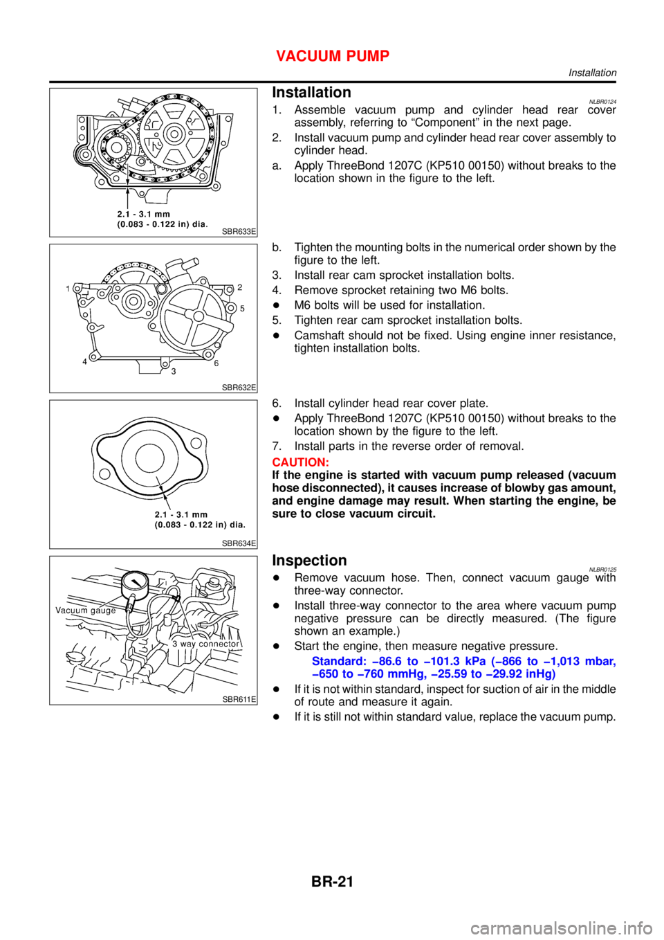
a. Apply ThreeBond 1207C (KP510 00150) without breaks to the
location shown in the figure to the left.
SBR632E
b. Tighten the mounting bolts in the numerical order shown by the
figure to the left.
3. Install rear cam sprocket installation bolts.
4. Remove sprocket retaining two M6 bolts.
+M6 bolts will be used for installation.
5. Tighten rear cam sprocket installation bolts.
+Camshaft should not be fixed. Using engine inner resistance,
tighten installation bolts.
SBR634E
6. Install cylinder head rear cover plate.
+Apply ThreeBond 1207C (KP510 00150) without breaks to the
location shown by the figure to the left.
7. Install parts in the reverse order of removal.
CAUTION:
If the engine is started with vacuum pump released (vacuum
hose disconnected), it causes increase of blowby gas amount,
and engine damage may result. When starting the engine, be
sure to close vacuum circuit.
SBR611E
InspectionNLBR0125+Remove vacuum hose. Then, connect vacuum gauge with
three-way connector.
+Install three-way connector to the area where vacuum pump
negative pressure can be directly measured. (The figure
shown an example.)
+Start the engine, then measure negative pressure.
Standard: �86.6 to �101.3 kPa (�866 to �1,013 mbar,
�650 to �760 mmHg, �25.59 to �29.92 inHg)
+If it is not within standard, inspect for suction of air in the middle
of route and measure it again.
+If it is still not within standard value, replace the vacuum pump.
VACUUM PUMP
Installation
BR-21
Page 259 of 3051
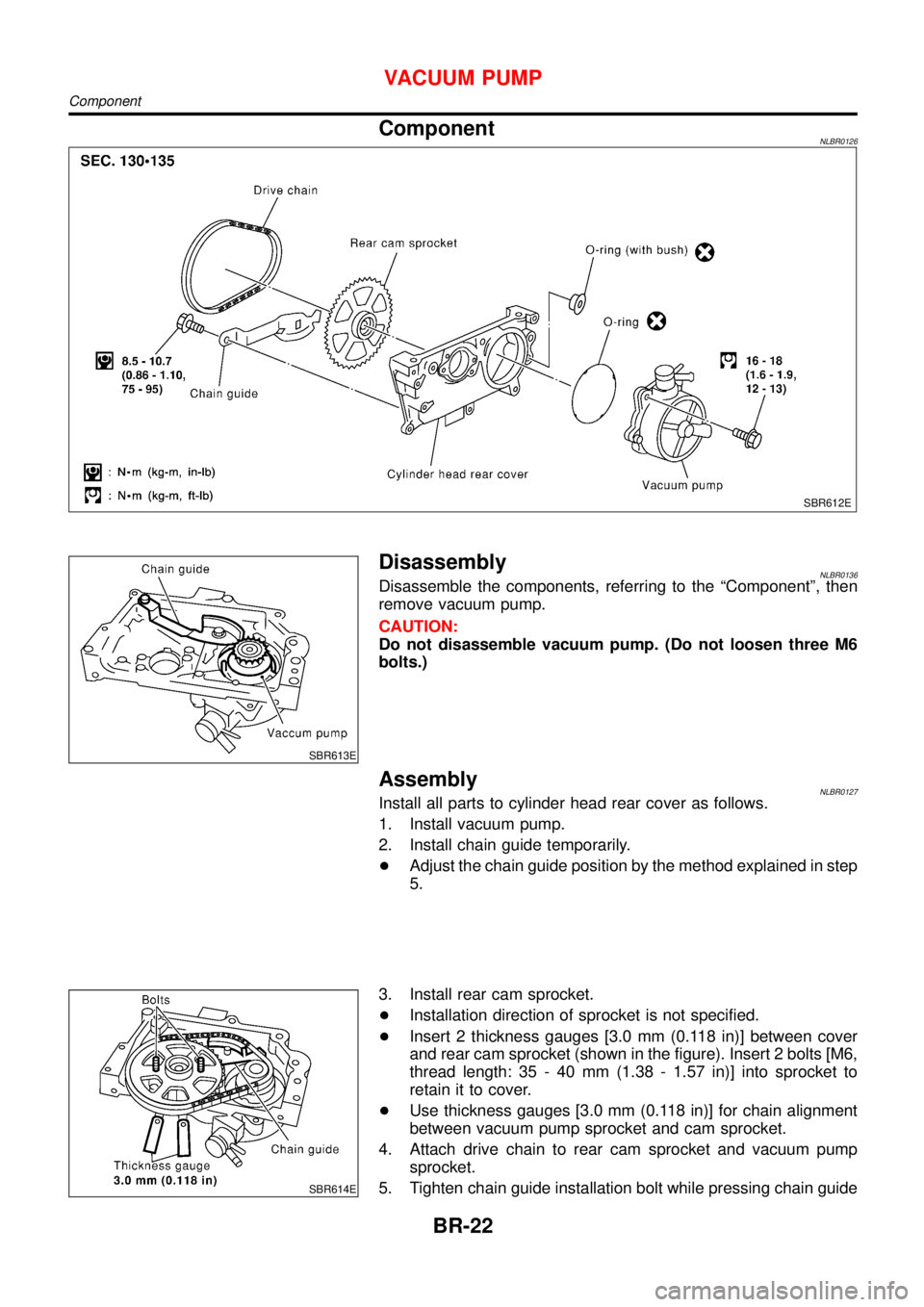
ComponentNLBR0126
SBR612E
SBR613E
DisassemblyNLBR0136Disassemble the components, referring to the“Component”, then
remove vacuum pump.
CAUTION:
Do not disassemble vacuum pump. (Do not loosen three M6
bolts.)
AssemblyNLBR0127Install all parts to cylinder head rear cover as follows.
1. Install vacuum pump.
2. Install chain guide temporarily.
+Adjust the chain guide position by the method explained in step
5.
SBR614E
3. Install rear cam sprocket.
+Installation direction of sprocket is not specified.
+Insert 2 thickness gauges [3.0 mm (0.118 in)] between cover
and rear cam sprocket (shown in the figure). Insert 2 bolts [M6,
thread length: 35 - 40 mm (1.38 - 1.57 in)] into sprocket to
retain it to cover.
+Use thickness gauges [3.0 mm (0.118 in)] for chain alignment
between vacuum pump sprocket and cam sprocket.
4. Attach drive chain to rear cam sprocket and vacuum pump
sprocket.
5. Tighten chain guide installation bolt while pressing chain guide
VACUUM PUMP
Component
BR-22
Page 260 of 3051
![NISSAN ALMERA TINO 2001 Service Repair Manual lightly [approximately 9.8 N (1.0 kg, 2.2 lb)].
6. Remove thickness gauges (2).
+Leave sprocket retaining bolts (M6) until installation.
VACUUM PUMP
Assembly (Cont’d)
BR-23 NISSAN ALMERA TINO 2001 Service Repair Manual lightly [approximately 9.8 N (1.0 kg, 2.2 lb)].
6. Remove thickness gauges (2).
+Leave sprocket retaining bolts (M6) until installation.
VACUUM PUMP
Assembly (Cont’d)
BR-23](/img/5/57352/w960_57352-259.png)
lightly [approximately 9.8 N (1.0 kg, 2.2 lb)].
6. Remove thickness gauges (2).
+Leave sprocket retaining bolts (M6) until installation.
VACUUM PUMP
Assembly (Cont’d)
BR-23