NISSAN ALMERA TINO 2001 Service Repair Manual
Manufacturer: NISSAN, Model Year: 2001, Model line: ALMERA TINO, Model: NISSAN ALMERA TINO 2001Pages: 3051, PDF Size: 46.38 MB
Page 401 of 3051
BODY (ALIGNMENT)
Alignment (Cont'd)
BT-70
Page 402 of 3051
CLUTCH
SECTION
CL
CONTENTS
PRECAUTIONS...............................................................2
Precautions ..................................................................2
PREPARATION...............................................................3
Special Service Tools ..................................................3
Commercial Service Tools ...........................................3
NOISE, VIBRATION AND HARSHNESS (NVH)
TROUBLESHOOTING.....................................................4
NVH Troubleshooting Chart.........................................4
CLUTCH...................................................................4
CLUTCH SYSTEM...........................................................5
Components - RHD Model with QG Engine - .............5
Components - LHD Model with QG Engine -..............6
Components - RHD Model with YD Engine -..............7
Components - LHD Model with YD Engine - ..............8
Inspection and Adjustment ..........................................9
CLUTCH PEDAL INSPECTION...................................9
CLUTCH PEDAL ADJUSTMENT...............................10
AIR BLEEDING PROCEDURE..................................10
CLUTCH MASTER CYLINDER..................................... 11
Components............................................................... 11
Removal .....................................................................12
Installation ..................................................................12
Disassembly...............................................................12
Inspection...................................................................12
Assembly ...................................................................13
OPERATING CYLINDER...............................................14
Components...............................................................14
Removal .....................................................................14
Disassembly...............................................................14
Inspection...................................................................14
Assembly ...................................................................15
Installation ..................................................................15
PIPING...........................................................................16
Removal .....................................................................16Installation ..................................................................16
RS5F70A
CLUTCH RELEASE MECHANISM...............................17
Components...............................................................17
Removal .....................................................................17
Inspection...................................................................17
Installation ..................................................................17
RS5F50A
CLUTCH RELEASE MECHANISM...............................20
Components...............................................................20
Removal .....................................................................20
Inspection...................................................................20
Installation ..................................................................20
CLUTCH DISC, CLUTCH COVER AND
FLYWHEEL....................................................................22
Components...............................................................22
Inspection and Adjustment ........................................22
CLUTCH DISC.........................................................22
CLUTCH COVER.....................................................23
FLYWHEEL.............................................................23
Installation ..................................................................23
SERVICE DATA AND SPECIFICATIONS (SDS).........24
Clutch Control System ...............................................24
Clutch Master Cylinder ..............................................24
Clutch Operating Cylinder .........................................24
Clutch Disc.................................................................24
Clutch Cover ..............................................................24
Clutch Pedal ..............................................................24
Page 403 of 3051
SBR820BA
PrecautionsNLCL0001+Recommended fluid is brake fluid ªDOT 4º. Refer to
MA-20, ªFluid and Lubricantsº.
+Never reuse drained brake fluid.
+Be careful not to splash brake fluid on painted areas.
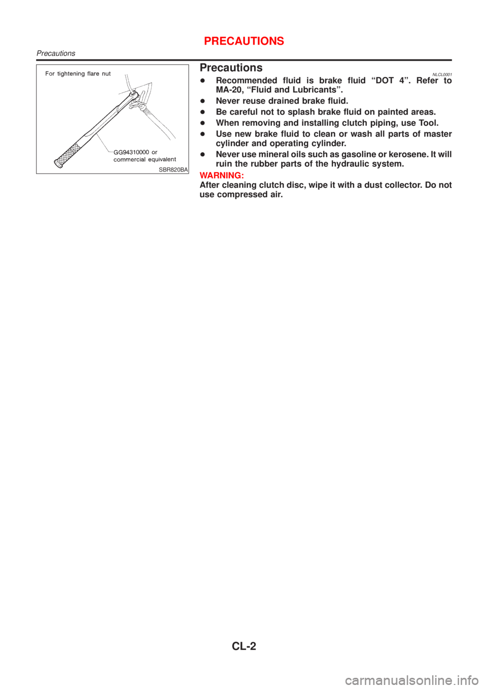
+When removing and installing clutch piping, use Tool.
+Use new brake fluid to clean or wash all parts of master
cylinder and operating cylinder.
+Never use mineral oils such as gasoline or kerosene. It will
ruin the rubber parts of the hydraulic system.
WARNING:
After cleaning clutch disc, wipe it with a dust collector. Do not
use compressed air.
PRECAUTIONS
Precautions
CL-2
Page 404 of 3051
Special Service ToolsNLCL0002
Tool number
Tool nameDescription
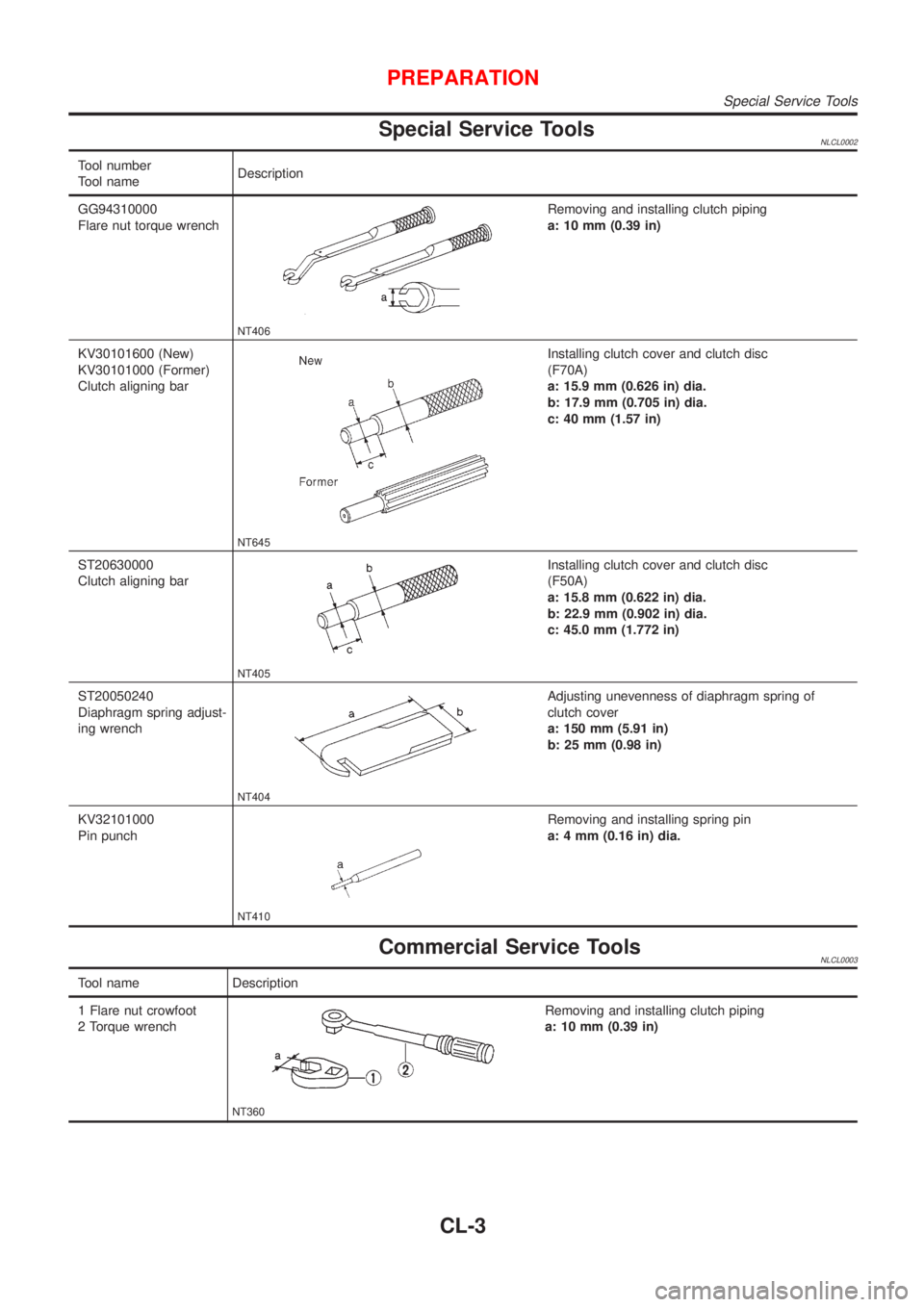
GG94310000
Flare nut torque wrench
NT406
Removing and installing clutch piping
a: 10 mm (0.39 in)
KV30101600 (New)
KV30101000 (Former)
Clutch aligning bar
NT645
Installing clutch cover and clutch disc
(F70A)
a: 15.9 mm (0.626 in) dia.
b: 17.9 mm (0.705 in) dia.
c: 40 mm (1.57 in)
ST20630000
Clutch aligning bar
NT405
Installing clutch cover and clutch disc
(F50A)
a: 15.8 mm (0.622 in) dia.
b: 22.9 mm (0.902 in) dia.
c: 45.0 mm (1.772 in)
ST20050240
Diaphragm spring adjust-
ing wrench
NT404
Adjusting unevenness of diaphragm spring of
clutch cover
a: 150 mm (5.91 in)
b: 25 mm (0.98 in)
KV32101000
Pin punch
NT410
Removing and installing spring pin
a: 4 mm (0.16 in) dia.
Commercial Service ToolsNLCL0003
Tool name Description
1 Flare nut crowfoot
2 Torque wrench
NT360
Removing and installing clutch piping
a: 10 mm (0.39 in)
PREPARATION
Special Service Tools
CL-3
Page 405 of 3051
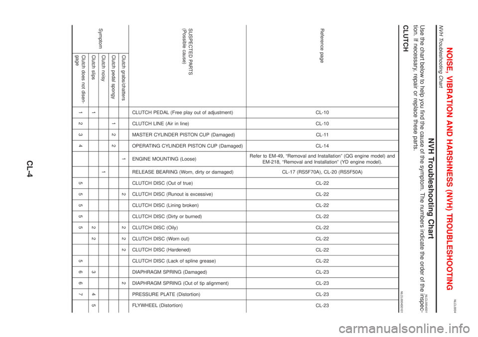
NLCL0004
NVH Troubleshooting ChartNLCL0004S01Use the chart below to help you find the cause of the symptom. The numbers indicate the order of the inspec-
tion. If necessary, repair or replace these parts.
CLUTCHNLCL0004S0101
Reference pageCL-10
CL-10
CL-11
CL-14
Refer to EM-49, ªRemoval and Installationº (QG engine model) and
EM-218, ªRemoval and Installationº (YD engine model).
CL-17 (RS5F70A), CL-20 (RS5F50A)
CL-22
CL-22
CL-22
CL-22
CL-22
CL-22
CL-22
CL-22
CL-23
CL-23
CL-23
CL-23
SUSPECTED PARTS
(Possible cause)
CLUTCH PEDAL (Free play out of adjustment)
CLUTCH LINE (Air in line)
MASTER CYLINDER PISTON CUP (Damaged)
OPERATING CYLINDER PISTON CUP (Damaged)
ENGINE MOUNTING (Loose)
RELEASE BEARING (Worn, dirty or damaged)
CLUTCH DISC (Out of true)
CLUTCH DISC (Runout is excessive)
CLUTCH DISC (Lining broken)
CLUTCH DISC (Dirty or burned)
CLUTCH DISC (Oily)
CLUTCH DISC (Worn out)
CLUTCH DISC (Hardened)
CLUTCH DISC (Lack of spline grease)
DIAPHRAGM SPRING (Damaged)
DIAPHRAGM SPRING (Out of tip alignment)
PRESSURE PLATE (Distortion)
FLYWHEEL (Distortion)
SymptomClutch grabs/chatters 1 2 2 2 2 2
Clutch pedal spongy 1 2 2
Clutch noisy 1
Clutch slips 1 2 2 3 4 5
Clutch does not disen-
gage1234 55555 5667
NOISE, VIBRATION AND HARSHNESS (NVH) TROUBLESHOOTING
NVH Troubleshooting Chart
CL-4
Page 406 of 3051
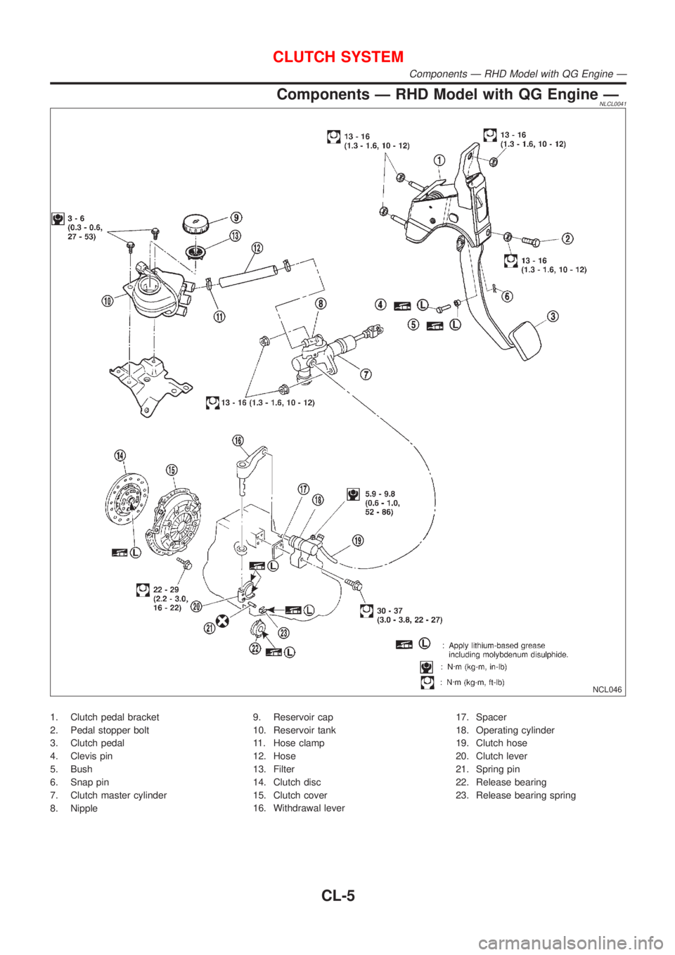
Components Ð RHD Model with QG Engine ÐNLCL0041
NCL046
1. Clutch pedal bracket
2. Pedal stopper bolt
3. Clutch pedal
4. Clevis pin
5. Bush
6. Snap pin
7. Clutch master cylinder
8. Nipple9. Reservoir cap
10. Reservoir tank
11. Hose clamp
12. Hose
13. Filter
14. Clutch disc
15. Clutch cover
16. Withdrawal lever17. Spacer
18. Operating cylinder
19. Clutch hose
20. Clutch lever
21. Spring pin
22. Release bearing
23. Release bearing spring
CLUTCH SYSTEM
Components Ð RHD Model with QG Engine Ð
CL-5
Page 407 of 3051
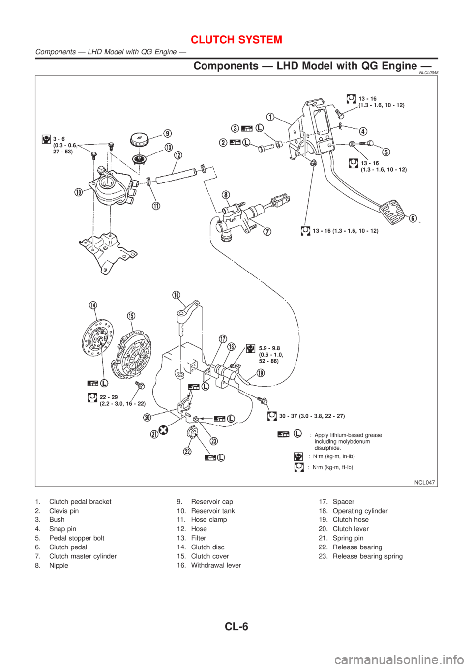
Components Ð LHD Model with QG Engine ÐNLCL0048
NCL047
1. Clutch pedal bracket
2. Clevis pin
3. Bush
4. Snap pin
5. Pedal stopper bolt
6. Clutch pedal
7. Clutch master cylinder
8. Nipple9. Reservoir cap
10. Reservoir tank
11. Hose clamp
12. Hose
13. Filter
14. Clutch disc
15. Clutch cover
16. Withdrawal lever17. Spacer
18. Operating cylinder
19. Clutch hose
20. Clutch lever
21. Spring pin
22. Release bearing
23. Release bearing spring
CLUTCH SYSTEM
Components Ð LHD Model with QG Engine Ð
CL-6
Page 408 of 3051
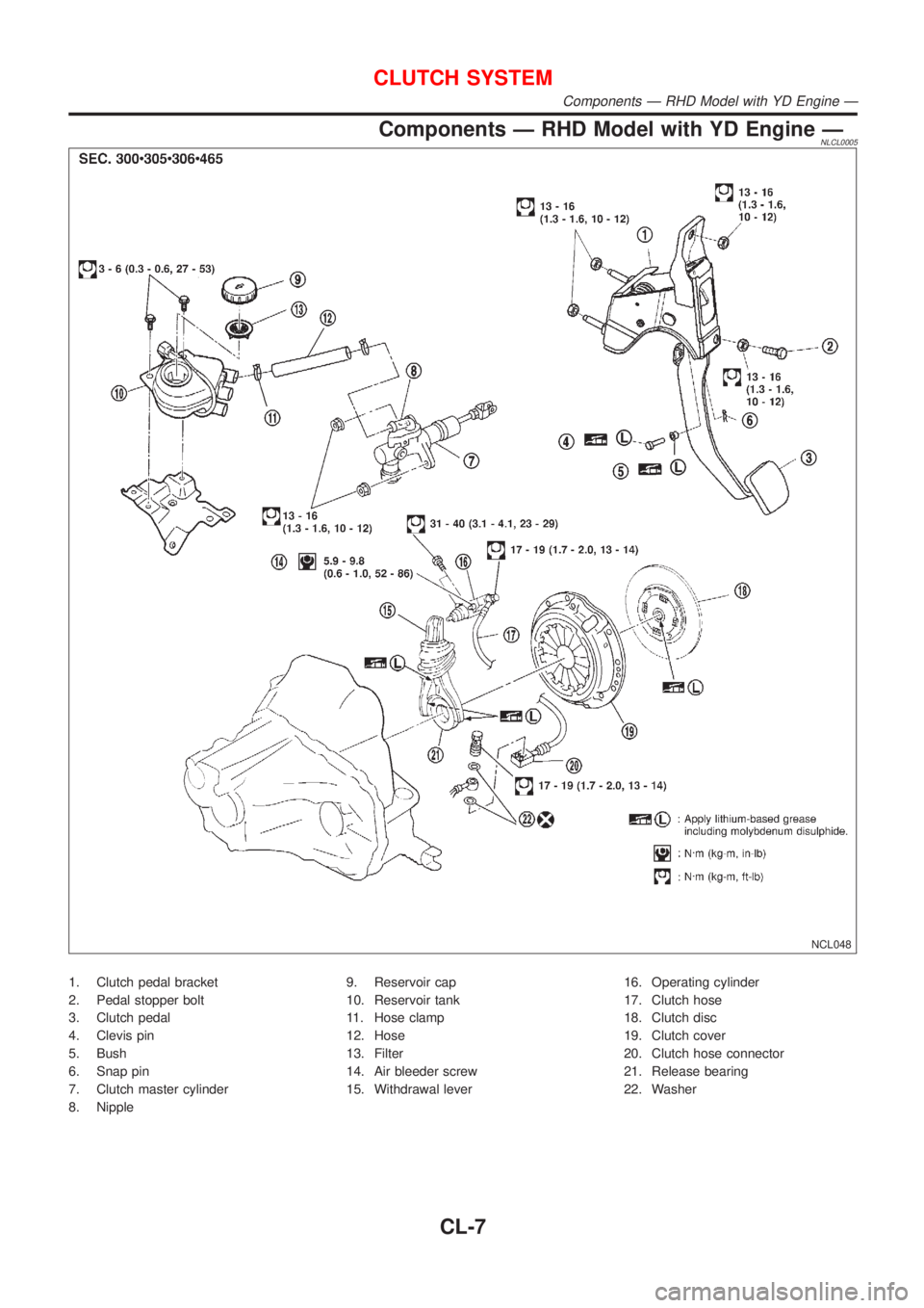
Components Ð RHD Model with YD Engine ÐNLCL0005
NCL048
1. Clutch pedal bracket
2. Pedal stopper bolt
3. Clutch pedal
4. Clevis pin
5. Bush
6. Snap pin
7. Clutch master cylinder
8. Nipple9. Reservoir cap
10. Reservoir tank
11. Hose clamp
12. Hose
13. Filter
14. Air bleeder screw
15. Withdrawal lever16. Operating cylinder
17. Clutch hose
18. Clutch disc
19. Clutch cover
20. Clutch hose connector
21. Release bearing
22. Washer
CLUTCH SYSTEM
Components Ð RHD Model with YD Engine Ð
CL-7
Page 409 of 3051
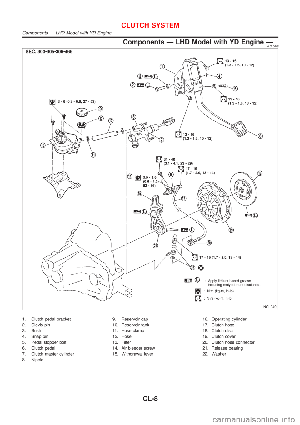
Components Ð LHD Model with YD Engine ÐNLCL0049
NCL049
1. Clutch pedal bracket
2. Clevis pin
3. Bush
4. Snap pin
5. Pedal stopper bolt
6. Clutch pedal
7. Clutch master cylinder
8. Nipple9. Reservoir cap
10. Reservoir tank
11. Hose clamp
12. Hose
13. Filter
14. Air bleeder screw
15. Withdrawal lever16. Operating cylinder
17. Clutch hose
18. Clutch disc
19. Clutch cover
20. Clutch hose connector
21. Release bearing
22. Washer
CLUTCH SYSTEM
Components Ð LHD Model with YD Engine Ð
CL-8
Page 410 of 3051
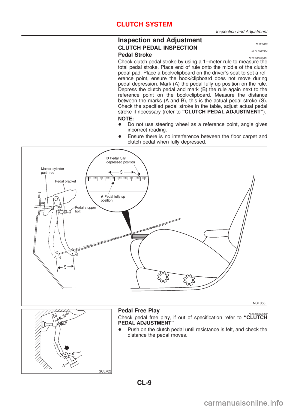
Inspection and AdjustmentNLCL0006CLUTCH PEDAL INSPECTIONNLCL0006S04Pedal StrokeNLCL0006S0401Check clutch pedal stroke by using a 1±meter rule to measure the
total pedal stroke. Place end of rule onto the middle of the clutch
pedal pad. Place a book/clipboard on the driver's seat to set a ref-
erence point, ensure the book/clipboard does not move during
pedal depression. Mark (A) the pedal fully up position on the rule.
Depress the clutch pedal and mark (B) the rule again next to the
reference point on the book/clipboard. Measure the distance
between the marks (A and B), this is the actual pedal stroke (S).
Check the specified pedal stroke in the table, adjust actual pedal
stroke if necessary (refer toªCLUTCH PEDAL ADJUSTMENTº).
NOTE:
+Do not use steering wheel as a reference point, angle gives
incorrect reading.
+Ensure there is no interference between the floor carpet and
clutch pedal when fully depressed.
NCL058
SCL702
Pedal Free PlayNLCL0006S0402Check pedal free play, if out of specification refer toªCLUTCH
PEDAL ADJUSTMENTº
+Push on the clutch pedal until resistance is felt, and check the
distance the pedal moves.
CLUTCH SYSTEM
Inspection and Adjustment
CL-9